Software and Systems Engineering Standards: Verification and Validation of Sy...
Bank network project report routing configurations
1. 1
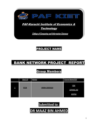
PROJECT NAME
BANK NETWORK PROJECT REPORT
Group Members
Stud. ID Names Course Name/CID
1 8718 ARIBA SIDDIQUI
I$IA
(SPRING 20)
103762
Submitted to :
DR MAAZ BIN AHMED
PAF-Karachi Institute of Economics &
Technology
College of Computing and Information Sciences
4. 4
63. Figure 34 Routing Table Consumer Branch...............................................................................39
64. Figure 35 Routing Table BZU Branch ........................................................................................40
65. Figure 36 Routing Table Executive Villas ..................................................................................41
66. Figure 37 Routing Table Nishter Medical..................................................................................42
67. Figure 38 Routing Table Lodhi Colony ......................................................................................43
68. Figure 39 Routing Table Border Router 1 .................................................................................44
69. Figure 40 Routing Table Border Router 4 .................................................................................45
70. Figure 41 Routing Table Border Router 3 .................................................................................46
71. Figure 42 Routing Table Border Router 2 .................................................................................47
72. Figure 43 Routing Table Jauhar Branch ....................................................................................48
73. PING Result of NATTING:..........................................................................................................49
74. Figure 44 Ping Result Natting ...................................................................................................49
75. Figure 45 Ping result natting.....................................................................................................49
76. Figure 46 Port-security .............................................................................................................50
77. ACL PING RESULTS:...................................................................................................................50
78. FTP Authorized:........................................................................................................................50
79. Figure 47 FTP Authorized .........................................................................................................50
80. FTP Unauthorized:....................................................................................................................51
81. Figure 48 FTP UNauthorized.....................................................................................................51
82. WEB SERVER AUTHORIZED:......................................................................................................51
83. .................................................................................................................................................51
84. Figure 49 Web Server Authorized.............................................................................................51
85. WEB SERVER UNAUTHORIZED:.................................................................................................52
86. Figure 50 Web Server Unauthorized.........................................................................................52
87. DNS SERVER AUTHORIZED........................................................................................................52
88. Figure 51 DNS Server Authorized .............................................................................................52
89. DNS SERVER UNAUTHORIZED...................................................................................................53
90. Figure 52 DNS server Unauthorized..........................................................................................53
5. 5
NETWORK DIAGRAM:
The Network of 15 Routers is divided into 4 Clusters. 4 Clusters indicate 4
Cities. KARACHI is the head of all cities So, OSPF Routing Protocol also ACL
is implemented on this cluster. All the Routers have public IPs and all the
PCs have private IPs Class A (10.1.1.0/24 , 10.1.2.0/24) , Class B
(172.16.1.0/24 , 172.16.2.0/24) , Class C ( 192.168.1.0/24 , 192.168.2.0/24).
Static Routing Technique & NATTING is implemented on Islamabad. RIPV2 &
Port-Security is implemented on Lahore. EIGRP and Port-Security is
implemented on Multan Cluster. Route Redistribution is implemented on all
border Router. Also the Routing Protocol from which the Border Router is
connected is also configured.
Figure 1 Topology DIAGRAM
6. 6
Open Shortest Path First (OSPF)
Introduction:
Open Shortest Path First (OSPF) is a dynamic routing protocol for use
in Internet Protocol (IP) networks. Specifically, it is a link-state routing
protocol and falls into the group of interior gateway protocols, operating
within a single autonomous system (AS).
OSPF is used to determine the best route for delivering the packets within an
IP networks.
Enabling the OSPF Routing Protocol:
The following command is needed in order to enable OSPF routing protocol
on the router:
Router(config)#router ospf process-number
The process-number is nothing more than a number local to the router. It’s
only used to distinguish processes within a router and can be given an
arbitrary value. This value does not have to be the same on every router
within the area. However, it is always good practice to keep this number the
same for better administration.
Defining OSPF Networks:
Enabling OSPF is not enough to activate it. The OSPF process needs to know
the networks that are going to be advertised (i.e. the interfaces on which
OSPF will run) and the area they reside in. Therefore the following command
is needed to make OSPF operational:
Router(config-router)#network address wildcard-mask area area-number
The address can be the network address, subnet, or the address of a specific
interface.
7. 7
The network command is used to identify the interfaces on the router that
are going to participate in the OSPF process. Adjacencies will be created
with these interfaces and LSAs will be received and transmitted on these
interfaces.
Therefore the wildcard-mask parameter needs to be defined for accurately
identifying the necessary interfaces.
The wildcard-mask consists of 4 groups of 8-bits each. Each 0 bit indicates a
“must” and each 1 bit indicates an “any”. This will become clearer in the
next section on Defining OSPF Networks Examples.
The area-number specifies the area to be associated with the specific
address and consequently the interfaces to be grouped within that area.
By default, area 0 is used; if more than one area is to be created in a
network, area 0 is the first one that needs to be defined.
Advantages of OSPF :
OSPF is an open standard, not related to any particular vendor.
OSPF is hierarchical routing protocol, using area 0 (Autonomous System) at
the top of the hierarchy.
OSPF uses Link State Algorithm, and an OSPF network diameter can be much
larger than that of RIP.
OSPF supports Variable Length Subnet Masks (VLSM), resulting in efficient
use of networking resources.
OSPF uses multicasting within areas.
After initialization, OSPF only sends updates on routing table sections which
have changed, it does not send the entire routing table, which in turn
conserves network bandwidth.
Using areas, OSPF networks can be logically segmented to improve
administration, and decrease the size of routing tables.
Disadvantages of OSPF:
OSPF is very processor intensive due to implementation of SPF algorithm.
OSPF maintains multiple copies of routing information, increasing the
amount of memory needed.
OSPF is a more complex protocol to implement compared to RIP.
8. 8
ACL :
ACL provide security on basis of IP address. There are two types of ACL.
Standard ACL (1-99)
Extended ACL (100-199)
We have implemented Extended ACL on Korangi Branch. The Authorized PC
have the access of all the servers. While, the unauthorized PC can’t access
the Server’s services. ACL will not block the data packets but it will block
the services of web , ftp , email & DNS for the unauthorized PCs.
Command:
Access-list [access-list ID] permittcp host [PC IP] host [Server IP] eq
[Server]
Access-list [access-list ID] deny tcp any host [Server IP] eq [Server]
Access-list [access-list ID] permitip any any
NETWORK DIAGRAM OF OSPF:
Figure 2 Karachi OSPF
9. 9
STATIC ROUTING TECHNIQUE:
Simple Static Routing Technique is implemented on this Cluster.
Command :
Ip route network mask next hop
Also DYNAMIC NATTINGis implemented on this Cluster. The advantage of
dynamic natting is we make pool of public IPs to translate it into private. If
any of the IP is down in dynamic the other IPs of pool is available for
translation. This advantage of Dynamic Natting is a Disadvantage of Static
Natting.
COMMAND FOR DYNAMIC NATTING :
Ip NAT pool [poolname] public-IPs-netmask mask-of-public IPs
Access-list [AccessListID] permit Private-IPs Inverse-Mask
Ip NAT inside source list [SourceListID] pool [Poolname]
Interface [Public]
Ip nat outside
Interca [Private]
IP nat inside
10. 10
NETWORK DIAGRAM OF STATIC:
Figure 3 Static Islamabad
Rip V2 :
Introduction
Classless Routing Protocols
The true characteristic of a classless routing protocol is the ability to
carry subnet masks in their route advertisements.
Classless Routing Protocol, sent over UDP port 520
• Includes the subnet mask in the routing updates.
• Automatic summarization at major network boundaries can be disabled.
11. 11
• Updates sent as multicasts unless the neighbor command is uses which
Sends them as unicasts.
Configuring static Routes
RipV2
Discontiguous subnets and classless routing
12. 12
RIP v1 always uses automatic summarization.
The default behavior of RIP v2 is to summarize at network boundaries
the same as RIP v1.
PORT SECURITY
Port-Security provide security on basis of MAC-address. We implement
Port-Security on Switch.
NETWORK DIAGRAM OF RIPV2:
Figure 4 RIPV2 Lahore
13. 13
SHOW IP INTERFACE BRIEF COMMAND :
Figure 5Korangi Branch
Figure 6Jauhar Branch