
Recommended
More Related Content
What's hot
What's hot (20)
Similar to Waveguides.ppt
Similar to Waveguides.ppt (20)
Recently uploaded
Recently uploaded (20)
Waveguides.ppt
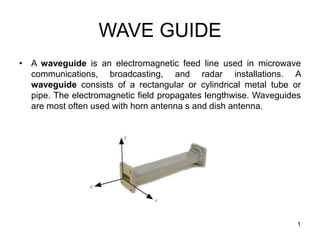
- 1. WAVE GUIDE • A waveguide is an electromagnetic feed line used in microwave communications, broadcasting, and radar installations. A waveguide consists of a rectangular or cylindrical metal tube or pipe. The electromagnetic field propagates lengthwise. Waveguides are most often used with horn antenna s and dish antenna. 1
- 2. Introduction At frequencies higher than 3 GHz, transmission of electromagnetic energy along the transmission lines and cables becomes difficult. This is due to the losses that occur both in the solid dielectric needed to support the conductor and in the conductors themselves. A metallic tube can be used to transmit electromagnetic wave at the above frequencies 2
- 3. Waveguides • Rectangular Waveguides – TEM, TE and TM waves – Cutoff Frequency – Wave Propagation – Wave Velocity, 3
- 4. 4 Possible Types of modes 1. Transverse Electro Magnetic (TEM) wave: Here both electric and magnetic fields are directed components. (i.e.) E z = 0 and Hz = 0 2. Transverse Electric (TE) wave: Here only the electric field is purely transverse to the direction of propagation and the magnetic field is not purely transverse. (i.e.) E z = 0, Hz ≠ 0
- 5. 5 4. Hybrid (HE) wave: Here neither electric nor magnetic fields are purely transverse to the direction of propagation. (i.e.) E z ≠ 0, Hz ≠ 0. 3. Transverse Magnetic (TM) wave: Here only magnetic field is transverse to the direction of propagation and the electric field is not purely transverse. (i.e.) E z ≠ 0, Hz = 0. Possible Types of modes
- 6. 6
- 7. 7 Rectangular Waveguides Any shape of cross section of a waveguide can support electromagnetic waves of which rectangular and circular waveguides have become more common. A waveguide having rectangular cross section is known as Rectangular waveguide
- 8. 8 Rectangular waveguide Dimensions of the waveguide which determines the operating frequency range
- 9. 9 1. The size of the waveguide determines its operating frequency range. 2. The frequency of operation is determined by the dimension ‘a’. 3. This dimension is usually made equal to one – half the wavelength at the lowest frequency of operation, this frequency is known as the waveguide cutoff frequency. 4. At the cutoff frequency and below, the waveguide will not transmit energy. At frequencies above the cutoff frequency, the waveguide will propagate energy. Dimensions of the waveguide which determines the operating frequency range:
- 10. 10 Wave paths in a waveguide at various frequencies Angle of incidence(A) Angle of reflection (B) (A = B) (a)At high frequency (b) At medium frequency ( c ) At low frequency (d) At cutoff frequency
- 11. 11 Wave propagation When a probe launches energy into the waveguide, the electromagnetic fields bounce off the side walls of the waveguide as shown in the above diagram. The angles of incidence and reflection depend upon the operating frequency. At high frequencies, the angles are large and therefore, the path between the opposite walls is relatively long as shown in Fig.
- 12. 12 At lower frequency, the angles decrease and the path between the sides shortens. When the operating frequency is reaches the cutoff frequency of the waveguide, the signal simply bounces back and forth directly between the side walls of the waveguide and has no forward motion. At cut off frequency and below, no energy will propagate.
- 13. 13 Cut off frequency The exact size of the wave guide is selected based on the desired operating frequency. The size of the waveguide is chosen so that its rectangular width is greater than one – half the wavelength but less than the one wavelength at the operating frequency. This gives a cutoff frequency that is below the operating frequency, thereby ensuring that the signal will be propagated down the line.
- 14. 14 Representation of modes The general symbol of representation will be TE m, n or TM m, n where the subscript m indicates the number of half wave variations of the electric field intensity along the b ( wide) dimension of the waveguide. The second subscript n indicates the number of half wave variations of the electric field in the a (narrow) dimension of the guide. The TE 1, 0 mode has the longest operating wavelength and is designated as the dominant mode. It is the mode for the lowest frequency that can be propagated in a waveguide.
- 15. 15 Expression for cut off wavelength For a standard rectangular waveguide, the cutoff wavelength is given by, 2 2 2 b n a m c Where a and b are measured in centimeters
- 16. 16 A Hollow metallic tube of uniform circular cross section for transmitting electromagnetic waves by successive reflections from the inner walls of the tube is called Circular waveguide. Circular wave guide
- 17. 17 Circular wave guide The circular waveguide is used in many special applications in microwave techniques. It has the advantage of greater power – handling capacity and lower attenuation for a given cutoff wavelength. However, the disadvantage of somewhat greater size and weight. The polarization of the transmitted wave can be altered due to the minor irregularities of the wall surface of the circular guide, whereas the rectangular wave guide the polarization is fixed
- 18. 18
- 19. 19 Description The wave of lowest frequency or the dominant mode in the circular waveguide is the TE11 mode. The first subscript m indicates the number of full – wave variations of the radial component of the electric field around the circumference of the waveguide. The second subscript n indicates the number of half – wave variations across the diameter. The field configurations of TE11 mode in the circular waveguide is shown in the diagram below
- 20. 20 Cut off wavelength The cutoff wavelength for dominant mode of propagation TE11 in circular waveguide of radius ‘a’ is given by 1.814 π 2 a c The cutoff wavelength for dominant mode of propagation TM01 in circular waveguide of radius ‘a’ is given by 2.405 π 2 a c
- 21. 21 Applications of circular waveguide Rotating joints in radars to connect the horn antenna feeding a parabolic reflector (which must rotate for tracking) TE01 mode suitable for long distance waveguide transmission above 10 GHz. Short and medium distance broad band communication (could replace / share coaxial and microwave links)
- 22. 22 Worked Example 2.4 The dimensions of the waveguide are 2.5 cm 1 cm. The frequency is 8.6 GHz. Find (i) possible modes and (ii) cut – off frequency for TE waves. Solution: Given a = 2.5 cm , b = 1 cm and f = 8.6 GHz Free space wavelength cm 488 . 3 10 8 10 3 9 10 0 f C
- 23. 23 Solution The condition for the wave to propagate is that λC > λ0 For TE01 mode cm 2 1 2 2 2 2 2 2 2 2 2 b a ab a n b m ab C Since λC < λ0, TE01 does not propagate
- 24. 24 For TE10 mode, λC = 2a = 2 2.5 = 5 cm Since λC > λ0 , TE10 mode is a possible mode. Cut – off frequency = GHz 6 5 10 3 10 C C C f Cut-off wavelength for TE11 mode cm 856 . 1 ) 1 ( ) 5 . 2 ( 1 5 . 2 2 2 2 2 2 2 b a ab For TE11 λC < λ0 , TE11 is not possible. The possible mode is TE10 mode. The cut – off frequency = 6 GHz =
- 25. 25 Worked Example 2.5 For the dominant mode propagated in an air filled circular waveguide, the cut – off wavelength is 10 cm. Find (i) the required size or cross sectional area of the guide and (ii) the frequencies that can be used for this mode of propagation The cut – off wavelength = λC = 10 cm The radius of the circular waveguide , cm 3 9 . 2 2 841 . 1 10 = r
- 26. Waveguides • In the previous chapters, a pair of conductors was used to guide electromagnetic wave propagation. This propagation was via the transverse electromagnetic (TEM) mode, meaning both the electric and magnetic field components were transverse, or perpendicular, to the direction of propagation. • In this chapter we investigate wave- guiding structures that support propagation in non-TEM modes, namely in the transverse electric (TE) and transverse magnetic (TM) modes. • In general, the term waveguide refers to constructs that only support non- TEM mode propagation. Such constructs share an important trait: they are unable to support wave propagation below a certain frequency, termed the cutoff frequency. Rectangular waveguide Circular waveguide Optical Fiber Dielectric Waveguide 26
- 27. Rectangular Waveguide Location of modes • Let us consider a rectangular waveguide with interior dimensions are a x b, • Waveguide can support TE and TM modes. – In TE modes, the electric field is transverse to the direction of propagation. – In TM modes, the magnetic field that is transverse and an electric field component is in the propagation direction. • The order of the mode refers to the field configuration in the guide, and is given by m and n integer subscripts, TEmn and TMmn. – The m subscript corresponds to the number of half-wave variations of the field in the x direction, and – The n subscript is the number of half-wave variations in the y direction. • A particular mode is only supported above its cutoff frequency. The cutoff frequency is given by 2 2 2 2 1 2 2 mn r r c m n c m n f a b a b Rectangular Waveguide 1 1 1 1 o r o r o o r r r r c u 8 where 3 10 m/s c 27
- 28. Table 7.1: Some Standard Rectangular Waveguide Waveguide Designation a (in) b (in) t (in) fc10 (GHz) freq range (GHz) WR975 9.750 4.875 .125 .605 .75 – 1.12 WR650 6.500 3.250 .080 .908 1.12 – 1.70 WR430 4.300 2.150 .080 1.375 1.70 – 2.60 WR284 2.84 1.34 .080 2.08 2.60 – 3.95 WR187 1.872 .872 .064 3.16 3.95 – 5.85 WR137 1.372 .622 .064 4.29 5.85 – 8.20 WR90 .900 .450 .050 6.56 8.2 – 12.4 WR62 .622 .311 .040 9.49 12.4 - 18 Location of modes Rectangular Waveguide Rectangular Waveguide The cutoff frequency is given by 2 2 2 mn r r c c m n f a b 2 2 2 mn c c m n f a b 8 where 3 10 m/s c r r For air 1 and 1 28
- 29. To understand the concept of cutoff frequency, you can use the analogy of a road system with lanes having different speed limits. 29
- 30. Rectangular Waveguide Rectangular Waveguide • Let us take a look at the field pattern for two modes, TE10 and TE20 – In both cases, E only varies in the x direction; since n = 0, it is constant in the y direction. – For TE10, the electric field has a half sine wave pattern, while for TE20 a full sine wave pattern is observed. 30
- 31. Rectangular Waveguide Example Let us calculate the cutoff frequency for the first four modes of WR284 waveguide. From Table 7.1 the guide dimensions are a = 2.840 mils and b = 1.340 mils. Converting to metric units we have a = 7.214 cm and b = 3.404 cm. 2 2 2 mn c c m n f a b 8 10 3 10 100 2.08 GHz 2 2 7.214 1 c m x c cm s f a cm m 8 01 3 10 100 4.41 GHz 2 2 3.404 1 c m x c cm s f b cm m 20 4.16 GHz c c f a 8 2 2 11 3 10 1 1 100 4.87 GHz 2 7.214 3.404 1 c m x cm s f cm cm m TE10: TE01: 8 where 3 10 m/s c TE20: TE11: TE10 TE01 TE20 TE11 2.08 GHz 4.16 GHz 4.41 GHz 4.87 GHz TM11 31
- 32. Rectangular Waveguide Example 8 For air 3 10 m/s c 32
- 33. Rectangular Waveguide - Wave Propagation We can achieve a qualitative understanding of wave propagation in waveguide by considering the wave to be a superposition of a pair of TEM waves. Let us consider a TEM wave propagating in the z direction. Figure shows the wave fronts; bold lines indicating constant phase at the maximum value of the field (+Eo), and lighter lines indicating constant phase at the minimum value (-Eo). The waves propagate at a velocity uu, where the u subscript indicates media unbounded by guide walls. In air, uu = c. 33
- 34. Now consider a pair of identical TEM waves, labeled as u+ and u- in Figure (a). The u+ wave is propagating at an angle + to the z axis, while the u- wave propagates at an angle –. These waves are combined in Figure (b). Notice that horizontal lines can be drawn on the superposed waves that correspond to zero field. Along these lines the u+ wave is always 180 out of phase with the u- wave. Rectangular Waveguide - Wave Propagation 34
- 35. Rectangular Waveguide - Wave Propagation Since we know E = 0 on a perfect conductor, we can replace the horizontal lines of zero field with perfect conducting walls. Now, u+ and u- are reflected off the walls as they propagate along the guide. The distance separating adjacent zero-field lines in Figure (b), or separating the conducting walls in Figure (a), is given as the dimension a in Figure (b). The distance a is determined by the angle and by the distance between wavefront peaks, or the wavelength . For a given wave velocity uu, the frequency is f = uu/. If we fix the wall separation at a, and change the frequency, we must then also change the angle if we are to maintain a propagating wave. Figure (b) shows wave fronts for the u+ wave. The edge of a +Eo wave front (point A) will line up with the edge of a –Eo front (point B), and the two fronts must be /2 apart for the m = 1 mode. (a) (b) a 35
- 36. Rectangular Waveguide - Wave Propagation The waveguide can support propagation as long as the wavelength is smaller than a critical value, c, that occurs at = 90, or 2 u c c u a m f Where fc is the cutoff frequency for the propagating mode. sin c c f f We can relate the angle to the operating frequency and the cutoff frequency by 2 sin m a For any value of m, we can write by simple trigonometry 2 sin u u a m f 36
- 37. Rectangular Waveguide - Wave Propagation A constant phase point moves along the wall from A to D. Calling this phase velocity up, and given the distance lAD is 2 cos AD m l Then the time tAD to travel from A to D is 2 cos AD p p AD l m t u u Since the times tAD and tAC must be equal, we have cos u p u u The time tAC it takes for the wavefront to move from A to C (a distance lAC) is 2 Wavefront Velocity Distance from A to C AC u u AC l m t u u 37
- 38. 2 1 u p c u u f f Rectangular Waveguide - Wave Propagation 2 2 2 cos cos 1 sin 1 c f f cos u p u u The Phase velocity is given by using cos G u u u 2 1 c G u f u u f The Group velocity is given by The Wave velocity is given by 1 1 1 1 u o r o r o o r r r r c u 8 where 3 10 m/s c Wave velocity Phase velocity p u Group velocity Beach Ocean Phase velocity p u u u Wave velocity u u G u Group velocity Analogy! Point of contact 38
- 39. Rectangular Waveguide - Wave Propagation The ratio of the transverse electric field to the transverse magnetic field for a propagating mode at a particular frequency is the waveguide impedance. 2 , 1 TE u mn c Z f f For a TE mode, the wave impedance is For a TM mode, the wave impedance is 2 . 1 TM c mn u f Z f 2 1 c u f f The phase constant is given by 2 1 u c f f The guide wavelength is given by 39
- 41. Example Rectangular Waveguide Let’s determine the TE mode impedance looking into a 20 cm long section of shorted WR90 waveguide operating at 10 GHz. From the Waveguide Table 7.1, a = 0.9 inch (or) 2.286 cm and b = 0.450 inch (or) 1.143 cm. 2 2 2 mn c c m n f a b TE10 6.56 GHz Mode Cutoff Frequency TE01 13.12 GHz TE11 14.67 GHz TE20 13.13 GHz TE02 26.25 GHz At 10 GHz, only the TE10 mode is supported! TE10 6.56 GHz Mode Cutoff Frequency TE01 13.12 GHz TE11 14.67 GHz TE20 13.13 GHz TE02 26.25 GHz TE10 TE20 TE01 TE11 TM11 6.56 GHz 13.12 GHz TE02 26.25 GHz 14.67 GHz Rearrange 13.13 GHz 41
- 42. Example Rectangular Waveguide 10 2 120 500 . 6.56GHz 1- 10GHz TE Z 10 tan IN TE Z jZ l The impedance looking into a short circuit is given by The TE10 mode impedance 2 2 9 2 8 2 1 1 2 10 10 6.56 1 158 10 3 10 c c u f f f f c f x Hz GHz rad m GHz m x s The TE10 mode propagation constant is given by 500 tan 31.6 100 IN Z j j 500 tan 158 0.2 IN rad Z j m m 42