

Recommended
Recommended
More Related Content
What's hot
What's hot (20)
Similar to SilverDust D2 IG datasheet summary
Similar to SilverDust D2 IG datasheet summary (20)
More from Electromate
More from Electromate (20)
Recently uploaded
Recently uploaded (20)
SilverDust D2 IG datasheet summary
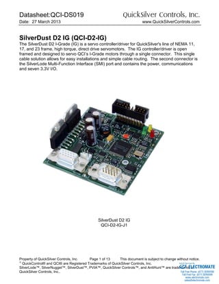
- 1. Datasheet:QCI-DS019 QuickSilver Controls, Inc. Date: 27 March 2013 www.QuickSilverControls.com Property of QuickSilver Controls, Inc. Page 1 of 13 This document is subject to change without notice. QuickControl® and QCI® are Registered Trademarks of QuickSilver Controls, Inc. SilverLode™, SilverNugget™, SilverDust™, PVIA™, QuickSilver Controls™, and AntiHunt™ are trademarks of QuickSilver Controls, Inc.. SilverDust D2 IG (QCI-D2-IG) The SilverDust D2 I-Grade (IG) is a servo controller/driver for QuickSilver's line of NEMA 11, 17, and 23 frame, high torque, direct drive servomotors. The IG controller/driver is open framed and designed to servo QCI’s I-Grade motors through a single connector. This single cable solution allows for easy installations and simple cable routing. The second connector is the SilverLode Multi-Function Interface (SMI) port and contains the power, communications and seven 3.3V I/O. SilverDust D2 IG QCI-D2-IG-J1 ELECTROMATE Toll Free Phone (877) SERVO98 Toll Free Fax (877) SERV099 www.electromate.com sales@electromate.com Sold & Serviced By:
- 2. Datasheet:QCI-DS019 QuickSilver Controls, Inc. QuickSilver Controls, Inc. Page 2 of 13 System Overview Point-to-Point Moves • Relative or Absolute • Velocity or Time Based • S-Curve Advanced Motion Profile Moves • Profile Move Commands • Register Based o Position/Accel/Decel/Vel o Modify On-the-Fly Multi-Axis Linear Interpolation • XYZ Coords Contained in Text File • CANopen® used for local bus • 1000+ Points Stored In NV Memory Built-In Voltage Clamp • Regenerative Braking Resistor Input/Output • 7 TTL Digital I/O o Use for QCI-BO-B52 24V I/O • 4 Analog Inputs (Joystick) • Analog Output Option • Programmable Limit Switch (PLS) o Dynamically Sets Output Dependent on Motor Position • Secondary Encoder In • Encoder Out Program and Data Storage • 32K Non-Volatile Memory: • 2000-3000 Program Lines • User Data Examples o CAM Tables o Motion Profiles o Lookup Tables Electronic Slip Clutch/Brake • Variable Torque • Wind/Unwind Applications Anti-Hunt™ • Optionally use Open Loop While Holding • No Servo Dither While At Rest Electronic Gearing/Camming • Follow Encoder (A/B Quadrature) or Step and Direction • Dynamic Gear Ratios o Integer Ratios 32767:1 to 1:32767 o Decimal Ratios to 7 Places • Electronic Cam o Import Tables From Text File o Over 2500 Points o Multiple Tables Communications • RS-485/RS-232 @ 230K Baud • ASCII,Binary,Modbus®,DMX512 • Host Control While Servo in Motion • CANopen® (optional) Programming Language • Easy, Menu Driven Interface • Command Parameter Prompts • No Syntax Errors • User Namable I/O and Registers Advance PVIA™ Servo Loop • 100:1 Inertial Mismatch • Direct Drive Oversized Inertial Loads o Flywheels/Belt Drives o Typically Without Gearheads • More Stable Than PID Digital 4 Quadrant Vector Drive • DSP Driven for Reduced Noise Multi-Task/Multi-Thread Compatible with QCI Motor/Encoders • NEMA 11 Frame o 4000 Counts/Rev Encoder o Up To 9 oz-in (continuous) • NEMA 17 Frame o 8000 Counts/Rev Encoder o Up To 43 oz-in (continuous) o IP50 or IP65 • NEMA 23 Frame o 8000 Counts/Rev Encoder o Up To 300 oz-in (continuous) o IP50 or IP65 UL, CUL, CE ELECTROMATE Toll Free Phone (877) SERVO98 Toll Free Fax (877) SERV099 www.electromate.com sales@electromate.com Sold & Serviced By:
- 3. Datasheet:QCI-DS019 QuickSilver Controls, Inc. QuickSilver Controls, Inc. Page 3 of 13 Electrical Specifications Input Power Voltage +12 VDC to +48 VDC, regulated. Device must be initialized for the actual operating voltage. Over-Voltage Protection None available. Voltages exceeding +55 VDC will permanently damage the controller/driver electronics. The IG includes an onboard clamp circuit. The bare-board configuration includes the clamp circuit, but must have an external resistor connected prior to connecting any motor. A suitable value is V+/5 (ohms), but not more than 10 ohms, nor less than V+/6 ohms. Power rating is dependent upon operation, but should be at least 10W. Reverse Polarity Protection Reverse polarity protection is available on the SilverDust IG. (Note, however, if power supply is not floating, connecting the V+ input to Ground will cause this potential to be present at the communications and I/O lines, which may damage these lines or that to which they are connected. Input Current 4 Amps maximum for any input voltage, +12 VDC to +48 VDC. Output Power Output/Driver Current 3.5 Amps continuous per phase *; 4.5 Amps peak per phase *. * With Adequate Heat Sink. Maximum Output Power 150 Watts continuous power with adequate heat dissipation. Encoder Interface 2000 Lines = 8000 counts/revolution Designed to work with QCI’s I-Grade motor/encoders. Quadrature differential signals are employed. ELECTROMATE Toll Free Phone (877) SERVO98 Toll Free Fax (877) SERV099 www.electromate.com sales@electromate.com Sold & Serviced By:
- 4. Datasheet:QCI-DS019 QuickSilver Controls, Inc. QuickSilver Controls, Inc. Page 4 of 13 Inputs & Outputs Standard I/O on all SilverDust IG IO1-IO7 Digital Inputs 0 to +3.3 VDC. LVTTL level compatible. Effective internal 200K ohm impedance to +3.3 V. Digital Output Voltage 0 / +3.3 VDC. Digital Output Current Sinking or Sourcing I/O 1, 4, 5, 7 outputs 4 mA MAX I/O 2 and 3 outputs 2 mA MAX I/O 6 outputs 8 mA MAX I/O Over-Voltage Protection Each I/O standard I/O line is protected with by a series over-voltage limiter. Applying voltages greater than 30 volts will permanently damage digital I/O. Note: Encoder output signals are NOT protected. External (Secondary) Encoder Maximum Bandwidth Selectable by Select Encoder Filter (SEF) command. Each level must be held for a minimum of 175nS or 325nS (according to filter selection). Maximum speed is 1 million counts per second. Analog Inputs 0 to +3.3 VDC input signal range. 10 bit ADC resolution (single). 11 bit ADC resolution (differential). Analog inputs 1 to 4 are mapped to share digital I/O lines 4 to 7. Each input has an effective internal 200K ohm impedance to +3.3 VDC. Analog signals are read every servo cycle (120 µsec.) and the converted analog data is processed through a 5 ms filter to reduce noise & transients. ELECTROMATE Toll Free Phone (877) SERVO98 Toll Free Fax (877) SERV099 www.electromate.com sales@electromate.com Sold & Serviced By:
- 5. Datasheet:QCI-DS019 QuickSilver Controls, Inc. QuickSilver Controls, Inc. Page 5 of 13 Communications Hardware Interfaces RS-232, RS-232 multi-drop, or RS-485 multi-drop (software selectable). Protocols 8-bit ASCII, 9-bit binary, Modbus®, and optional DMX512 Hardware Configuration Settings Available Baud Rates: 2400, 4800, 9600, 19.2k, 28.8k, 57.6k, 115.2k or 230.4k Data Bits: 8 Stop Bits: 1.5 or 2 Parity Bit: None CAN interface This option is only available with the -J option. (QCI-D2-IG-J) The CAN bus connection is NOT isolated, but does include transceivers which have an extended +/- 80v fault protection range. The CANopen® communications protocol allows the unit to function as a master, slave, or peer on a CANopen network. See the SilverLode CANopen User Manual for details on the CANopen protocol. This protocol operates simultaneously and independently from the standard serial protocols. Note that a 120 ohm ½ W termination resistor is needed at each end of the CAN network (only two per system). This termination is not provided onboard the QCI-D2-IG-J(1) controller and must be provided by the user. The QCI-D2-IG-J uses the common power/communications ground as the CAN ground. Do not connect conflicting grounds within the system. No external CAN power is require by the unit. CANopen® and CiA® are registered community trade marks of CAN in Automation e.V. ELECTROMATE Toll Free Phone (877) SERVO98 Toll Free Fax (877) SERV099 www.electromate.com sales@electromate.com Sold & Serviced By:
- 6. Datasheet:QCI-DS019 QuickSilver Controls, Inc. QuickSilver Controls, Inc. Page 6 of 13 Mechanical Specifications Mechanical (QCI-D2-IG-01) Mechanical (QCI-D2-IG) Note: See our website for 2D drawings and 3D models. .75 19.1 mm .86 21.8 mm .66 16.8 mm .95 24.0 mm 1.79 45.5 mm .26 6.6 mm 1.16 29.5 mm 2.83 71.8 mm .12 3.0 mm 1.10 28.0 mm 1.53 38.8 mm 2.51 63.8 mm 2.75 69.9 mm 2.80 71.0 mm .22 5.7 mm .52 13.3 mm 2.16 54.8 mm 2.79 70.8 mm 3.00 76.2 mm 2.80 71.0 mm .20 5.1 mm 4.50 114.3 mm 4.70 119.4 mm 1.30 33.0 mm .30 7.6 mm .50 12.7 mm 2.50 63.5 mm 3.00 76.2 mm .125 3.18 mm .20 5.1 mm 4.50 114.3 mm 4.70 119.4 mm 1.50 38.1 mm ELECTROMATE Toll Free Phone (877) SERVO98 Toll Free Fax (877) SERV099 www.electromate.com sales@electromate.com Sold & Serviced By:
- 7. Datasheet:QCI-DS019 QuickSilver Controls, Inc. QuickSilver Controls, Inc. Page 7 of 13 Environmental Specifications Operational Temperature -10 C to +80 C Storage Temperature - 40 C to +85 C Humidity Continuous specification is 95% RH non-condensing. Shock Limitation is approximately 50g/11ms. IP Rating IP20 with cables attached. ELECTROMATE Toll Free Phone (877) SERVO98 Toll Free Fax (877) SERV099 www.electromate.com sales@electromate.com Sold & Serviced By:
- 8. Datasheet:QCI-DS019 QuickSilver Controls, Inc. QuickSilver Controls, Inc. Page 8 of 13 Connector Data 1. SilverLode Multi-function Interface (SMI) Port This port provides QuickSilver’s basic Power, Communication, standard I/O for backward compatibility with our previous systems. All I/O from this port are 0-3.3 Volts. Analog inputs are shared with the digital I/O. Analog inputs have 10-Bits resolution from 0-3.3 Volts. Power inputs are diode OR’ed into power inputs from section 1. Apply power from either side is OK. Note: Encoder Inputs on section 5 uses I/O # 4, 5, and 6 listed here. If these I/O are used for electronic gearing, they are NOT available for general purpose I/O function. Note: Communication lines RS-485A / RS-232 RX, RS-485B / RS232 TX, and LOGIC GROUND are all internally connected between the SMI port and the respective pins on the top side connectors. See sections 3, 5, and 6. 2. Motor Interface QuickSilver recommends our QCI-C-D15P-D15S-nn (nn = length) cable to interface between the motor and the controller. Note: 01, 02, 04, and 10 feet cables are standard lengths. 14 4 12 11 6 7 13 8 9 2 1 3 15 10 5 6 Motor A + Chassis Ground Encoder Ground Motor Memory Access 13 Encoder B+ 14 15 Motor B - Encoder Z + Motor A - Encoder Z - Encoder A + 10 11 12 8 9 7 Chassis Ground + 5V Encoder Power Motor B+ Encoder A - Encoder B - 3 5 4 1 2 1. SMI 2. Motor 3. Aux4. CAN ELECTROMATE Toll Free Phone (877) SERVO98 Toll Free Fax (877) SERV099 www.electromate.com sales@electromate.com Sold & Serviced By:
- 9. Datasheet:QCI-DS019 QuickSilver Controls, Inc. QuickSilver Controls, Inc. Page 9 of 13 3. Aux Auxiliary connection. Driver enable: By default, the SilverDust IG comes with a jumper between pin 17 & 19 to automatically enable the driver. If user applications require a separate hardware drive enable, then use pin 16 and 17 to enable/disable motor driver. Encoder: For electronic gearing applications that require encoder output from the SilverDust, pins 13, 14, & 15 are quadrature encoder outputs. Vprocessor: By default, the system power should come from the DB-15 side. The drive/processor power comes from pin 1 & 7 of the DB-15. If the application requires separate processor / drive power, use the pin 16 for Ground and Vprocessor as the processor power. Note: Do not connect to CAN RX or CAN TX on this connector if using the –J option board. Connector: The twenty (20) pin auxiliary header is manufactured by Samtec. Samtec Part #: ZSS-110-03-G-D-740 Mating Connectors: Samtec: Several options available. Refer to the manufacturer’s website. 3M Part #: 929852-01-10-RA Ho Chien Part #: 2552-2X10G 4. CAN Interface This interface is provided on QCI-D2-IG-J and QCI-D2-IG-J1 configurations. The key to the left provides polarization as well as retention of the connector. The pins provided are Sn (Tin) plated, so the mating connector should also use Sn plated contacts for best reliability. The suggested mating connector and contacts are: Molex 22-01-3037 (22013037) for the connector body Molex 08-65-0805 (008650805) Phos-Bronze contacts or Molex 08-50-0114 (00850114) Brass contacts. These were stocked at http://www.alliedelec.com/ as well as other Molex suppliers. 19. Clamp + 17. Driver Enable 15. Encoder Out A 13. Encoder Out B 11. CANTX 14. Encoder Out Z 12. CAN RX 16. Ground 18. Vprocessor 20. Clamp - 3. Reserved 1. Reserved 5. Reserved 7. Reserved 9. Reserved 4. Reserved 2. Reserved 10. Reserved 8. Reserved 6. Reserved 1. CAN V- (GND) 2. CAN_H 3. CAN_L ELECTROMATE Toll Free Phone (877) SERVO98 Toll Free Fax (877) SERV099 www.electromate.com sales@electromate.com Sold & Serviced By:
- 10. Datasheet:QCI-DS019 QuickSilver Controls, Inc. QuickSilver Controls, Inc. Page 10 of 13 Recommended Components SilverDust IG Start-Up Kit For first time users, QCI recommends purchasing the QCI-SKB-D2-IG Start-Up Kit which includes: • SilverDust D2 IG (QCI-D2-IG) & Datasheet (QCI-DS0019) • Basic Breakout Module (QCI-BO-B) & Tech Doc (QCI-TD036) • QuickControl Software CD (QCI-QC) • User Manual & Command Reference (QCI-SLM) • Communication Cable (QCI-C-D9M9F-6) • 4’ DB15HD Motor I/F Cable (QCI-C-D15P-D15S-4) • Start-Up Kit Setup Instructions (QCI-TD040) With this Start-Up kit, a power supply, and a motor/encoder, you will have everything you need to get started. See technical document QCI-TD040 on our website for details. The Standard System detailed below uses the QCI-SKB-D2-IG. SilverDust IG System MOTOR QCI-A17H-1 4. Motor 1. Controller/Driver QCI-D2-IG QCI-BO-B 2. Breakout QCI-C-D15P-D15S-nn 3. Motor I/F Cable 5. Power Supply + _ ELECTROMATE Toll Free Phone (877) SERVO98 Toll Free Fax (877) SERV099 www.electromate.com sales@electromate.com Sold & Serviced By:
- 11. Datasheet:QCI-DS019 QuickSilver Controls, Inc. QuickSilver Controls, Inc. Page 11 of 13 1. Controller/Driver SilverDust D2 IG (QCI-D2-IG). This is an open frame system without extended I/O. For users that do not need the extra I/O capabilities, this system is recommended for significant cost savings. 2. Basic Breakout (QCI-BO-B or QCI-BO-B52) QCI recommends purchasing a breakout to simplify wiring power, communications and I/O. QuickSilver offers several breakouts (see our website), but the simplest is our Basic Breakout (QCI-BO-B). To convert the 7 TTL I/O to 5 24V isolated inputs and 2 open collector outputs, select the QCI-BO-B52. 3. Motor I/F Cable For standard system, this D-sub type cable goes between the motor and the controller. The generic part number is QCI-C-D15P-D15S-nn. Replace the last two digits “nn” with length of cable in feet (i.e. –10 for 10 feet). Standard lengths are 1, 2, 4, and 10 feet. For IP65 system, a special IP65 cable goes in between the motor and the controller. The motors and cables are IP65, but not the controller/driver. The generic part number is QCI-C-D15P-T14S-nn. Replace the last two digits “nn” with length of cable in feet (i.e. –10 for 10 feet). 4. Motor The SilverDust D2 is capable of driving any A 17 or 23 I-Grade motor/encoder. See the following datasheets for more information: QCI-DS007: NEMA 17 I-Grade Motor/Encoder QCI-DS008: NEMA 23 I-Grade Motor/Encoder QCI-DS002: NEMA 17 IP65 Motor/Encoder QCI-DS001: NEMA 23 IP65 Motor/Encoder See QCI-DS017 for details on using QuickSilver's NEMA 11 frame motor with the IG. 5. Power Supply Power supply selection is motor dependent, but the following will work with all the 17 and 23 frame motors. S-210-48 (48V, 4.4A, 210 Watt) ELECTROMATE Toll Free Phone (877) SERVO98 Toll Free Fax (877) SERV099 www.electromate.com sales@electromate.com Sold & Serviced By:
- 12. Datasheet:QCI-DS019 QuickSilver Controls, Inc. QuickSilver Controls, Inc. Page 12 of 13 Part Numbers SilverDust™ IG Controller/Drivers DRIVER CONTROLER OPTIONS QCI-D2 - 3.5 Amp • For 23 Frame and Smaller • 3.5 Amps per Phase Continuous* • 4.5 Amp Peak • 4A@12V-48V * Depending on heat sink (25C ambient). IG – SilverDust D2 IG • 7 TTL Inputs or Outputs (use QCI-BO-B52 for 24V I/O) • 4 Analog Inputs (Joystick) • Analog Output Option (use QCI-BO-B1A) • RS-232 or RS-485 • ASCII, Binary, Modbus® • Encoder Output • Voltage Clamp And Resistor • Drive Enable • DB15HD (pin): SMI Port • DB15HD (socket): Motor I/F including motor power and encoder Blank – Standard • L-Bracket for heat sinking. • DIN compatible 01 – Board Only • Requires user to properly heat sink. R1 – Board Only • Same as 01 w/ Right Angle DB15HD connectors R2– Right-Angle Connector Option • L-Bracket for heat sinking • Motor Port with Right-Angle DB15HD connector • SMI Port with Right-Angle DB15HD connector V1 – Board Only • Motor Port with Right Angle DB15HD connector • SMI Port with Vertical DB15HD connector V2 – Board Only • Motor Port with Vertical DB15HD connector • SMI Port with Right Angle DB15HD connector V3 – Right-Angle Connector Option • L-Bracket for heat sinking • Motor Port with Right-Angle DB15HD connector • SMI Port with Vertical DB15HD connector V4 – Right-Angle Connector Option • L-Bracket for heat sinking • Motor Port with Vertical DB15HD connector • SMI Port with Right-Angle DB15HD connector D – DMX512 J – CANopen® • L-Bracket for heat sink • CAN connector J1 – CANopen® Board only • Same as 01, but with CANopen option. For an IG with board only ELECTROMATE Toll Free Phone (877) SERVO98 Toll Free Fax (877) SERV099 www.electromate.com sales@electromate.com Sold & Serviced By:
- 13. Datasheet:QCI-DS019 QuickSilver Controls, Inc. QuickSilver Controls, Inc. Page 13 of 13 QCI-D2 IG 01 This selection creates the part number: QCI-D2-IG-01 Example Part Numbers: QCI-D2-IG QCI-D2-IG-01 QCI-D2-IG-R1 QCI-D2-IG-V1 QCI-D2-IG-J QCI-D2-IG-J1 New Part Numbers The part numbers have been revised Description Old Part Number New Part Number SilverDust IG Open Frame Servo Controller with L-Bracket D2-G1-02-IG QCI-D2-IG SilverDust IG Open Frame Servo Controller without L- Bracket D2-G1-01-IG QCI-D2-IG-01 SilverDust IG Open Frame Servo Controller without L- Bracket Right angle D15HD connectors D2-G1-R1-IG QCI-D2-IG-R1 NOTE: If old part numbers are ordered, they are shipped with firmware revision 17. Revision 17 does not include multi-threading. Contact Information QuickSilver Controls, Inc. 712 Arrow Grand Circle Covina, CA 91722 (626) 384-4760 or (888) 660-3801 (626) 384-4761 FAX www.QuickSilverControls.com ELECTROMATE Toll Free Phone (877) SERVO98 Toll Free Fax (877) SERV099 www.electromate.com sales@electromate.com Sold & Serviced By: