Download to read offline
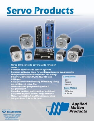
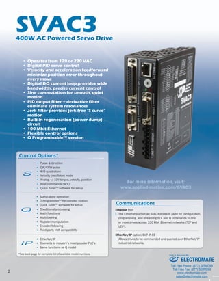
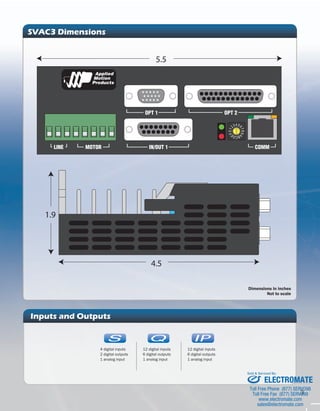
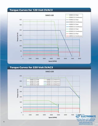
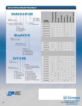

The document discusses servo drive products from Applied Motion, including three drive series (SV7, SVAC3, BLuAC5), common features across the drives, and control options. It provides details on specific drives and motors, including specifications, dimensions, torque curves, and available communications and I/O options. Electromate is listed as the seller and service provider.


![5G Explained! A High Level Overview [Introduction]](https://cdn.slidesharecdn.com/ss_thumbnails/5gexplainedahighleveloverview-260119165306-cc137a3e-thumbnail.jpg?width=640&height=640&fit=bounds)


