

Recommended
Recommended
More Related Content
What's hot
What's hot (20)
Similar to QuickSilver Controls QCI-DS026 QCI-S2-IG
Similar to QuickSilver Controls QCI-DS026 QCI-S2-IG (20)
More from Electromate
More from Electromate (20)
Recently uploaded
Recently uploaded (20)
QuickSilver Controls QCI-DS026 QCI-S2-IG
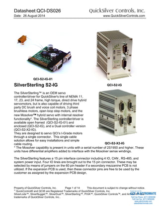
- 1. Datasheet:QCI-DS026 QuickSilver Controls, Inc. Date: 26 August 2014 www.QuickSilverControls.com Property of QuickSilver Controls, Inc. Page 1 of 14 This document is subject to change without notice. QuickControl® and QCI® are Registered Trademarks of QuickSilver Controls, Inc. SilverLode™, SilverNugget™, SilverDust™, SilverSterling™, PVIA™, QuickSilver Controls™, and AntiHunt™ are trademarks of QuickSilver Controls, Inc.. SilverSterling S2-IG The SilverSterling™ is an OEM servo controller/driver for QuickSilver's line of NEMA 11, 17, 23, and 24 frame, high torque, direct drive hybrid servomotors, but is also capable of driving third party DC brush and voice coil motors, 3 phase brushless motors, open loop step motors, and the new Mosolver™ hybrid servo with internal resolver functionality*. The SilverSterling controller/driver is available open framed (QCI-S2-IG-01) and enclosed (QCI-S2-IG), and a Dual controller version (QCI-S2-X2-IG). They are designed to servo QCI’s I-Grade motors through a single connector. This single cable solution allows for easy installations and simple cable routing. * The Mosolver capability is present in units with a serial number of 2S1950 and higher. These units have differential amplifiers added to interface with the Mosolver sense windings. The SilverSterling features a 15 pin interface connector including 4 IO, CAN , RS-485, and system power input. Four IO lines are brought out to the 15 pin connector. These may be selected by means of jumpers on the 60 pin header if a secondary mezzanine PCB is not utilized. If the expansion PCB is used, then these connector pins are free to be used by the customer as assigned by the expansion PCB design. QCI-S2-IG-01 QCI-S2-X2-IG QCI-S2-IG ELECTROMATE Toll Free Phone (877) SERVO98 Toll Free Fax (877) SERV099 www.electromate.com sales@electromate.com Sold & Serviced By:
- 2. Datasheet:QCI-DS026 QuickSilver Controls, Inc. QuickSilver Controls, Inc. Page 2 of 14 The SilverSterling also features a 60 pin header to allow simple and direct connection to expansion boards for both future QuickSilver product extensions and OEM custom interface printed circuit boards, eliminating the need for an additional cable and housing. The 60 pin expansion header includes the ability to bring power to the board as well as access to internal +12v, +5v, and +3.3v power supplies. Access is also provided to two SPI ports (one of which may alternately be used as 4 simple IO), the internal CAN port, 4 configurable analog/digital IO (12 bit A/D), one I2C port (which may be alternately used as 2 IO), A secondary serial port (or alternately 3 I/O), motor encoder signals, one Capture Input (which can also serve as general purpose IO) and an additional 11 general purpose IO. Four connections to the 15 pin control connector are also brought out to the interface connector. Drive capability of each controller is two or three phase at 3.5A RMS / 5A peak. DC Drive capability is 6A (using both output phases connected in parallel). System Overview Point-to-Point Moves Relative or Absolute Velocity or Time Based S-Curve Advanced Motion Profile Moves Profile Move Commands Register Based o Position/Accel/Decel/Vel o Modify On-the-Fly Multi-Axis Linear Interpolation XYZ Coords Contained in Text File CANopen® used for local bus 1000+ Points Stored In NV Memory Built-In Voltage Clamp Regenerative Braking Resistor Program and Data Storage 32K Non-Volatile Memory: 2000-3000 Program Lines User Data Examples o CAM Tables o Motion Profiles o Lookup Tables Electronic Slip Clutch/Brake Variable Torque Wind/Unwind Applications Anti-Hunt™ Optionally use Open Loop While Holding No Servo Dither While At Rest Communications RS-485 @ up to 230K Baud ASCII,Binary,Modbus®,DMX512 Host Control While Servo in Motion CANopen® (Rev 03 SW and higher) Programming Language Easy, Menu Driven Interface Command Parameter Prompts No Syntax Errors User Namable I/O and Registers Advance PVIA™ Servo Loop 100:1 Inertial Mismatch Direct Drive Oversized Inertial Loads o Flywheels/Belt Drives o Typically Without Gearheads More Stable Than PID Digital 4 Quadrant Vector Drive DSP Driven for Reduced Noise Multi-Task/Multi-Thread Compatible with QCI Motor/Encoders NEMA 11 Frame o 4000 Counts/Rev Encoder o Up To 9 oz-in (continuous) NEMA 17 Frame o 8000 Counts/Rev Encoder o Up To 43 oz-in (continuous) o IP50 or IP65 NEMA 23 Frame o 8000 Counts/Rev Encoder o Up To 300 oz-in (continuous) ELECTROMATE Toll Free Phone (877) SERVO98 Toll Free Fax (877) SERV099 www.electromate.com sales@electromate.com Sold & Serviced By:
- 3. Datasheet:QCI-DS026 QuickSilver Controls, Inc. QuickSilver Controls, Inc. Page 3 of 14 Electrical Specifications Configurations The QCI-S2-IG and QCI-S2-IG-01 are single controller units. The QCI-S2-X2-IG contains two independent controllers in a single extruded heatsink; internally there are not connections between the two controllers, and the option of a mezzanine board is not available. Input Power Voltage +12 VDC to +48 VDC, regulated. Device must be initialized for the actual operating voltage. Reverse Polarity Protection Reverse polarity protection is available on the SilverSterling. (Note, however, if power supply is not floating, connecting the V+ input to Ground will cause this potential to be present at the common connection to communications and I/O lines, which may damage these lines or that to which they are connected. Input Current 4.5 Amps maximum for any input voltage, +12 VDC to +48 VDC per controller. Output Power Output/Driver Current 5 Amp peak, 3.5A RMS x 2 phases ; 6 A maximum for DC motors (using both phases in parallel) per controller (restricted to 4.5 A input current - such as driving a lower voltage motor from a higher voltage supply). * With Adequate Heatsink. (4.0A RMS x 2 phases typical 45C rise from 22C, ambient, 3.5A RMS x 2 typical 36C rise from 22C , using QCI-S2-IG heatsink with mounting feet horizontal, still air; Vertical orientation typically several degrees lower. Measurement on outside of heatsink, adjacent to driver.) Maximum Output Power 200 Watts continuous power with adequate heat dissipation, 48V operation. Encoder Interface Designed to work with QCI’s I-Grade motor/encoders. Quadrature differential signals are employed. Quadrature decoding used (i.e 2000 lines are decoded as 8000 counts.) Standard interface is 485 differential inputs. These same differential inputs are also used to interface to the Mosolver sense lines using the Encoder A, A-, B, B- inputs. ELECTROMATE Toll Free Phone (877) SERVO98 Toll Free Fax (877) SERV099 www.electromate.com sales@electromate.com Sold & Serviced By:
- 4. Datasheet:QCI-DS026 QuickSilver Controls, Inc. QuickSilver Controls, Inc. Page 4 of 14 Inputs & Outputs Digital Inputs 0 to +3.3 VDC. LVTTL level compatible. On externally connected IO: Effective internal ~200K ohm pull-up impedance to +3.3 V. Inputs have a series 220 ohm / 3.3v protector to ground / Series 220 ohm ESD protection network. Do not exceed 5v on the inputs to prevent damage to the controller. Internal IO present at header do not have additional protection; user must provide protection needed on expansion PCB. Digital Output Voltage 0 / +3.3 VDC. Digital Output Current Sinking or Sourcing 2mA; (externally connected IO include a 440 series impedance). Analog Inputs 0 to +3.3 VDC input signal range. 12 bit ADC resolution (single). Analog signals are read every servo cycle (120 μsec.) and the converted analog data is processed through a 5 ms filter to reduce noise & transients. Analog channels #1 and #2 are mapped to I/Os #4 and #3, respectively. Mezzanine Connector A 60 pin mezzanine connector has been provided to allow for easy interface to a user specific printed circuit board. Note that the signals on this connector are not protected, and the user must add protection to their circuit board for signals used. If the mezzanine board is not used, pins 20C-20B, 19C-19B, 18C-18B, 17C-17B must be jumpered to access IO1-IO4 at the DB- 15HD SIP connector. (These signals must be connected on the mezzanine board if these functions are wanted at the four IO pins, otherwise other functions can be routed to the four external connections. Note that the Mezzanine connector may be unstuffed on S2-IG units not having a Mezzanine board. Clamp Resistor The QCI-S2 comes with a built in regenerative voltage clamping circuit to prevent damage to the driver from regenerated power associated with stopping a load. The QCI-S2-IG-01 has this clamping resistor attached. The user is responsible for affixing this clamping resistor to a suitable heatsink when installing the PCB. ELECTROMATE Toll Free Phone (877) SERVO98 Toll Free Fax (877) SERV099 www.electromate.com sales@electromate.com Sold & Serviced By:
- 5. Datasheet:QCI-DS026 QuickSilver Controls, Inc. QuickSilver Controls, Inc. Page 5 of 14 Communications Serial Interface RS-485 multi-drop, Reduced unit load accommodates up to 255 nodes. Protected up to +/- 70v not operating, +/-30V operating. Note: RS-485 requires a nominal 120 ohm ½ W termination resistor at each end of the network. This termination is not provided onboard and must be provided by the user. Note: Short runs may work adequately with a higher impedace termination. The S2-IG does not require a biased termination, but other attached devices may require a bias for proper operation. Protocols 8-bit ASCII, 9-bit binary, Modbus, and DMX512 Hardware Configuration Settings Available Baud Rates: 2400, 4800, 9600, 19.2k, 28.8k, 57.6k, 115.2k or 230.4k (250k only for DMX512) Data Bits: 8 (9 bits for binary) Stop Bits: 1.5 or 2 Parity Bit: None (Modbus supports None, Even, Odd) CAN interface The CAN bus connection is NOT isolated, but does include transceivers which have an extended +/- 80v fault protection range. The CANopen® communications protocol allows the unit to function as a master, slave, or peer on a CANopen network. See the SilverLode CANopen User Manual for details on the CANopen protocol. This protocol operates simultaneously and independently from the standard serial protocols. Note that a 120 ohm ½ W termination resistor is required at each end of the CAN network (only two per system). This termination is not provided onboard the controller and must be provided by the user. For the CAN bus, this termination is not optional. CANopen® and CiA® are registered community trade marks of CAN in Automation e.V. STATUS LIGHTS Three status lights are provided on each end of the box. Two sets of status lights are provided to make it easier to see them with the box mounted in different orientations. The Blue Power light indicates power is connected to the unit. The Red COMM LED indicates the unit is ready (no program running) by a dim level, it is off between communications if a program is running. It blinks brightly during each incoming communications frame. The Green Status light varies in intensity with the motor torque (negative torque dimmer, positive torque brighter); if Done Bit is configured the LED lights to indicate Done (See Set Done Bit command), is also used to blink error codes if a fault is detected (and the Done bit is not configured). ELECTROMATE Toll Free Phone (877) SERVO98 Toll Free Fax (877) SERV099 www.electromate.com sales@electromate.com Sold & Serviced By:
- 6. Datasheet:QCI-DS026 QuickSilver Controls, Inc. QuickSilver Controls, Inc. Page 6 of 14 Environmental Specifications Operational Temperature -10 C to +75 C Storage Temperature - 40 C to +85 C Humidity Continuous specification is 95% RH non-condensing. Shock Limitation is approximately 50g/11ms. Specifications subject to change without notice. See www.QuickSilverControls.com for current information. Mounting the QCI-S2-IG-01 The Controller Driver is designed to be mounted between guides that support the edges of the PCB not having LEDs or connectors. The guides should not overlap more than .025 over the edge of the PCB. The driver IC is the tallest device on the back side of the board and defines the distance between the PCB and the heat sink. Two 4-40 nuts are positioned equally about and on the center line of the driver to allow access from the outside of the heatsink to pull the PCB tight to the heatsink. If the third mounting nut (adjacent to the mezzanine connector), an appropriate non-conductive spacer should be used to minimize twisting/flexing of the PCB. The connector plane of the motor and SIP connectors is the reference for alignment and the stabilizer for the connector end of the PCB. Proper ESD handling techniques including grounding straps should be used while handling the open frame printed circuit board to prevent damage. The D-sub shells are grounded and should be the first contact to the PCB as an added measure. THE THERMAL PAD ON THE DRIVER IS INTERNALLY CONNECTED TO THE DRIVER SUBSTRATE AND NEEDS TO BE ATTACHED TO A GROUNDED HEATSINK. Connecting the mounting bracket for the D-sub connectors to the heatsink will provide the needed grounding path. ELECTROMATE Toll Free Phone (877) SERVO98 Toll Free Fax (877) SERV099 www.electromate.com sales@electromate.com Sold & Serviced By:
- 7. Datasheet:QCI-DS026 QuickSilver Controls, Inc. QuickSilver Controls, Inc. Page 7 of 14 Mechnical Dimensions QCI-S2-IG QCI-S2-IG-01 ELECTROMATE Toll Free Phone (877) SERVO98 Toll Free Fax (877) SERV099 www.electromate.com sales@electromate.com Sold & Serviced By:
- 8. Datasheet:QCI-DS026 QuickSilver Controls, Inc. QuickSilver Controls, Inc. Page 8 of 14 QCI-S2-X2-IG ELECTROMATE Toll Free Phone (877) SERVO98 Toll Free Fax (877) SERV099 www.electromate.com sales@electromate.com Sold & Serviced By:
- 9. Datasheet:QCI-DS026 QuickSilver Controls, Inc. QuickSilver Controls, Inc. Page 9 of 14 Connector Data SilverSterling Interface Port (SIP) This port provides Power, RS-485 serial communications, CAN communications, and four IO. It is not backwards compatible with the SilverDust or SilverNugget. The IO is nominally 0-3.3v and should be limited to no more than 5v to avoid damage. The CAN and RS485 have extended input voltage range to improve robustness. Power ground and logic ground are internally connected. Motor Interface QuickSilver Controls recommends our QCI-C-D15P-D15S-nn (nn=length in feet) cable to interface between the motor and controller. Mezzanine Header The Mezzanine Header provides access to additional signals when adding a customer feature board to the S2-IG (Contact factory for custom boards added to box), or S2-IG-01. Four jumpers come standard on the S2-IG to connect the external IO (after input protection network) to the internal IO on the processor. Note that the signals on this connector are not protected and the user must add protection as needed to their customization board in order to use these signals. 7 9 14 15 10 13 12 8 5 4 3 2 11 6 1 12 RS-485B I/O #1 CAN_L I/O #4 15 13 14 +5V OUTPUT 100mA POWER GROUND V+ (12-48 VDC) RS-485A POWER GROUND LOGIC GROUND V+ (12-48 VDC) 6 I/O #2 LOGIC GND (CAN GND) 9 10 11 7 8 CAN_H I/O #3 2 4 5 3 1 14 4 12 11 6 7 13 8 9 2 1 3 15 10 5 6 Motor A + Chassis Ground Encoder Ground Motor Memory Access 13 Encoder B+ 14 15 Motor B - Encoder Z + Motor A - Encoder Z - Encoder A + 10 11 12 8 9 7 Chassis Ground + 5V Encoder Power Motor B+ Encoder A - Encoder B - 3 5 4 1 2 1 10 20 C B A C B A Jumpers to enable IO if no mezzanine board ELECTROMATE Toll Free Phone (877) SERVO98 Toll Free Fax (877) SERV099 www.electromate.com sales@electromate.com Sold & Serviced By:
- 10. Datasheet:QCI-DS026 QuickSilver Controls, Inc. QuickSilver Controls, Inc. Page 10 of 14 Mezzanine Connector Pinout. Contact factory to use additional IO A B C 1 +VP VPsen RxD_A - Primary serial port 2 +VDr = Internal driver voltage +VDr = Internal driver voltage TxD_A - Primary serial port 3 Power Ground (0v) Power Ground (0v) DE_A - Primary serial port 4 +12v @ 10mA +5v @ 100mA RxD_A ENA* (low to disable internal 485) 5 SPIA Slave In Master Out TRST - RESERVED SPIB Slave In Master Out or IO 6 SPIA Slave Out Master In TDI - RED* SPIB Slave Out Master In or IO 7 SPIA Clock TDO - GREEN* SPIB Clock or IO 8 SPIA Chip Select* TMS - Output only SPIB Chip Select* or IO 9 CSO A - Additional Chip select +3.3v @ 100mA RxD_B - Seconadary serial port or IO 10 CAN TX (internal signal) TCLK - Reserved TxD_B - Secondary serial port or IO 11 CAN RX (Internal signal) SDAA - I2C or IO DE_B - Secondary serial port or IO 12 Digital Ground SCLA - I2C or IO ENC_A - buffered from motor encoder 13 ADCINA2 - Digital IO or Analog Digital Ground ENC_B - buffered from motor encoder 14 ADCINB2 - Digital IO or Analog GPIO1 ENC_Z - buffered from motor encoder 15 ADCINA4 - Digital IO or Analog GPIO3 ENC_S - high speed capture of encoder or IO 16 ADCINB4 - Digital IO or Analog GPIO14 CAP_1 - High speed capture or IO 17 No Connect Internal IO4 To SIP pin 14 via protection network, ADC1 via protection 18 No Connect Internal IO1 To SIP pin 13 via protection network 19 3.3v REF Internal IO3 To SIP pin 4 via protection network 20 DRIVE ENABLE (pull low to disable) Internal IO2 To SIP pin 9 via protection network Jumpered by default ELECTROMATE Toll Free Phone (877) SERVO98 Toll Free Fax (877) SERV099 www.electromate.com sales@electromate.com Sold & Serviced By:
- 11. Datasheet:QCI-DS026 QuickSilver Controls, Inc. QuickSilver Controls, Inc. Page 11 of 14 NOTE: GPIOXX pins refer to the processor pin naming convention. IOx pins follow the I/O numbering of the I/O commands within QuickControl. Input Power via Mezzanine Connector Two alternate configurations are available if providing power through the mezzanine connector. The first configuration, shown right, connects the power supply input (12-48V) to Pin 1A referencing power ground on Pins 3A and 3B. Pin 1A connects directly to power pins 1 and 7 of the DB15HD SIP port. Note that the power is then available at the DB15HD SIP connector, so care needs to be taken to prevent anything from touching the supply on the exposed power pins. The connector pin’s current rating must in consideration and must not be exceeded. The internal diodes isolate the supply from the regenerated power, allowing the clamp to operate. The second configuration, shown right, connects the power supply input (12-48V) to +Vdr (Pins 2A & 2B) through a high power Schottky diode. The high power Schottky diode (60V/6A) keeps the internal driver regenerated power from causing the power supply to shut down and enables the clamp circuit to operate properly. It is also necessary to connect a lower power Schottky diode (60V/100mA) from the input power supply to the +VP_S (Pin 1B) to enable proper clamp circuit operation. (Clamp will always be ON if this diode is not present!) Power is isolated from DB15HD SIP port, pins 1&7 with this configuration. ELECTROMATE Toll Free Phone (877) SERVO98 Toll Free Fax (877) SERV099 www.electromate.com sales@electromate.com Sold & Serviced By:
- 12. Datasheet:QCI-DS026 QuickSilver Controls, Inc. QuickSilver Controls, Inc. Page 12 of 14 Recommended Components SilverSterling S2-IG Start-Up Materials For first time users, QCI recommends purchasing the following items to aid with use of the S2- IG controller: 4’ DB15HD Motor I/F Cable (QCI-C-D15P-D15S-04) Breakout Module for SilverSterling (QCI-BO-S1) USB to RS485 converter (QCI-USB-RS485) Desired Motor Optionally: 210W, +48V Power Supply (S-210-48) Power Cable (QCI-C-ACP-FLY-6) Software is free and available from our website. See technical document QCI-TD072 on our website for details. The Standard System detailed below shows a typical installation. SilverSterling S2-IG System ELECTROMATE Toll Free Phone (877) SERVO98 Toll Free Fax (877) SERV099 www.electromate.com sales@electromate.com Sold & Serviced By:
- 13. Datasheet:QCI-DS026 QuickSilver Controls, Inc. QuickSilver Controls, Inc. Page 13 of 14 Accessories: 1. Controller/Driver SilverSterling S2-IG (QCI-S2-IG) is our standard closed frame controller/driver designed to servo QCI’s I-Grade motors through a single connector. 2. Basic Breakout (QCI-BO-S1) QCI recommends purchasing a breakout to simplify wiring power, RS-485 communication, CAN and 4 I/O. The breakouts connect directly to the SilverSterling’s 15-pin interface port (SIP). 3. Motor I/F Cable For standard system, this D-sub type cable goes between the motor and the controller. The generic part number is QCI-C-D15P-D15S-nn. Replace the last two digits “nn” with length of cable in feet (i.e. –10 for 10 feet). Standard lengths are 1, 2, 4, and 10 feet. For IP65 system, a special IP65 cable goes in between the motor and the controller. The motors and cables are IP65, but not the controller/driver. The generic part number is QCI-C-D15P-T14S-nn. Replace the last two digits “nn” with length of cable in feet (i.e. –10 for 10 feet). 4. Motor The SilverSterling S2 is capable of driving any NEMA 11, 17, 23 and 24 I-Grade motor/encoder. See the following datasheets for more information: QCI-DS007: NEMA 17 I-Grade Motor/Encoder QCI-DS008: NEMA 23 I-Grade Motor/Encoder QCI-DS017: NEMA 11 M-Grade Motor/Encoder QCI-DS028: NEMA 24 I-Grade Motor/Encoder QCI-DS029: NEMA 23 Mosolver™ QCI-AN066: BEI voice coil motors with the SilverSterling 5. Power Supply Power supply selection is motor dependent, but the following will work with all the 17 and 23 frame motors. SP-240-48 (48V, 5A, 240 Watt) ELECTROMATE Toll Free Phone (877) SERVO98 Toll Free Fax (877) SERV099 www.electromate.com sales@electromate.com Sold & Serviced By:
- 14. Datasheet:QCI-DS026 QuickSilver Controls, Inc. QuickSilver Controls, Inc. Page 14 of 14 Part Numbers SilverSterling™ IG Controller/Drivers Driver Controller Options QCI-S2-IG: 4 A RMS Per Phase Best paired with I-Grade Motor/Encoders 3.5A RMS per phase 5A peak per phase 4.5A @ 12v-48v Included Clamp circuit and resistor. IG – SilverSterling S2 IG 4 TTL Inputs or Outputs 1 Analog input 1 PWM output ASCII, 9 bit Binary, Modbus®, DMX-512® CANopen® (with Rev 03 sw) DB15HD (pin): SIP Connector DB15HD (socket): Motor I/F X2-IG Two IG controllers in Enclosure Blank – in Heat Sink Enclosure 01 – Board Only Requires user to properly heat sink. V1 – Board Only Motor Port with Vertical DB15HD connector SMI Port with Right Angle DB15HD connector V2 – Board Only Motor Port with Right Angle DB15HD connector SMI Port with Vertical DB15HD connector Example: For IG board only QCI-S2 IG 01 Selection creates part number: QCI-S2-IG-01 Example Part Numbers: QCI-S2-IG QCI-S2-IG-01 QCI-S2-IG-V1 QCI-S2-IG-V2 QCI-S2-X2-IG Contact Information QuickSilver Controls, Inc. 712 Arrow Grand Circle Covina, CA 91722 (626) 384-4760 or (888) 660-3801 (626) 384-4761 FAX www.QuickSilverControls.com ELECTROMATE Toll Free Phone (877) SERVO98 Toll Free Fax (877) SERV099 www.electromate.com sales@electromate.com Sold & Serviced By: