JVL QuickStep Motor with Integrated Driver MIS231,MIS232 and MIS234
•
0 likes•221 views

Product Data Sheet

Recommended
Recommended
More Related Content
What's hot
What's hot (19)
Similar to JVL QuickStep Motor with Integrated Driver MIS231,MIS232 and MIS234
Similar to JVL QuickStep Motor with Integrated Driver MIS231,MIS232 and MIS234 (20)
More from Electromate
More from Electromate (20)
Recently uploaded
Recently uploaded (20)
JVL QuickStep Motor with Integrated Driver MIS231,MIS232 and MIS234
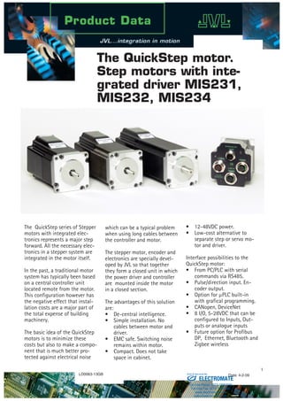
- 1. The QuickStep series of Stepper motors with integrated elec- tronics represents a major step forward. All the necessary elec- tronics in a stepper system are integrated in the motor itself. In the past, a traditional motor system has typically been based on a central controller unit located remote from the motor. This configuration however has the negative effect that instal- lation costs are a major part of the total expense of building machinery. The basic idea of the QuickStep motors is to minimize these costs but also to make a compo- nent that is much better pro- tected against electrical noise The QuickStep motor. Step motors with inte- grated driver MIS231, MIS232, MIS234 which can be a typical problem when using long cables between the controller and motor. The stepper motor, encoder and electronics are specially devel- oped by JVL so that together they form a closed unit in which the power driver and controller are mounted inside the motor in a closed section. The advantages of this solution are: De-central intelligence. Simple installation. No cables between motor and driver. EMC safe. Switching noise remains within motor. Compact. Does not take space in cabinet. • • • • 12-48VDC power. Low-cost alternative to separate step or servo mo- tor and driver. Interface possibilities to the QuickStep motor: From PC/PLC with serial commands via RS485. Pulse/direction input. En- coder output. Option for µPLC built-in with grafical programming. CANopen, DeviceNet 8 I/O, 5-28VDC that can be configured to Inputs, Out- puts or analogue inputs Future option for Profibus DP, Ethernet, Bluetooth and Zigbee wireless • • • • • • • • LD0063-13GB Date: 4-2-09 ELECTROMATE Toll Free Phone (877) SERVO98 Toll Free Fax (877) SERV099 www.electromate.com sales@electromate.com Sold Serviced By:
- 2. Quickstep is a new series of motors from JVL which can be delivered with a large selection of functions and in a wide variety of combinations. The base is a hightorque NEMA23 step motor with a housing so that IP55 or larger protection can be achieved. One or more circuit cards and different con- nectors can be mounted in the housing to adapt the motor to a given task. Also available: Step motor without electronics. Optional with encoder. All modules can be delivered with M12, cable glands or, by larger orders, connector chosen by customer. 1,1Nm, 1,6Nm or 2,9Nm versions Backlash free and planetary gears in ratios of 3, 5, 10, 20, 100 can be deliv- ered from stock. Positioning or Speed Control System and Feature Overview Serial RS485 or 5V serial position controller Position controller with grafic programming, Canbus, CANopen 402 or DeviceNet Stall detect by means of magnetic encoder with resolution of up to 1024 pulses/rev. A double supply facility is avail- able so that position and parame- ters are maintained at emergency stop Gear mode • • • • • Pulse/direction M12 Connector Cable glands MACmotor protocol so MACmotor and Quickstep motors can be con- nected on the same RS485 bus Command for easy PLC/PC setup and communication Power supply 12-48VDC Fixed 1600 pulses/rev. Can also be delivered as box con- troller without motor. Built-in µprocessor with 8 In/Out that can be configured as inputs, PNP outputs or analogue inputs. RS485 interface for set up and program- ming. Option for CANbus, CANopen 402 or Devicenet. Driver technology is improved as compared to SMD73 and supply voltage is 12-48VDC. • • • • • Pulse/direction driver 200, 400, 800, 1000 or 1600 pulse/rev. resolutions. • • Input for pulse/direction signal 5-24VDC PNP/NPN. The driver is the wellknown SMD73. Supply voltage is 12 - 28VDC Can also be delivered as box driver without motor. • • • • ELECTROMATE Toll Free Phone (877) SERVO98 Toll Free Fax (877) SERV099 www.electromate.com sales@electromate.com Sold Serviced By:
- 3. Januar 2004 Modes of Operation Positioning and Velocity Mode In this mode the QuickStep motor positions the motor via com- mands sent over the serial interface. Various operating parameters can be changed continuously while the motor is running. This mode of operation is used primarily in systems where the Controller is permanently connected to a PC/PLC via the interface. This mode is also well suited for setting up and testing systems. The mode is also used when programming is made. Gear Mode In this mode the QuickStep motor functions as in a step motor driver. The motor moves one step each time a voltage pulse is ap- plied to the step-pulse input. Velocity, acceleration and decelera- tion are determined by the external frequency, but can be limited and controlled by the QuickStep motor. In addition, the QuickStep motor also provides a facility for electronic gearing at a keyed-in ratio. Serial Mode In this mode the QuickStep motor’s registers contain the positions, velocities, accelerations, etc., required for the actual system. The registers can be selected and executed by a single byte sent via the serial interface. This mode provides maximum utilisation of the QuickStep motor’s features since the QuickStep motor itself takes care of the entire positioning sequence. Pulse signal QuickStep motor PC/PLC with control- ler modules or pulse generator Operating parameters via serial Interface Selection of register via serial command QuickStep motor Direction signal PC/PLC with e.g. LabWiew or MacTalkQuickStep motor PLC or similar Gear mode Positioning mode Serial mode Analogue signal To other QuickStep motors 2-phase stepper motor 1024 ppr magnetic incremental encoder Optional CVI 12-28V logic P+ 12-48V Bus supply P- Ground IO1 CVO IO8 A- Tx Rx B+ IN1 Analog 1 IN8 Analog 8 Digital 8 Digital 1 CAN L A+ A- B+ B- CAN R Switchmode Power Supply 1/8 step Driver 1600 step/rev. High speed digital logic array Output source driver CAN Tranciever RS422 Optional Optional RS485 driver 16 Bit Microprocessor with Integrated Flash Phase A MotorSMC75 Controller Encoder Phase B Powersupply connectorUserI/Oconnector Serialinterface connector FieldBus connector TT2140GB Fuse 750mA Block Diagrams Positioning/Speed Control versionPulse/Direction version 2-phase stepper motor Incremental encoder Optional A Stepclock Direction SMD73 Driver Motor Encoder B EncoderOutputPowersupplyconnector 200, 400, 800, 1000, 1600 step Driver Bus Supply 12-28V Ground High speed digital logic array Phase A Phase B TT2178GB 5V to 24V PNP/NPN Selector ELECTROMATE Toll Free Phone (877) SERVO98 Toll Free Fax (877) SERV099 www.electromate.com sales@electromate.com Sold Serviced By:
- 4. Setup and programming with software MacTalk MacTalk introduction The MacTalk software is the main interface for setting up the QuickStep motor for a specific application. The program offers the following features: Choice of the operating mode of the QuickStep motor. Changing main parameters such as speed, motor current, zero search • • type, etc. Monitoring the actual motor parameters in real time, such as supply voltage, input status, etc. Changing protection limits such as position limits. Saving all current parameters to disc. Restoring all parameters from disc. Saving all parameters permanently • • • • • in the motor. Updating the motor firmware or MacTalk software from the inter- net or a file. The main window of the program changes according to the selected mode, thus only showing the rel- evant parameters for operation in the selected mode. • Command toolbox description The toolbox used for the programming covers 14 different command types. The idea for the commands - is to have an easy access to the most common functions in the motor. Some func- tions seems to be missing by the first sight but the botton “Set register in the QuickStep motor” or “Wait for a register value before continueing” gives direct access to +50 registers down in the basic QuickStep motor such as the gear ratio or the actual torque register. In total this gives a very power full programming tool since 95% of a typical program can be build using the simple command icons and the last part is optained by accessing the basic motor registers directly. Below is a short description of all 14 command icons. ELECTROMATE Toll Free Phone (877) SERVO98 Toll Free Fax (877) SERV099 www.electromate.com sales@electromate.com Sold Serviced By:
- 5. Torque versus speed Min. Max. Absolute Max. Unit P+ 12 48 - VDC CVI 12 28 32 VDC CVI no out- put activated 95@24VDC mA Motor Current 0 3 3 A RMS Input Logic Low -0.5 0.9 VDC Input Logic High 1.9 28 32 VDC Output Logic High 12 28 32 VDC Analogue Input 0 5 32 VDC Output Current 350* mA *8 Outputs: Totally max. 800 mA. for all 8 outputs active Motor Specifications Quickstep and MAC motor in an RS485 or CANbus network Accessories Motor Type MIS231 MIS232 MIS234 Unit Max. Speed 1000 1000 1000 RPM Rated Torque 1.1 1.6 2.9 Nm Inertia 0.3 0.48 0.96 kgcm2 Length 96.0 118.5 154.0 mm Weight 0.9 1.2 1.8 kg (Position control) RS485-M12-1-5 cable for M12, 5pin to RS485 USB. 5m RS485-USB-ATC-820 USB to RS485 adaptor. 0.5m WI1000-M12xxVxxN M12, angled female/ male cable can be deliv- ered. See cable data- sheet for details. WI1000-M12xxTxxN M12, straight female/ male cable can be deliv- ered. See cable data- sheet for details. PSU24-075 PSU 24VDC/3.2A, 75W. 85-264VAC DIN Switch-mode power supply. UL/CE approved. DIN rail. HxDxW = 126x100x56mm. PSU48-240. PSU48VDC/5A. 240W. 100-240 VACSwitch- mode power supply. UL/CE approved. DIN rail. HxDxW = 126x100x126mm. MAB23X-03. Brake 24V for NEMA23. ø6.35. M8/5m MacTalk MAC motor Windows software for setup and programming MacRegio Windows software for protocol analyses and understanding. MACCOMM OCX/active x driver for Windows programs Quickstep motor torque versus speed and supply voltage 0 0,5 1 1,5 2 2,5 3 3,5 0 100 200 300 400 500 600 700 800 900 1000 Speed (RPM) Torque (Nm) 0 70,8 141,6 212,4 283,2 354 424,8 495,6 MIS234 @48V MIS234 @24V MIS232 @48V MIS232 @24V MIS23 @48V MIS23 @24V Power supply = PSU24-240 (24V/240W regulated PSU) Power supply = PSU48-240 (48V/240W regulated PSU) Room temperature = 20°C Torque (Oz./Inch) ELECTROMATE Toll Free Phone (877) SERVO98 Toll Free Fax (877) SERV099 www.electromate.com sales@electromate.com Sold Serviced By:
- 6. QUICKSTEP M12 connector overview Power Male 5pin IO1-4/RS485 Female 8pin IO5-8 Female 8pin RS485 Female 5pin CANOpen/DeviceNet Male 5pin SSI Encoder Male 8pin Function #MIS23xAzM2yy75 X X RS485, 4IO MIS23xAzM3yy75 X X X 2xRS485, 4IO #MIS23xAzM4yy75 X X X RS485, 8IO MIS23xAzM5yy75 X X X X 2xRS485, 8IO MIS23xAzM6yy75 X X X X CANOpen, RS485 8IO #MIS23xAzM7yy75 X X X X Devicenet, RS485 8IO MIS23xAzM9yy75 X X X X SSI, 6IO M12 Pin 1 P+ (12-48VDC) IO1 IO5 B+ (RS485) CAN_SHLD IO5 Zero Setting M12 Pin 2 P+ (12-48VDC) IO2 IO6 A- (RS485) CAN_V+ IO6 Counting Direction M12 Pin 3 P- (GND) IO3 IO7 B+ (RS485) CAN_GND A+ (Clock+) M12 Pin 4 CVI (12-28VDC) GND IO- GND IO- A- (RS485) CAN_H GND M12 Pin 5 P- (GND) B+ (RS485) GND CAN_L B- (Data in-) M12 Pin 6 - A- (RS485) - - B+ (Data in+) M12 Pin 7 - IO4 IO8 - - A- (Clock-) M12 Pin 8 - CVO (Out) CVO (Out) - - CVO+ (Out) M12 connector solder terminals WI1008- M12F5SS1 WI1008- M12M8SS1 WI1008- M12M8SS1 WI1008- M12M5SS1 WI1008-M12F5SS1 WI1008- M12M8SSI M12 cables 5m. WI1000- M12F5T05N WI1000- M12M8T05N WI1000- M12M8T05N WI1000- M12M5T05N WI1006- M12F5S05R WI1000- M12M8T05N # : Only 50 pcs order . x: 1: 1Nm, 2:1.6Nm, 3: 2,5Nm. z: 1: 6,35mm shaft 3:10,0mm shaft (only if x=3) yy:=NO~No encoder. H2~built-in encoder Versions with pulse and direction control: Connections for versions with 1 pcs M12 connector(See also SMD73 datasheet): M12 5pin male Description 1 P+ (18-28VDC) 2 Pulse 3 P- 4 Direction 5 Signal Ground Color code Description Red P+ (8-28VDC) Black P- Blue Direction White Pulse Shield Signal ground Versions with positioning and speed control: Connections for versions with cable glands and 5 m cable5-pole connector Pin no. Color 1 Brown 2 White 3 Blue 4 Black 5 Grey 8-pole connector Pin no. Color 1 White 2 Brown 3 Green 4 Yellow 5 Grey 6 Pink 7 Blue 8 Red TT2260GB PWR PWR PWRPWR PWR: RS485: CAN: I/O1-4: I/O5-8:5 pin male 5 pin female 5 pin male 8 pin female 8pin female # MIS23xAz yy75M2 RS485 serial communication and few local I/O. MIS23xAz yy75M5 RS485 serial communication in network. Up to 32 MAC and Quickstep on the same network. Many local I/O. MIS23xAz yy75M6 RS485 and CANOpen/Devicenet operation. Many local IO. MIS23xAz yy75M7 MIS23xAz yy75M3 RS485 serial communication in network. Up to 32 MAC and Quickstep on the same network. Few local I/O. # MIS23xAz yy75M4 RS485 serial communication and many local I/O. I/O5-8 I/O5-8 I/O5-8 I/O1-4 RS485 I/O1-4 RS485 CAN I/O1-4 RS485 I/O1-4 RS485 RS485 RS485 PWR I/O1-4 RS485 PWR MIS23xAz yy75M9 RS485 and SSI encoder. Few local I/O. SSI I/O1-4 RS485 RS485 ELECTROMATE Toll Free Phone (877) SERVO98 Toll Free Fax (877) SERV099 www.electromate.com sales@electromate.com Sold Serviced By:
- 7. Motortype Size Generation IPandshaft Connection Feedback DriverTechnology StepResolution mAindriver Inputformat Standbycurrentratio MIS 232 A 1 M2 N0 73 8 10 E 3 1 to 31 Standby current ratio(03 = 1/3 standby current) # D 24V NPN inputs E 24V PNP inputs F 5V inputs xx xx specify mA*100/phase. See SMD73 datasheet 0 No driver # 1 1/1 step (with 200 steps/rev. motor 200 pulses/rev.) 2 1/2 step (with 200 steps/rev. motor 400 pulses/rev.) 4 1/4 step (with 200 steps/rev. motor 800 pulses/rev.) 5 1/5 step (with 200 steps/rev. motor 1000 pulses/rev.) 8 1/8 step (with 200 steps/rev. motor 1600 pulses/rev.) 73 SM73 driver 15-28VDC. Pulse and direction driver 74 Driver 12-48VDC based on SMC75 technology. (Future option). 75 SMC75 driver and controller with FLEXMAC protokol. 12-48VDC and optional encoder/hall sensor feedback. (Future option). # 76 Controller based on SMD41 driver and SMC75 indexer functionality. # 41 SMD41 driver technology, 20-80VDC. Pulse and direction driver. (Future option). 42 SMD42 driver technology, 30-160VDC. Pulse and direction driver. (Future option). N0 No feedback H1 Hall sensor feedback. 32 pulses/rev. Only if driver support this feature (Future option). H2 Hall sensor feedback. 256 pulses/rec. Only if driver supports this feature (from Q4 06) E1 Encoder feedback. 1024 lines = 4096 pulses/rev. Only if driver support this feature. (Future option). M1 M12 1pcs. 5pin male . SMD73 pulse/direction driver. M2 M12 2 pcs. 5 pin male (power). 8 pin female (RS485, 4IOA) M3 M12 3 pcs. 5 pin male (power), 8 pin female (RS485, IOA 1-4), 5 pin female (RS485) M4 M12 3 pcs. 5 pin male (power), 8 pin female (RS485, IOA 1-4), 8 pin female (5V seriel, IOA5-8) M5 M12 4 pcs. 5 pin male (power), 8 pin female (RS485, IOA 1-4 ), 5 pin female (RS485), 8 pin female (5V serial, IOA 5-8). M6 M12 4 pcs. 5 pin male (power), 8 pin female (RS485, IOA 1-4), 8 pin female (5V serial, IOA 5-8), 5 pin male (CANopen ) M7 M12 4 pcs. 5 pin male (power), 8 pin female (RS485, IOA 1-4), 8 pin female (5V serial, IOA 5-8), 5 pin male (DeviceNet ) W0 PG16 and no cable W1 PG16 and 2m cable. Flying leads with shield. EX Long hosing ready for MAC00-xx expansion board (Future option) 1 6,35mm shaft and IP42 2 6,35mm shaft and IP55 (motor shaft and body) IP65 (Rear end and connector) 3 10,0 mm shaft and IP42 4 10,0mm shaft and IP55 (motor shaft and body) IP65 (Rear end and connector) 5 14mm shaft and IP42 6 14mm shaft and IP55 (motor shaft and body) IP65 (Rear end and connector) A Motordriver for 3,0A/phase B Motordriver for 6A/phase (Future option) 230 NEMA23 step motor 231 NEMA23 step motor 232 NEMA23 step motor 234 NEMA23 step motor 340 NEMA34 step motor (From Q4 2006) 341 NEMA34 step motor (From Q4 2006) 342 NEMA34 step motor (From Q4 2006) MIS MISxxx Motor Integrated Stepper motor. Examples MIS 231 A 1 W1 N0 73 8 25 D Motor 6,35 shaft, flying leads, SMD73 driver MIS 234 A 3 M1 N0 73 2 30 D Motor 10mm shaft, M12 , SMD73 MIS 232 A 1 M3 N0 75 Motor 6,35mm shaft. SMC75. 3 pcs M12 connectors MIS 234 A 3 M6 N0 75 Motor 10mm shaft. SMC75. 4 pcs M12 connectors, CANopen MIS 232 A 1 M7 H2 75 Motor 6,35mm shaft. SMC75 .4 pcs M12 connectors. DeviceNet. Encoder H2 option MIS 340 B 5 M1 N0 41 Motor 14,0 mm shaft. 1 pcs M12 connectors. 80V driver MIS 342 B 5 M7 N0 76 Motor 14,0 mm shaft. 4 pcs M12 connectors. 80V controller. DeviceNet. Encoder H2 option # : End of number. No more letters or numbers should be added. Ordering Information ELECTROMATE Toll Free Phone (877) SERVO98 Toll Free Fax (877) SERV099 www.electromate.com sales@electromate.com Sold Serviced By:
- 8. JVL Industri Elektronik A/S Blokken 42 DK-3460 Birkerød, Denmark Tel: +45 4582 4440 Fax: +45 4582 5550 E-mail: jvl@jvl.dk www.jvl.dk 20,6 ±0.5 ∅38.1±0.025 Shaftdia.D 1.6 5.0 54.5 47 ± 0.2 56.4 47±0.2 56.4 4 x Ø5.0 Ø66.67 Motor Type Length ±2mm Length including connector and plug MIS231 96.0 140 MIS232 118.5 162.5 MIS234 154.0 198 Motor Type D (dia.) +0/-0.013 MIS231 6.35 MIS232 6.35 MIS234 10.0 60.0 66.0 Fa Fr (All dimensions in mm). 44 Mechanical dimensions Get started quickly! Starter Kit (MIS231A1M5N075KIT): Contains all necessary parts to get started The kit consists of: Motor, Power Supply, Software, Cables etc. PA0160 - Test box with (I/O and encoder emulation. WI0036 - Cable between test box and QuickStep motor. MIS231A1M5N075 - Integrated step motor. RS485-M12-1-5-5 - cable between QuickStep motor and USB converter. RS485-USB-ATC-820 USB to RS485 adaptor. PSU024-060-M12 - 24 VDC Power supply. 60W. MacTalk - Windows software for setup and programming. Planetary and cycloidal gearheads • Sealed Ball Bearings • High Reliability, High Efficiency Design • NEMA Mounting Standards • High Shaft Loading Capacity • Low Backlash Design • Strong, Caged Roller Bearings • Precision Input Pinion with Balanced Clamp Collar L1: Gear length incl. flange, D2: Gear housing diameter, D2:Output shaft diameter Model. Back- lash [arc min] Gear ratio Effi- ciency [%] Rated torque 10000 Hours [Nm] Emerg stop Torque [Nm] Inertia at motor shaft [kg*cm2 ] Noise [dB(A)] Radial load @12mm [N] Axial load [N] Weight [kg] L1 [mm] D1 [mm] D2 [mm] (h7) HTRG05N003MHN23106J 15 3 97 12 40 0.28 70 500 600 1.0 68 55 12 HTRG05N005MHN23106J 15 5 97 15 45 0.17 70 500 600 1.0 68 55 12 HTRG05N012MHN23106J 15 12 94 20 60 0.16 70 500 600 1.2 84.8 55 12 HTRG05N020MHN23106J 15 20 94 20 60 0.16 70 500 600 1.2 84.8 55 12 HTRG05N100MHN23106J 15 100 90 20 60 0.11 70 500 600 1.5 98.6 55 12 HSPG60-35-SAA-N23 1 35 90 37 74 0.006 - 2600 3700 1.34 71.8 63 34 HSPG80-97-SAA-N23 1 97 90 78 156 0.027 - 4800 6900 2.10 78.8 80 46 HTRG type gears: HSPG type gears: 8 4xM5 holes 142.5 2.5 3 24.5 L1 18 4xM5 14 47 60 NEMA 23 flange D1 ∅ 32 h7 D2 TT2009GB r=20 D1 TT2010GB D2 59 ∅48 ∅86 L1 51.5 42 6 All dimensions in mm ELECTROMATE Toll Free Phone (877) SERVO98 Toll Free Fax (877) SERV099 www.electromate.com sales@electromate.com Sold Serviced By: