JVL AC-Servo Motor with Integrated Driver MAC50, 95, 140 and 141
•
1 like•184 views

Product Data Sheet

Recommended
Recommended
More Related Content
What's hot
What's hot (19)
Similar to JVL AC-Servo Motor with Integrated Driver MAC50, 95, 140 and 141
Similar to JVL AC-Servo Motor with Integrated Driver MAC50, 95, 140 and 141 (20)
More from Electromate
More from Electromate (20)
Recently uploaded
Recently uploaded (20)
JVL AC-Servo Motor with Integrated Driver MAC50, 95, 140 and 141
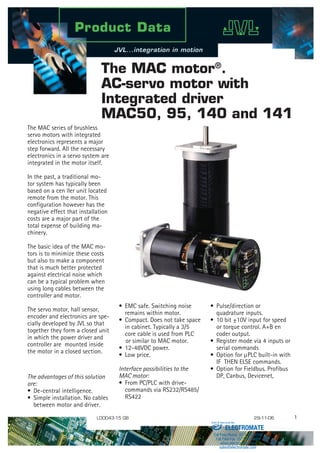
- 1. The MAC motor® . AC-servo motor with Integrated driver MAC50, 95, 140 and 141 The MAC series of brushless servo motors with integrated electronics represents a major step forward. All the necessary electronics in a servo system are integrated in the motor itself. In the past, a traditional mo- tor system has typically been based on a cen ller unit located remote from the motor. This configuration however has the negative effect that installation costs are a major part of the total expense of building ma- chinery. The basic idea of the MAC mo- tors is to minimize these costs but also to make a component that is much better protected against electrical noise which can be a typical problem when using long cables between the controller and motor. The servo motor, hall sensor, encoder and electronics are spe- cially developed by JVL so that together they form a closed unit in which the power driver and controller are mounted inside the motor in a closed section. The advantages of this solution are: • De-central intelligence. • Simple installation. No cables between motor and driver. • Pulse/direction or quadrature inputs. • 10 bit ±10V input for speed or torque control. A+B en coder output. • Register mode via 4 inputs or serial commands • Option for µPLC built-in with IF THEN ELSE commands. • Option for Fieldbus. Profibus DP, Canbus, Devicenet, LD0043-15 GB 29-11-06 • EMC safe. Switching noise remains within motor. • Compact. Does not take space in cabinet. Typically a 3/5 core cable is used from PLC or similar to MAC motor. • 12-48VDC power. • Low price. Interface possibilities to the MAC motor: • From PC/PLC with drive- commands via RS232/RS485/ RS422 ELECTROMATE Toll Free Phone (877) SERVO98 Toll Free Fax (877) SERV099 www.electromate.com sales@electromate.com Sold Serviced By:
- 2. The MAC motor can be con- trolled with ±10V for speed or torque control with encoder feedback to one master motion controller. Furthermore the MAC motor can replace an arbitrary step or ser- vo system, being based on pulse and direction signals. There is a built-in electronic gear so that the MAC motor can simulate all possible step resolutions. The MAC motor can thus replace all step- and servo-systems without change in the PLC/PC/ controller software. Adaptation/ replacement of existing step motor/servo systems can there- fore be achieved quickly. Parameters are set up via the RS232 port from a Windows program. The supply voltage is 24VDC which is industry standard. The motor can be delivered in 3 models: 46, 92 or 134W. A NEMA23 flange is standard so that the MAC motor can replace a step motor directly without mechanical changes. The connector can be chosen as DSUB, Phoenix connector, Mili- tary plug or cable out. Backlash free and planetary gears in ratios of 3, 5, 10, 20, 100 can be delivered from stock. System and feature overview ELECTROMATE Toll Free Phone (877) SERVO98 Toll Free Fax (877) SERV099 www.electromate.com sales@electromate.com Sold Serviced By:
- 3. Modes of Operation (Basic Motor) Gear Mode In this mode the MAC motor functions as in a step motor system. The motor moves one step each time a voltage pulse is applied to the step-pulse input. Velocity, acceleration and deceleration are determined by the external frequency. Use of an encoder enables monitoring and adjustment during motor operation — a feature that is not possible with a standard step motor system. In addition, the MAC motor also provides a facility for electronic gearing at a keyed-in ratio with analogue speed offset. Positioning Mode In this mode the MAC motor positions the motor via commands sent over the RS422 or serial interface. Various operating param- eters can be changed continuously while the motor is running. This mode of operation is used primarily in systems where the Control- ler is permanently connected to a PC/PLC via the interface. This mode is also well suited for setting up and testing systems. Serial Mode (FastMac) In this mode the MAC motor’s registers contain the parameter sets, positions, velocities, etc., required for the actual system. The registers can be selected and executed by a single byte sent via the serial interface. This mode provides maximum utilisation of the MAC motor’s features since the MAC motor itself takes care of the entire positioning sequence. Velocity / Torque Mode In this mode the MAC motor controls the motor velocity/torque via the analogue input. This mode is typically used for simple tasks or for applications in which an overall unit, such as a PC-board or PLC, controls velocity and positioning. Encoder A and B signals can be connected to the overall controller to close the servo loop. Pulse signal MAC motor PC/PLC with control- ler modules or pulse generator Operating parameters via RS 232/485 Interface Selection of register via serial command MAC motor analog ±10V MAC motor e.g. PC-board as overall controller Direction signal PC/PLC with e.g. LabWiew or MacTalk MAC motor PLC or similar Gear mode Positioning mode Serial mode (FastMac) Encoder signal Analogue signal To other MAC motors Velocity/Torque mode Torque versus speed TT2005GB = Peak Torque = Average Torque Operation above 4000 RPM can be done, but the losses in the motor make it impossible to operate in this area continously Please notice that 2700 RPM is the maximum recommended speed for the MAC141. Conditions: Supply voltage = 48VDC Ambient temperature = 20°C Torque setting = 100% Load setting = 1.0 Nm Oz./Inch Oz./InchNm 1000 1000 1.0 142 1421.0 0.8 113 1130.8 0.6 85 850.6 0.4 57 570.4 0.2 28 280.2 0 0 2000 2000 3000 3000 4000 4000 RPM RPM MAC50 Torque versus speed MAC95 Torque versus speed Oz./Inch Oz./Inch Nm Nm 1000 1000 142 248.5 1.0 1.75 113 213 0.8 85 177.5 142 0.6 57 106.5 71 0.4 28 35.5 0.2 0 0 2000 2000 3000 30002700 Operation above 2700 RPM is not recommended. 4000 4000 RPM RPM MAC140 Torque versus speed MAC141 Torque versus speed ELECTROMATE Toll Free Phone (877) SERVO98 Toll Free Fax (877) SERV099 www.electromate.com sales@electromate.com Sold Serviced By:
- 4. Software, MacTalk Block diagram 3-phase brushless motor 1024(2000) ppr optical incremental encoder Hall elements +12-48VDC (+24V and 90-240VAC) Ground AIN Analogue input ±10V A+ A B+ B Output 1 Output 2 Transmit Ground ( ) = Valid for MAC400 and MAC800 Receive +5VDC Out Switchmode Power Supply Power Dump for absorbing regenerative energy 3-phase driver Current Sensing High speed A/D converter High speed digital logic array Analogue input Level shifter and filter 2 channel differential Transceiver Asynchronous serial interface Memory and system control 2 Digital NPN outputs showing motor status 16 (32) Bit Microprocessor A HU HV B W V U HW Powersupply connector(s)UserI/Oconnector Serialinterface connector Basic MAC motor block diagram including motor and feedback devices TT2002GB Startup mode The basic functionality of the MAC motor is setup in this field. Setup save/open The complete setup can be either saved or reloaded from a file using these buttons System control Use these buttons to save data permanently, reset the motor etc. Error Handling Use these fields to define error limits for the position range etc. Input/Outputs The functionality of the I/O's is specified here. Motor status This field shows the actual motor load, position and speed etc. Errors If a fatal error occurs, information will be displayed here.Profile Data All the main para- meters for control- ing the motor behaviour are setup in this field. Zero Search All the parameters regarding the position zero search can be specified here. Undervoltage handling Determine what must happening if the supply voltage gets too low.. MAC motor connection information Always shows if the motor is on line or not. Inputs This field shows the actual supply voltage, the speed at the pulse input and the voltage at the analogue input. TT0914GB ELECTROMATE Toll Free Phone (877) SERVO98 Toll Free Fax (877) SERV099 www.electromate.com sales@electromate.com Sold Serviced By:
- 5. Expansion modules MAC00-FR4 High Speed Multi-axis Module w. M12 connec- tors: RS485 bus w/up to 255 axes. • Multiaxis operation • Compatible with SMCopen IEC 61131-3 automation software • Advanced motion profiles for robot and xyz tables • 4I/4O for user purposes • Open hardware with PIC18F6520 for own sw. • Dual supply support for MAC50-141 MAC00-CS Low cost module, connection directly to basic motor, serial communication not RS232. • Low cost module • Cable connected directly to basic motor connector • User I/O connection • 10 or 20 meter cable • NPN outputs MAC00-B1 General purpose module w/ Sub-D connectors: • Ideal for pulse/direction, ±10V input or RS232/422/485 interface • Standard D- Sub conn. • Home switch input • LEDs to indicate status, Home switch status, Input power status • PNP outputs MAC00-B2 General purpose module w/Cable Glands: other- wise same as –B1, but with IP67 protection. MAC00-B4 General purpose module w/M12 connectors: otherwise same as –B1, but with IP67 protection and USB interface. • Dual supply support for MAC50-141 MAC00-R1 Nano-PLC Module w/Sub-D connectors: Stand- alone operation with 8 DI + 4 DO, RS232/485. • Ideal for stand-alone operation with sequential program execution • 8/4 Opto isolated in-/out. 5-30VDC • Outputs up to 200mA. 10-30VDC • LEDs to indicate output status Home+power status • RS232/RS485 interface MAC00-R3 Nano-PLC Module w/Cable Glands: otherwise same as –R1. • IP67 MAC00-R4 Nano-PLC Module w/M12 connectors: otherwise same as –R1. • IP67 MAC00-FS1 High Speed Multi-axis Module w. D-Sub connectors and opto-isolated RS485. • 9.6 - 460.8kbit • Up to 255 axes (with repeaters) • Command broadcast • Pulse input or output • Dual supply support for MAC50-141 MAC00-FS4 As module FS1 but with M12 connectors MAC00-FP2 Profibus Module w/ Cable Glands: Bus, 6 DI + 2 DO and RS232. • Control and setup through 12Mbit/s profibus-DP • Logic I/Os for High speed start/stop In position indication Home switch • LEDs to indicate status • End limit inputs • Dual supply support for MAC50-141 MAC00-FP4 Profibus Module w/M12 connectors: Bus, 4 DI/DO and RS232. • End limit inputs • Dual supply support for MAC50-141 MAC00-FC4 CAN bus Module w/M12 connectors: Bus, 4 DI/DO and RS232. • Control and setup • Logic I/O for high speed start/stop • CANbus/CANopen DS301/DSP402 • Optional with cable bushes (MAC00-FC2) • End limit inputs • Dual supply support for MAC50-141 MAC00-FD4 DeviceNet Module w/M12 connectors: Bus, 4 DI/DO and RS232. • End limit inputs • Dual supply support for MAC50-141 MAC00-FB4 Bluetooth Module w/M12 connectors. Controlled from PC, PDA, Cellphone or PLC with Bluetooth • Standard Bluetooth SPP profile • Pulse input or output • External connector for antenna • Dual supply support for MAC50-141 Basic Modules Bus Modules Programmable Modules High Speed Multi-Axis Modules Wireless Modules The JVL Integrated motors utilizes the unique module concept. Plug in expansion modules adapt the motor to the application. You can choose connector type, D-Sub., cable glands or M12 connectors and you can choose freely between Profibus, DeviceNet, CANopen or nano PLC com- munication. A High Speed and wireless module add to the possibilities. This means that you have possibilities as with no other motors on the market, and also important, you only pay for what you need. Moreover, if you do not find the feature you need, please contact us, and we will develop your own module. All modules can be delivered with or with cables of up to 20m length. ELECTROMATE Toll Free Phone (877) SERVO98 Toll Free Fax (877) SERV099 www.electromate.com sales@electromate.com Sold Serviced By:
- 6. Technical Data GENERAL Technology AC-servomotor with built-in 1024 PPR encoder, hall sensor and 3 phase servo amplifier/controller. Controller capacity MAC50 MAC95 MAC140 MAC141 Rated output @ 4000RPM 46W 92W 134 W 134W Rated Torque RMS (Nm) 0.11Nm 0.22Nm 0.32Nm 0.48Nm Peak Torque (Nm) 0.32Nm 0.62Nm 0.90Nm 1.59Nm Torque @ 200 RPM with 20:1 gear 2.0 Nm 4.1 Nm 6.0Nm 9.0Nm Inertia (kgcm2 ) 0.075 0.119 0.173 0.227 Length (mm) 112 131 153 172 Weight (kg) (without expansion module) 0.6 0.85 1.1 1.33 Speed range 0-4000RPM with full torque @ 48VDC. Max 4000 RPM (0-2700 RPM for MAC141) Amplifier control system Sinusoidal wave PWM control. 15.7kHz switching. Filter 4th order filter with only one inertia load factor parameter to be adjusted. Expert tuning also available Feedback Incremental A and B encoder 4096 CPR. (Physical 1024 PPR ) Input power supply Single supply 12-48VDC. (absolute max. 50VDC) Active/not active (no load) = 3.7W/3.1W Control mode * ±10V Speed and Torque. A+B encoder outputs * Pulse/direction and 90° phase shifted A+B (Incremental). * RS422 or RS232 (5V) position and parameter commands * Gear mode with analog input speed offset + various options * Sensor zero search or mechanical zero search. * Analogue to position. Flange and shaft dimension NEMA23 compatible. Front: 58mm*58mm. Rear: Ø58. Shaft Ø6,35mm POSITION (pulse inputs) Command input pulse Pulse/direction or 90° phase shifted A+B. RS422. Logic 0 ≤2.0V. Logic 1≥3.0V. Max. voltage at A+, A-, B+, B- = 5.5V. Input frequency 0-2.5 MHz or 0-150kHz with input filter Electronic gear A/B: A= -10000 to 10000, B=1 to10000. Simulation of all step resolutions for easy replacement of step motor systems Following error register 32 bit In position width 0-32767 pulse Position range 32 bit. Infinity, Flip over at ±231 pulses. POSITION (serial communication) Communication facility From PLC, PC etc via RS422 or asynchronous serial port RS232 with special cable. MacTalk JVL commands, special commands with high security. Communication baud rate 19200 bit/sec. (19.2kBaud) Position range ±67 000 000 Speed range 0-4000 RPM. Digital resolution 0.477 RPM Acceleration range 248 – 397364 RPM/sec Addressing Point to point on RS422. Up to 32 units on the same serial RS232/RS485 interface with built-in expansion module. Address range 1-254 Number of parameters. Standard 85. With MacRegIO software 156 (Only for experts) Speed variance Max ±4 RPM variance between command and actual speed. SPEED/ TORQUE Analogue speed/torque input. 12 bit. ±10V. 10kOhm input resistance. Voltage range max. –10 to +32VDC. Offset typical ±50mV Analogue input tolerance. Typical ±1%. Max. 5% (Possible to make software adjustment to minimize gain and offset errors) Sampling rate at analogue input 521 Hz Encoder output signals A+,A-,B+,B-, RS422. Line driver 5V outputs (SN75176). 90° Phase shifted. Analogue speed input +voltage - CW rotation. Shaft view Zero speed determination. 0 - rated speed. Speed variance at rated speed Initial error @20°C: ±0.5% Power Supply: ±10%: 0.0% Load 0-300%: ±0.0% Ambient temperature 0-40°C: ±0.1% Torque limit in speed mode 0-300% by parameter Analogue torque input +voltage (positive torque) - CW rotation. Shaft view Torque control accuracy ±10% @ 20°C (Reproducibility) VARIOUS Fatal error brake Controlled deceleration by fatal error. Regenerative Integrated power dump. 3W can be absorbed continuously. External attachment is possible Protective functions. Error trace back. Overload (I2 t), follow error, function error, regenerative overload (over voltage), software position limit. Abnormality in flash memory, under voltage, over current LED functions Power (Green LED), Error (Red LED) Output signals 2 general purpose NPN 30V/25 mA outputs. Error and In position. Zero search 1: Automatic zero search with sensor connected to input (2 formats) 2: Mechanical zero search without sensor. (Torque controlled) Shaft load maximum Radial load: 75N (20mm from flange). Axial load: 15N. Standards CE approved. UL pending Protection IP42 or IP67 (IP55 on request) Usage / Storage Temperature Basic motor connector: (Other functions available with expansion modules) Ambient 0 to +40°C / -20 to +85°C (Humidity 90%) RS232 serial interface IN/OUT: User I/O connector Power 1: +5VDC out 1: Ground 5: A+ MultifunctionI/O 1:P+ 2: Receive Rx (5V) 2: Analog in 6: A- Multifunction I/O 2:P- 3: Transmit Tx (5V) 3: Output1 (Error) 7: B+Multifunction I/O 4: Ground 4: Output2 (In pos.) 8: B- Multifunction I/O ELECTROMATE Toll Free Phone (877) SERVO98 Toll Free Fax (877) SERV099 www.electromate.com sales@electromate.com Sold Serviced By:
- 7. MAC motor selection chart Planetary and cycloidal gearheads • Sealed Ball Bearings • High Reliability, High Efficiency Design • NEMA Mounting Standards • High Shaft Loading Capacity • Low Backlash Design • Strong, Caged Roller Bearings • Precision Input Pinion with Balanced Clamp Collar L1: Gear length incl. flange, D2: Gear housing diameter, D2:Output shaft diameter HTRG type gears: HSPG type gears: Power supply and power dump resistor Large capacitor which absorbs energy returned during deceleration so that it can be reused. If the voltage nevertheless increases to more than about 50VDC, the energy will be dissipated in a built- in power dump resistor. The Power Supply can feed several MAC motors, up to 1000 W total. An external transformer must be con- nected. (hxd: 105 x 65mm) PSU00-PD1 Power Supply Model. Back- lash [arc min] Gear ratio Effi- ciency [%] Rated torque 10000 Hours [Nm] Emerg stop Torque [Nm] Inertia at motor shaft [kg*cm2 ] Noise [dB(A)] Radial load @12mm [N] Axial load [N] Weight [kg] L1 [mm] D1 [mm] D2 [mm] (h7) HTRG05N003MHN23106J 15 3 97 12 40 0.28 70 500 600 1.0 68 55 12 HTRG05N005MHN23106J 15 5 97 15 45 0.17 70 500 600 1.0 68 55 12 HTRG05N012MHN23106J 15 12 94 20 60 0.16 70 500 600 1.2 84.8 55 12 HTRG05N020MHN23106J 15 20 94 20 60 0.16 70 500 600 1.2 84.8 55 12 HTRG05N100MHN23106J 15 100 90 20 60 0.11 70 500 600 1.5 98.6 55 12 HSPG60-35-SAA-N23 1 35 90 37 74 0.006 - 2600 3700 1.34 71.8 63 34 HSPG80-97-SAA-N23 1 97 90 78 156 0.027 - 4800 6900 2.10 78.8 80 46 MAC50,95,140,141-A1 Unbalancedasync. serialinterface Forsetup/sendingcommands Balancedasync. serialinterface Forsetup/sendingcommands ±10VAnalogueinput Forcontrollingspeed/torque Alsousedforzerosearch Pulseinputs Acceptspulseanddirectionor quadratureencodersignal Pulseoutputs 90degreephaseshifted outputsfrominternalencoder Digitaluserinputs Forcontrolofprogramflow ormotorstart/stop Digitaluseroutputs Forindicatingthemotorstatus orasoutputfromtheprogram Ext.connectortype Protectionclass Integratedbrake MAC50,95,140,141-A3 MAC400/800-D2/D5 MAC400/800-D3/D6 MAC00-CS MAC00-B1 MAC00-B2 MAC00-B4 MAC00-R1 MAC00-FC4 MAC00-R3 MAC00-FD4 MAC00-FB4 MAC00-R4 MAC00-FS1 MAC00-FP2 MAC00-FP4 MAC00-FR4 Feature Type Basic MAC motors IP42 Basic MAC motors IP67 Basic MAC motors IP55 or IP65 Basic MAC motors IP55 or IP65 Conn. module w/cable glands No electronic features added Connector module w/DSUB connectors Connector module w/cable glands 2) Nano PLC w/ DSUB connect. CANopen w/M2 connectors Nano PLC w/cable glands 2) Bluetooth module Nano PLC w/M2 connectors Profibus DP w/cable glands 2) Profibus DP w/M2 connectors High speed serial RS485 Multiaxis. Interf. to IEC63- High speed serial RS485 Multiaxis MAC Motors feature overview including expansion modules 5V TTL 9.2kbaud Full Duplex 5V TTL 9.2kbaud Full Duplex 5V TTL 9.2kbaud Full Duplex 5V TTL 9.2kbaud Full Duplex 5V TTL 9.2kbaud Full Duplex RS232 9.2kbaud Full Duplex RS232 9.2kbaud Full Duplex RS232 9.2kbaud Full Duplex RS232 9.2kbaud Full Duplex RS232 9.2kbaud Full Duplex RS232 9.2kbaud Full Duplex RS232 9.2kbaud Full Duplex RS232 9.2kbaud Full Duplex RS232 9.2kbaud Full Duplex RS232 9.2kbaud Full Duplex RS232 9.2kbaud Full Duplex No RS422 9.2kbaud Full Duplex 3) RS422 2.5Mhz or 50kHz (LP) 3) RS422 4096 cpr 3) RS422 4096 cpr 3) RS422 892/ 8000 cpr 3) RS422 892/ 8000 cpr 3) RS422 3) RS422 3) RS422 3) RS422 3) RS422 3) No No No No No No No No No No No No No No No RS422 3) 2.5MHz or 50kHz TT202GB No No 4) 4) 4) No No No No No RS422 3) No No No 6 Inputs Opto isol. 5-30V 4 Inputs Opto isol. 5-30V 4) 6 Inputs Opto isol. 5-30V 4 Inputs Opto isol. 5-30V 4) 6 Inputs Opto isol. 5-30V 4 Inputs Opto isol. 5-30V 4) 6 Inputs Opto isol. 5-30V 4 Inputs Opto isol. 5-30V 4 Inputs Opto isol. 5-30V Motor stat. 2 x NPN 25mA Motor stat. 2 x NPN 25mA Motor stat. 2 x NPN 25mA Motor stat. 2 x NPN 25mA Motor stat. 2 x NPN 25mA 4 Outputs PNP 0-30V 300mA 2 Outputs PNP 0-32V 25mA 4) 2 Outputs PNP 0-32V 25mA 4) 4 Outputs PNP 300mA 0-30V 4 Outputs PNP 300mA 0-30V 2 Outputs PNP 0-32V 25mA Motor status PNP 0-32V 25mA Motor status PNP 0-32V 25mA 4) 4 Outputs PNP 300mA 0-30V Motor stat. PNP 0-32V 00mA Motor stat. PNP 0-32V 00mA Motor stat. PNP 0-32V 00mA Motor stat. PNP 0-32V 00mA AMP Molex JST AMP Molex JST AMP Molex JST AMP Molex JST DSUB Cable Gland M2 Cable Gland Cable Gland M2 Cable Gland M2 M2 M2 M2 M2 DSUB DSUB IP42 IP42 IP67 ) IP67 ) IP42 IP67 ) IP55/ 65 IP55/ 65 IP67 ) IP67 ) IP67 ) IP67 ) IP67 ) IP67 ) IP67 ) IP67 ) IP67 ) IP42 RS422 2.5Mhz or 50kHz (LP) 3) RS422 2.5Mhz or 50kHz (LP) 3) RS422 2.5Mhz or 50kHz (LP) 3) RS422 3) 2.5Mhz or 50kHz (LP) RS422 3) 2.5Mhz or 50kHz (LP) RS422 3) 2.5Mhz or 50kHz (LP) RS422 3) 2.5Mhz or 50kHz (LP) RS422 9.2kbaud Full Duplex 3) RS422 9.2kbaud Full Duplex 3) RS422 9.2kbaud Full Duplex 3) RS422 3) 9.2kbaud Full Duplex RS422 3) 9.2k Full Duplex RS422 3) RS485 9.2k Full Duplex RS422 3) RS485 9.2k Full Duplex RS485 9.2kbaud Half Duplex RS485 9.2kbaud HalflDuplex RS485 9.2kbaud HalflDuplex RS485 460 kBaud Opto isol. No No No No RS485 230kbaud Opto isol. Basic MAC motors Expansion modules ) IP67 protection class is only possible if the basic MAC motor also offers IP67 2) Can be ordered without cable (eg. MAC00-CS) or with cable in metre 2, 0 or 20 (eg. MAC-CS-0). 3) Either pulse input, pulse output or serial must be chosen. Not all of them at the same time. 4) Only a total of 4 I/O terminals are available. Connector module w/M2 connectors RS232 9.2kbaud Full Duplex RS422 3) RS485 9.2k Full Duplex RS422 3) 2.5MHz or 50kHz (LP) 8 4xM5 holes 142.5 2.5 3 24.5 L1 18 4xM5 14 47 60 NEMA 23 flange D1 ∅ 32 h7 D2 TT2009GB r=20 D1 TT2010GB D2 59 ∅48 ∅86 L1 51.5 42 6 All dimensions in mm ELECTROMATE Toll Free Phone (877) SERVO98 Toll Free Fax (877) SERV099 www.electromate.com sales@electromate.com Sold Serviced By:
- 8. JVL Industri Elektronik A/S Blokken 42 DK-3460 Birkerød, Denmark Tel: +45 4582 4440 Fax: +45 4582 5550 E-mail: jvl@jvl.dk www.jvl.dk AC servo motors MAC50, 95, 140 and 141 Ordering information Accessories MAC140 - A 1 Motor Type AC-brushless Rated Output 50: 46W 95: 92W 140:134W 141:134W Protection 1: IP42 3: IP67 (Stainless steel flange+shaft) A: Standard, max. 4000 rpm RS232-9-1 Cable for PC RS232-9-1-Mac Cable for PC with built in RS232 converter MacTalk Software for set-up of Mac motor MacRegIO Software for experts MAC00-00 End cover IP42 without holes MAC00-01 End cover IP67 with 2 cable bushes MAC00-02 End cover IP67 with 4 cable bushes PSU00-PD1 Power dump/Power supply PSU40-4 Power supply, 40VDC/400W, 19”rack TF0001 Transformer 35VAC/400W PSU24-024 Power supply, 24V/1A PSU48-240 Power supply, 48V/240W Mechanical dimensions Get started quickly! Starter Kit (MAC140-A1-KIT): Contains all neccessary parts to get started The kit consists of: Motor, Expansion Module, Software, PC Cable and Power Supply MAC 140-A1 MAC00-B1 MacTalk RS232-9-1 PSU24-024 80.00 Ø59.0 Ø38.1 +0/-0.05 47.15 58.7MaxØ6.35 +0/-0.013 5.5 Max. 20.57 (0.810 ’’) 15.0 47.15 58.7 Max All dimensions in mm Shown without expansion module Rear (Connections) Front (Shaft) 4 x Ø5.2 Max. 1.574 (0.062”) Digital Drive AC-Brushless Servo Motor Standard NEMA23 MAC50-A1 = 111.2 MAC95-A1 = 131.5 MAC140-A1 = 150.5 MAC141-A1 = 172 TT2011GB M2.5 mounting hole for expansion module. M2.5 mounting hole for expansion module. ELECTROMATE Toll Free Phone (877) SERVO98 Toll Free Fax (877) SERV099 www.electromate.com sales@electromate.com Sold Serviced By: