Download to read offline
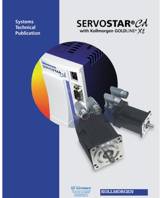


The SERVOSTAR CD amplifier is a compact, fully digital servo amplifier that provides three control algorithms and self-tuning functionality to simplify installation and setup. It utilizes MOTIONLINK software which automatically guides the user through key setup steps. The amplifier provides features such as torque control, velocity control, positioning control, electronic gearing, and fault detection capabilities.


![çõEs Do Controller[1]](https://cdn.slidesharecdn.com/ss_thumbnails/es-do-controller1-1195233868286292-4-thumbnail.jpg?width=640&height=640&fit=bounds)


