Download to read offline
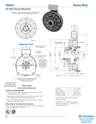
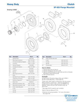

This document provides specifications for a Clutch Heavy Duty SF-825 Flange Mounted clutch. It lists dimensions, torque and speed ratings, voltage compatibility, and part numbers for purchasing. Customers must meet concentricity and squareness tolerances for proper mounting. The document also provides an exploded view diagram of the clutch components and instructions for ordering.


