1. Table Type / Arm Type / Flat Type
Table Type / Arm Type
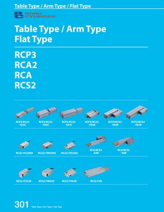
Flat Type
RCP3
RCA2
RCA
RCS2
RCP3/RCA2
-TA3C
RCA2-TCA3NA RCA2-TWA3NA RCA2-TFA3NA
301 Table Type / Arm Type / Flat Type
RCA/RCS2
-A4R
RCP3/RCA2
-TA5C
RCA/RCS2
-A6R
RCP3/RCA2
-TA7C
RCP3/RCA2
-TA3R
RCP3/RCA2
-TA5R
RCP3/RCA2
-TA7R
RCS2-TCA5N RCS2-TWA5N RCS2-TFA5N RCS2-F5D
2. Table Type / Arm Type / Flat Type
Slider
Type
Mini
Standard
Controllers
Integrated
Rod
Type
Mini
Standard
Controllers
Integrated
Table/
Arm/
Flat Type
Mini
Standard
Gripper/
Rotary
Type
Linear
Servo
Type
Clean-room
Type
Splash-
Proof
Type
Pulse
Motor
Servo
Motor
(24V)
Servo
Motor
(200V)
Linear
Servo
Motor
Table Type / Arm Type / Flat Type 302
RCP3
series
Pulse
Motor
Type
Mini Table Type Inline Motor 36mm Width RCP3-TA3C 303
40mm Width RCP3-TA4C 305
Table Type Inline Motor 55mm Width RCP3-TA5C 307
65mm Width RCP3-TA6C 309
75mm Width RCP3-TA7C 311
Mini Table Type Side-Mounted Motor 36mm Width RCP3-TA3R 313
40mm Width RCP3-TA4R 315
Table Type Side-Mounted Motor 55mm Width RCP3-TA5R 317
65mm Width RCP3-TA6R 319
75mm Width RCP3-TA7R 321
RCA2
series
24V
Servo
Motor
Type
Mini Table Type Short-Length Compact Model 32mm Width RCA2-TCA3NA 323
36mm Width RCA2-TCA4NA 325
Short-Length Wide Model 50mm Width RCA2-TWA3NA 327
58mm Width RCA2-TWA4NA 329
Short-Length Flat Model 61mm Width RCA2-TFA3NA 331
71mm Width RCA2-TFA4NA 333
Inline Motor 40mm Width RCA2-TA4C 335
55mm Width RCA2-TA5C 337
Table Type Inline Motor 65mm Width RCA2-TA6C 339
75mm Width RCA2-TA7C 341
Mini Table Type Side-Mounted Motor 40mm Width RCA2-TA4R 343
Table Type Side-Mounted Motor 55mm Width RCA2-TA5R 345
65mm Width RCA2-TA6R 347
75mm Width RCA2-TA7R 349
RCA2
series
24V Servo
Motor Type
Arm Type 40mm Width RCA-A4R 357
52mm Width RCA-A5R 359
58mm Width RCA-A6R 361
RCS2
series
200V Servo
Motor Type
Mini Table Type Short-Length Compact Model 48mm Width RCS2-TCA5N 351
Short-Length Wide Model 80mm Width RCS2-TWA5N 353
Short-Length Flat Model 95mm Width RCS2-TFA5N 355
Arm Type 40mm Width RCS2-A4R 363
52mm Width RCS2-A5R 365
58mm Width RCS2-A6R 367
Flat Type 55mm Width RCS2-F5D 369
3. RCP3 ROBO Cylinder 303 RCP3-TA3C ROBO Cylinder, Mini Table Type, Motor Unit Coupled Type, Actuator Width 36mm,
Series Applicable controller
RCP3-TA3C
Slider
Type
Mini
Standard
Controllers
Integrated
Rod
Type
Mini
Standard
Controllers
Integrated
Table/
Arm/
Flat Type
Mini
Standard
Gripper/
Rotary
Type
Linear
Servo
Type
Clean-room
Type
Splash-
Proof
Type
Pulse
Motor
Servo
Motor
(24V)
Servo
Motor
(200V)
Linear
Servo
Motor
I
20P
Type Lead Stroke Cable length Options
„„Speed vs. Load Capacity
Due to the characteristics of the pulse motor,
the 1.4
RCP3 2mm series' Lead
load capacity decreases at high
speeds. In the table below, check if your desired
speed and load capacity are supported.
Load capacity (Kg) Speed (mm/s) Load capacity (Kg)
0.7
4mm Lead
2
1.75
1.5
1.25
2mm Lead
4mm Lead
0 50 100 150 200 250 300 350
0 50 100 150 200 250 300 350
0.3
1.6
1.4
1.2
1.0
0 50 100 150 200 250 300 350
2
1.75
1.5
1.25
1.0
0.75
0.5
0.25
0
1.0
0.75
0.5
0.25
1.6
1.4
1.2
1.0
0.8
0.6
0.4
0.2
0
Speed (mm/s)
0.7
4mm Lead
6mm Lead
6mm Lead
2mm Lead
Horizontal
Vertical
1.4
0.7
0.3
0 50 100 150 200 250 300 350
0
0.8
0.6
0.4
0.2
0
Speed (mm/s)
Load capacity (Kg)
Speed (mm/s)
Load capacity (Kg)
0.7
4mm Lead
6mm Lead
6mm Lead
2mm Lead
Horizontal
Vertical
Pulse Motor, Ball Screw Specification
Appendix
P.5
6 : 6mm
4 : 4mm
2 : 2mm
(1) The payload is the value when operated with acceleration of 0.3G (or 0.2G in the case of 2mm-lead and
vertical usage). The upper limit for acceleration is 0.3G (or 0.2G in the case of 2mm-lead and vertical usage).
(2) See page A-71 for details on push motion.
Stroke
Stroke
(mm) Standard price
20 —
30 —
40 —
50 —
60 —
70 —
80 —
90 —
100 —
Type Cable symbol Standard price
Standard
(Robot Cables)
P (1m) —
S (3m) —
M (5m) —
Special length
X06 (6m) ~ X10 (10m) —
X11 (11m) ~ X15 (15m) —
X16 (16m) ~ X20 (20m) —
Cable Length
* The standard cable for the RCP3 is the robot cable.
* See page A-59 for cables for maintenance.
Options
Name Option code See page Standard price
Brake B ➝ A-42 —
Non-motor end specification NM ➝ A-52 —
Actuator Specifications
Item Description
Drive System Ball screw, ø6mm, rolled C10
Positioning Repeatability ±0.02mm
Lost Motion 0.1mm or less
Base Material: Aluminum, white alumite treated
Allowable static moment (*) Ma: 3.2 N·m, Mb: 4.6 N·m, Mc: 5.1 N·m
Ambient operating temperature, humidity 0 to 40oC, 85% RH or less (Non-condensing)
(*) Based on 5,000km of traveling life
Directions of allowable load moments
Ma Mb Mc
20P: Pulse motor,
20 size
I: Incremental
* The Simple absolute
encoder is also
considered type "I".
P1: PCON-PL/PO/SE
PSEL
P3: PCON-CA
PMEC/PSEP
MSEP
N: None
P: 1m
S: 3m
M: 5m
X: Custom Length
TA3C
Encoder type
Motor type
Model RCP3
Specification
Items
20: 20mm
100: 100mm
(10mm pitch
increments)
* See page Pre-47 for details on the model descriptions.
See Options below.
Actuator Specifications
„„Leads and Payloads (Note 1) Please note that the maximum load capacity decreases as the speed increases. „„Stroke and Maximum Speed (Unit: mm/s)
* The values enclosed in < > apply to vertical settings.
Model number Feed
Screw
Lead
(mm)
Max. Load Capacity (Note 1) Rated
thrust (N)
Stroke
Horizontal (kg) Vertical (kg) (mm)
RCP3-TA3C-I-20P-6- ➀ - ➁ - ➂ - ➃
Ball
screw
6 ~0.7 ~0.3 15
20~100
RCP3-TA3C-I-20P-4- ➀ - ➁ - ➂ - ➃ 4 ~1.4 ~0.6 22 (every 10mm)
RCP3-TA3C-I-20P-2- ➀ - ➁ - ➂ - ➃ 2 ~2 ~1 45
Stroke 20~100
Lead (mm)
6 300<200>
4 200<133>
2 100<67>
Ball screw
Code explanation ➀ Stroke ➁ Applicable Controller ➂ Cable length ➃ Options *See page A-71 for details on push motion.
4. RCP3 ROBO Cylinder
Slider
Type
Mini
Standard
Controllers
Integrated
Rod
Type
Mini
Standard
Controllers
Integrated
Table/
Arm/
Flat Type
Mini
Standard
Gripper/
Rotary
Type
Linear
Servo
Type
Clean-room
Type
Splash-
Proof
Type
Pulse
Motor
Servo
Motor
(24V)
Servo
Motor
(200V)
Linear
Servo
Motor
CAD drawings can be downloaded
from the website. www.intelligentactuator.com
5
16
3
Applicable Controllers
„„Dimensions and Weight by Stroke
RCP3 series actuators can be operated with the controllers indicated below. Select the type according to your intended application.
Name External
view Model number Features Maximum number of
positioning points
Input
power
Power-supply
capacity
For brake specification:
* The above brake unit is
added to area .
3.5 (Motor height)
* Brake-equipped models
are heavier by 0.1kg.
Standard
price
5
7.4
Reference
page
Solenoid Valve Type
PMEC-C-20PI- -2- Easy-to-use controller, even for beginners
3 points
AC100V
AC200V
Refer to
P541 — ➝ P537
PSEP-C-20PI- -2-0 Simple controller operable with the same
signal as a solenoid valve
DC24V
Refer to
P555 — ➝ P547
PIO specification MSEP-C- -~- -2-0 Positioner type based on PIO control,
24
Solenoid valve multi-axis type
allowing up to 8 axes to be connected Refer to
P572 — ➝ P563
Network specification MSEP-C- -~- -0-0 Field network-ready positioner type,
Solenoid valve multi-axis type
allowing up to 8 axes to be connected 256 points
Positioner type
Equipped with a high-output driver
High-output specification PCON-CA-20PI- -2-0 Positioner type based on PIO control 512 points
Refer to
P618
—
High-output specification PCON-CA-20PI-PL-2-0 Equipped with a high-output driver
Pulse-train type ➝ P607
Pulse-train input type (—) —
Field network type
PCON-CA-20PI- -0-0 Equipped with a high-output driver
High-output specification Supporting 7 major field networks 768 points —
Pulse Train Input Type
(Differential Line Driver) PCON-PL-20PI- -2-0 Pulse train input type with differential line
driver support
(—)
Refer to
P628
—
Pulse Train Input Type ➝ P623
(Open Collector) PCON-PO-20PI- -2-0 Pulse train input type with open collector
support —
Serial Communication Type PCON-SE-20PI-N-0-0 Dedicated Serial Communication 64 points —
Program
Control Type PSEL-CS-1-20PI- -2-0 Programmed operation is possible.
Can operate up to 2 axes 1,500 points Refer to
P671 — ➝ P665
* This is for the single-axis PSEL. * indicates I/O type (NP/PN). * indicates power supply voltage (1: 100V / 2: 100~240V).
* indicates number of axes (1 to 8). * indicates field network specification symbol. * indicates N (NPN specification) or P (PNP specification) symbol.
(Connector width)
RCP3-TA3C 304
3-M4
Depth 6mm 24
10
33
36
4.5
41
ø3H7 Depth 3.5mm
(From the table top)
12 Gx40 H-M3 Depth 5mm
Motor/encoder
Cable connector*1
3H7 Depth 3.5mm
(From the table top)
40
(Reamer and oblong hole pitch)
4
38
32
29
3
7.5
30
18
L Allow for at least 100mm
102.5
26
23
Home ME *2
8
ST
ME SE
12 18.5
30.6
A
B
C
D
3H7 Depth 3.5mm
(from the bottom of
the base)
4
50
J-M3 (Reamer and oblong hole pitch)
Depth 5mm
28
ø3H7 Depth 3.5mm
(From the bottom of the base) 5 Ex50 F 7.5
A
A
10.5
28.5
Reference position
for the moment o set
Dimensional Drawings
Appendix
P.15
2D
CAD
Stroke 20 30 40 50 60 70 80 90 100
L Without brake 224 234 244 254 264 274 284 294 304
With brake 262 272 282 292 302 312 322 332 342
A 87.5 97.5 107.5 117.5 127.5 137.5 147.5 157.7 167.5
B 95.5 105.5 115.1 125.5 135.5 145.5 155.5 165.5 175.5
C 121.5 131.5 141.5 151.5 161.5 171.5 181.5 191.5 201.5
D 91 101 111 121 131 141 151 161 171
E 1 1 1 1 2 2 2 2 2
F 28.5 38.5 48.5 58.5 18.5 28.5 38.5 48.5 58.5
G 1 1 1 1 2 2 2 2 2
H 4 4 4 4 6 6 6 6 6
J 6 6 6 6 8 8 8 8 8
Weight (kg) 0.5 0.5 0.5 0.6 0.6 0.6 0.6 0.7 0.7
(*1) Connect the motor-encoder integrated cable here. See page A-59 for details on cables.
(*2) After homing, the slider moves to the ME, therefore, please watch for any interference
with surrounding objects.
ST : Stroke
ME : Mechanical end
SE : Stroke end
5. RCP3 ROBO Cylinder 305 RCP3-TA4C ROBO Cylinder, Mini Table Type, Motor Unit Coupled Type, Actuator Width 40mm,
Series Applicable controller
RCP3-TA4C
Slider
Type
Mini
Standard
Controllers
Integrated
Rod
Type
Mini
Standard
Controllers
Integrated
Table/
Arm/
Flat Type
Mini
Standard
Gripper/
Rotary
Type
Linear
Servo
Type
Clean-room
Type
Splash-
Proof
Type
Pulse
Motor
Servo
Motor
(24V)
Servo
Motor
(200V)
Linear
Servo
Motor
I
28P
Type Lead Stroke Cable length Options
„„Speed vs. Load Capacity
Due 3.0
to the 2mm characteristics Lead
Horizontal
of the pulse motor,
the RCP3 series' 2.5
load capacity decreases at high
speeds. In the table below, check if your desired
speed and load capacity are supported.
Load capacity (Kg) Load capacity (Kg) Speed (mm/s)
4mm Lead
2mm Lead
2.5
1.5
Horizontal
1.0
0.7
6mm Lead
0 50 100 150 200 250 300 350
1.5
3.0
1.0
0.7
4mm Lead
6mm Lead
3.2
2.8
2.4
2.0
1.6
1.2
0.8
0.4
0
Speed (mm/s)
0 50 100 150 200 250 300 350
Speed (mm/s)
1.5
0.5
1.5
0.3
0.7
2mm Lead
Vertical
4mm Lead
6mm Lead
0 50 100 150 200 250 300 350
0.5
0.3
0.7
2mm Lead
Vertical
4mm Lead
6mm Lead
1.6
1.4
1.2
1.0
0.8
0.6
0.4
0.2
0
0 50 100 150 200 250 300 350
3.2
2.8
2.4
2.0
1.6
1.2
0.8
0.4
0
1.6
1.4
1.2
1.0
0.8
0.6
0.4
0.2
0
Load capacity (Kg) Load capacity (Kg)
Speed (mm/s)
Pulse Motor, Ball Screw Specification
6 : 6mm
4 : 4mm
2 : 2mm
Directions of allowable load moments
Ma Mb Mc
Stroke
Stroke
(mm) Standard price
20 —
30 —
40 —
50 —
60 —
70 —
80 —
90 —
100 —
Type Cable symbol Standard price
Standard
(Robot Cables)
P (1m) —
S (3m) —
M (5m) —
Special length
X06 (6m) ~ X10 (10m) —
X11 (11m) ~ X15 (15m) —
X16 (16m) ~ X20 (20m) —
Cable Length
* The standard cable for the RCP3 is the robot cable.
* See page A-59 for cables for maintenance.
Options
Name Option code See page Standard price
Brake B ➝ A-42 —
Cable exit direction (top) CJT ➝ A-42 —
Cable exit direction (right) CJR ➝ A-42 —
Cable exit direction (left) CJL ➝ A-42 —
Cable exit direction (bottom) CJB ➝ A-42 —
Non-motor end specification NM ➝ A-52 —
Actuator Specifications
Item Description
Drive System Ball screw, ø6mm, rolled C10
Positioning Repeatability ±0.02mm
Lost Motion 0.1mm or less
Base Material: Aluminum, white alumite treated
Allowable static moment (*) Ma: 4.2 N·m, Mb: 6 N·m, Mc: 8.2 N·m
Ambient operating temperature, humidity 0 to 40oC, 85% RH or less (Non-condensing)
(*) Based on 5,000km of traveling life
28P: Pulse motor,
28 size
I: Incremental
* The Simple absolute
encoder is also
considered type "I".
P1: PCON-PL/PO/SE
PSEL
P3: PCON-CA
PMEC/PSEP
MSEP
N: None
P: 1m
S: 3m
M: 5m
X: Custom Length
TA4C
Encoder type
Motor type
Model RCP3
Specification
Items
20: 20mm
100: 100mm
(10mm pitch
increments)
* See page Pre-47 for details on the model descriptions.
See Options below.
Appendix
P.5
Actuator Specifications
„„Leads and Payloads „„Stroke and Maximum Speed
Code explanation ➀ Stroke ➁ Applicable Controller ➂ Cable length ➃ Options *See page A-71 for details on push motion.
(Unit: mm/s)
(Note 1) Please note that the maximum load capacity decreases as the speed increases.
Model number Feed
Screw
Lead
(mm)
Max. Load Capacity (Note 1) Rated
thrust (N)
Stroke
Horizontal (kg) Vertical (kg) (mm)
RCP3-TA4C-I-28P-6- ➀ - ➁ - ➂ - ➃
Ball
screw
6 ~1 ~0.5 25
20~100
RCP3-TA4C-I-28P-4- ➀ - ➁ - ➂ - ➃ 4 ~2 ~1 37 (every 10mm)
RCP3-TA4C-I-28P-2- ➀ - ➁ - ➂ - ➃ 2 ~3 ~1.5 75
Stroke 20~100
Lead (mm)
6 300
4 200
2 100
Ball screw (1) The payload is the value when operated with acceleration of 0.3G (or 0.2G in the case of 2mm-lead and
vertical usage). The upper limit for acceleration is 0.3G (or 0.2G in the case of 2mm-lead and vertical usage).
(2) See page A-71 for details on push motion.
6. RCP3 ROBO Cylinder
For the brake specification:
(Right:
Model
number
CJR)
„„Dimensions and Weight by Stroke
* Brake-equipped models
are heavier by 0.2kg.
RCP3-TA4C 306
Slider
Type
Mini
Standard
Controllers
Integrated
Rod
Type
Mini
Standard
Controllers
Integrated
Table/
Arm/
Flat Type
Mini
Standard
Gripper/
Rotary
Type
Linear
Servo
Type
Clean-room
Type
Splash-
Proof
Type
Pulse
Motor
Servo
Motor
(24V)
Servo
Motor
(200V)
Linear
Servo
Motor
3-M5
Depth 6mm 29
ST
16 Gx40 H-M4 Depth 6mm
B
8 A
C
L
25.5
92
Allow for at least 100mm
2
3
Home ME*2
3
37
40
5
13
29
5
48
11.5
12 D 20
40
37
1 37.5 9.5
6.7 18
ø4H7 Depth 4.5mm
(From the table top)
40
(Reamer and oblong hole pitch)
20
4H7 Depth 4.5mm
(From the table top)
5
44.5
5
4H7 Depth 4.5mm
(from the bottom
of the base)
5
50
(Reamer and oblong hole pitch)
Optional cable exit direction (Top: Model number CJT)
Secure at least 100 mm
(Left: Model number CJL)
(Bottom: Model number CJB)
J-M4
Depth 7.5mm
31
ø4H7 Depth 4.5mm
(From the bottom
of the base)
5 Ex50 F
Motor/encoder
cable connector *1
ME SE
25
32
32
30
Reference position for
the moment offset
A
* The above brake unit is
added to area A .
B
* The direction indicated by the model number
is when viewed from B
Dimensional Drawings
Appendix
P.15
CAD drawings can be downloaded
from the website. www.intelligentactuator.com
2D
CAD
Stroke 20 30 40 50 60 70 80 90 100
L Without brake 214.5 224.5 234.5 244.5 254.5 264.5 274.5 284.5 294.5
With brake 259 269 279 289 299 309 319 329 339
A 89 99 109 119 129 139 149 159 169
B 97 107 117 127 137 147 157 167 177
C 122.5 132.5 142.5 152.5 162.5 172.5 182.5 192.5 202.5
D 90.5 100.5 110.5 120.5 130.5 140.5 150.5 160.5 170.5
E 1 1 1 1 2 2 2 2 2
F 30.5 40.5 50.5 60.5 20.5 30.5 40.5 50.5 60.5
G 1 1 1 1 2 2 2 2 2
H 4 4 4 4 6 6 6 6 6
J 6 6 6 6 8 8 8 8 8
Weight (kg) 0.7 0.7 0.7 0.8 0.8 0.8 0.9 0.9 0.9
(*1) Connect the motor-encoder integrated cable here. See page A-59 for details on cables.
(*2) After homing, the slider moves to the ME, therefore, please watch for any interference
with surrounding objects.
ST : Stroke
ME : Mechanical end
SE : Stroke end
Applicable Controllers
RCP3 series actuators can be operated with the controllers indicated below. Select the type according to your intended application.
Name External
view Model number Features Maximum number of
positioning points
Input
power
Power-supply
capacity
Standard
price
Reference
page
Solenoid Valve Type
PMEC-C-28PI- -2- Easy-to-use controller, even for beginners
3 points
AC100V
AC200V
Refer to
P541 — ➝ P537
PSEP-C-28PI- -2-0 Simple controller operable with the same
signal as a solenoid valve
DC24V
Refer to
P555 — ➝ P547
PIO specification MSEP-C- -~- -2-0 Positioner type based on PIO control,
Solenoid valve multi-axis type
allowing up to 8 axes to be connected Refer to
P572 — ➝ P563
Network specification MSEP-C- -~- -0-0 Field network-ready positioner type,
Solenoid valve multi-axis type
allowing up to 8 axes to be connected 256 points
Positioner type
Equipped with a high-output driver
High-output specification PCON-CA-28PI- -2-0 Positioner type based on PIO control 512 points
Refer to
P618
—
High-output specification PCON-CA-28PI-PL-2-0 Equipped with a high-output driver
Pulse-train type ➝ P607
Pulse-train input type (—) —
Field network type
PCON-CA-28PI- -0-0 Equipped with a high-output driver
High-output specification Supporting 7 major field networks 768 points —
Pulse Train Input Type
(Differential Line Driver) PCON-PL-28PI- -2-0 Pulse train input type with differential line
driver support
(—)
Refer to
P628
—
Pulse Train Input Type ➝ P623
(Open Collector) PCON-PO-28PI- -2-0 Pulse train input type with open collector
support —
Serial Communication Type PCON-SE-28PI-N-0-0 Dedicated Serial Communication 64 points —
Program
Control Type PSEL-CS-1-28PI- -2-0 Programmed operation is possible.
Can operate up to 2 axes 1,500 points Refer to
P671 — ➝ P665
* This is for the single-axis PSEL. * indicates I/O type (NP/PN). * indicates power supply voltage (1: 100V / 2: 100~240V).
* indicates number of axes (1 to 8). * indicates field network specification symbol. * indicates N (NPN specification) or P (PNP specification) symbol.
7. RCP3 ROBO Cylinder 307 RCP3-TA5C ROBO Cylinder, Table Type, Actuator Width 55mm, Pulse Motor, Coupled
I
35P
Series Applicable controller
Type Lead Stroke Cable length Options
(1) Since the RCP3 series use a pulse motor, the load capacity decreases at high speeds.
Check in the Speed vs. Load Capacity graph to see if your desired speed and load capacity are supported.
(2) Please note that the maximum speed is different when used horizontally versus vertically.
(3) The load capacity is based on operation at an acceleration of 0.3G (0.2G for the 2.5mm-lead model, or when
Model number Lead
RCP3-TA5C-I-35P-10- ➀ - ➁ - ➂ - ➃ 10 ~2 ~1 34
RCP3-TA5C-I-35P-5- ➀ - ➁ - ➂ - ➃ 5 ~4 ~1.5 68 (every 25mm)
RCP3-TA5C-I-35P-2.5- ➀ - ➁ - ➂ - ➃ 2.5 ~6 ~3 136
RCP3-TA5C
Slider
Type
Mini
Standard
Controllers
Integrated
Rod
Type
Mini
Standard
Controllers
Integrated
Table/
Arm/
Flat Type
Mini
Standard
Gripper/
Rotary
Type
Linear
Servo
Type
Clean-room
Type
Splash-
Proof
Type
Pulse
Motor
Servo
Motor
(24V)
Servo
Motor
(200V)
Linear
Servo
Motor
2.5mm Lead
Horizontal
5mm Lead
2.5mm Lead
Horizontal
5mm Lead
10mm Lead
0 100 200 300 400 500
10mm Lead
1.5
Speed (mm/s)
1.5
0.5
0.5
7
6
5
4
7
3
6
2
1
5
4
0
3
2
1
0
0 100 200 300 400 500
Load capacity (Kg)
Load capacity (Kg)
Speed (mm/s)
Load capacity (Kg) Speed (mm/s)
2.5mm Lead
2.5mm Lead
Vertical
5mm Lead
Vertical
5
4.5
4
3.5
3
2.5
2
1.5
1
0.5
0
0 50 100 150 200 250 300 350 400 450
5mm Lead
10mm Lead
10mm Lead
5
4.5
4
3.5
3
2.5
2
1.5
1
0.5
0
0 50 100 150 200 250 300 350 400 450
Load capacity (Kg)
(Note 1) Please note that the maximum load capacity decreases as the speed increases. (Unit: mm/s)
Speed (mm/s)
Stroke 25~100
Lead (every 25mm)
10 465<400>
5 250
2.5 125
Horizontal (kg) Vertical (kg) thrust (N)
(mm)
Stroke
25~100
Directions of allowable load moments
Ma Mb Mc
Stroke
Stroke
(mm)
(mm) Standard price
25 —
50 —
75 —
100 —
Max. Load Capacity (Note 1) Rated
Type Cable symbol Standard price
Standard
(Robot Cables)
P (1m) —
S (3m) —
M (5m) —
Special length
X06 (6m) ~ X10 (10m) —
X11 (11m) ~ X15 (15m) —
X16 (16m) ~ X20 (20m) —
Cable Length
* The standard cable is the motor-encoder integrated robot cable.
* See page A-59 for cables for maintenance.
Options
Name Option code See page Standard price
Brake B ➝ A-42 —
Cable exit direction (top) CJT ➝ A-42 —
Cable exit direction (right) CJR ➝ A-42 —
Cable exit direction (left) CJL ➝ A-42 —
Cable exit direction (bottom) CJB ➝ A-42 —
Non-motor end specification NM ➝ A-52 —
Actuator Specifications
Item Description
Drive System Ball screw, ø8mm, rolled C10
Positioning Repeatability ±0.02mm
Lost Motion 0.1mm or less
Base Material: Aluminum, special alumite treated
Allowable static moment Ma: 25.5 N·m, Mb: 36.5 N·m, Mc: 56.1 N·m
Allowable dynamic moment (*) Ma: 6.57 N·m, Mb: 9.32 N·m, Mc: 14.32 N·m
Overhang load length Within the load moment range
Ambient operating temperature, humidity 0 to 40oC, 85% RH or less (Non-condensing)
(*) Based on 5,000km of traveling life
used vertically). This is the upper limit of the acceleration.
(4) See page A-71 for details on push motion.
„„Speed vs. Load Capacity
Due to the characteristics of the pulse motor,
the RCP3 series' load capacity decreases at high
speeds. In the table below, check if your desired
speed and load capacity are supported.
10 : 10mm
5 : 5mm
2.5 : 2.5mm
35P: Pulse motor,
35 size
I: Incremental
* The Simple absolute
encoder is also
considered type "I".
P1: PCON-PL/PO/SE
PSEL
P3: PCON-CA
PMEC/PSEP
MSEP
N: None
P: 1m
S: 3m
M: 5m
X: Custom Length
TA5C
Encoder type
Motor type
Model RCP3
Specification
Items
25: 25mm
100: 100mm
(25mm pitch
increments)
* See page Pre-47 for details on the model descriptions.
See Options below.
Appendix
P.5
Actuator Specifications
„„Leads and Payloads „„Stroke and Maximum Speed
Code explanation ➀ Stroke ➁ Applicable Controller ➂ Cable length ➃ Options *See page A-71 for details on push motion.
* The values enclosed in < > apply to vertical settings.
8. RCP3 ROBO Cylinder
(Left: Model number CJL)
(Right:
Model
number
CJR)
„„Dimensions and Weight by Stroke
* Brake-equipped models
are heavier by 0.3kg.
RCP3-TA5C 308
Slider
Type
Mini
Standard
Controllers
Integrated
Rod
Type
Mini
Standard
Controllers
Integrated
Table/
Arm/
Flat Type
Mini
Standard
Gripper/
Rotary
Type
Linear
Servo
Type
Clean-room
Type
Splash-
Proof
Type
Pulse
Motor
Servo
Motor
(24V)
Servo
Motor
(200V)
Linear
Servo
Motor
53
5.5
Applicable Controllers
50
14.5
13.5
49
5H7 Depth 5
D 18
st
RCP3 series actuators can be operated with the controllers indicated below. Select the type according to your intended application.
Name External
view Model number Features Maximum number of
positioning points
Input
power
Power-supply
capacity
Standard
price
Reference
page
Solenoid Valve Type
PMEC-C-35PI- -2- Easy-to-use controller, even for beginners
3 points
AC100V
AC200V
Refer to
P541 — ➝ P537
PSEP-C-35PI- -2-0 Simple controller operable with the same
signal as a solenoid valve
DC24V
Refer to
P555 — ➝ P547
PIO specification MSEP-C- -~- -2-0 Positioner type based on PIO control,
Solenoid valve multi-axis type
allowing up to 8 axes to be connected Refer to
P572 — ➝ P563
Network specification MSEP-C- -~- -0-0 Field network-ready positioner type,
Solenoid valve multi-axis type
allowing up to 8 axes to be connected 256 points
Positioner type
Equipped with a high-output driver
High-output specification PCON-CA-35PI- -2-0 Positioner type based on PIO control 512 points
Refer to
P618
—
High-output specification PCON-CA-35PI-PL-2-0 Equipped with a high-output driver
Pulse-train type ➝ P607
Pulse-train input type (—) —
Field network type
PCON-CA-35PI- -0-0 Equipped with a high-output driver
High-output specification Supporting 7 major field networks 768 points —
Pulse Train Input Type
(Differential Line Driver) PCON-PL-35PI- -2-0 Pulse train input type with differential line
driver support
(—)
Refer to
P628
—
Pulse Train Input Type ➝ P623
(Open Collector) PCON-PO-35PI- -2-0 Pulse train input type with open collector
support —
Serial Communication Type PCON-SE-35PI-N-0-0 Dedicated Serial Communication 64 points —
Program
Control Type PSEL-CS-1-35PI- -2-0 Programmed operation is possible.
Can operate up to 2 axes 1,500 points Refer to
P671 — ➝ P665
* This is for the single-axis PSEL. * indicates I/O type (NP/PN). * indicates power supply voltage (1: 100V / 2: 100~240V).
* indicates number of axes (1 to 8). * indicates field network specification symbol. * indicates N (NPN specification) or P (PNP specification) symbol.
40.5
29
14
6.5
55
34
24
5
55
6
21 Gx40
24
40
T
H-M5 Depth 6
2 50
50
47
3
2.7 1.8
5.8
3.3
6
45
5 Ex50
F 5
ME SE
C 93.5
22.5
L
B
3 10 A
3
ø5H7 Depth 5
ø5H7 Depth 5
5H7 Depth 5
For the brake speci€cation:
* The above brake unit is
added to area A .
3-M6 Depth 10
Secure
at least 100
Reference position Home ME (*2)
for the moment o‘set
J-M5 Depth 10
Motor/encoder
Cable connector (*1)
Details of the
T-slot section
Optional cable exit direction (Top: Model number CJT)
Secure atleast 100
(Bottom: Model number CJB)
25
32
32
B
A
* The direction indicated by the model number
is when viewed from B
Dimensional Drawings
Appendix
P.15
CAD drawings can be downloaded
from the website. www.intelligentactuator.com
2D
CAD
Stroke 25 50 75 100
L Without brake 229 254 279 304
With brake 269.5 294.5 319.5 344.5
A 103 128 153 178
B 113 138 163 188
C 135.5 160.5 185.5 210.5
D 103 128 153 178
E 1 1 2 2
F 43 68 43 68
G 1 1 2 2
H 4 4 6 6
J 6 6 8 8
Weight (kg) 1.2 1.4 1.5 1.7
(*1) Connect the motor-encoder integrated cable here. See page A-59 for details on cables.
(*2) After homing, the slider moves to the ME, therefore, please watch for any interference
with surrounding objects.
ME : Mechanical end SE : Stroke end
9. RCP3 ROBO Cylinder 309 RCP3-TA6C ROBO Cylinder, Table Type, Actuator Width 65mm, Pulse Motor, Coupled
I
42P
Series Applicable controller
Type Lead Stroke Cable length Options
(1) Since the RCP3 series use a pulse motor, the load capacity decreases at high speeds.
Check in the Speed vs. Load Capacity graph to see if your desired speed and load capacity are supported.
(2) Please note that the maximum speed is different when used horizontally versus vertically.
(3) The load capacity is based on operation at an acceleration of 0.3G (0.2G for the 3mm-lead model, or when
Model number Lead
RCP3-TA6C-I-42P-12- ➀ - ➁ - ➂ - ➃ 12 ~4 ~1 60
RCP3-TA6C-I-42P-6- ➀ - ➁ - ➂ - ➃ 6 ~6 ~2 110 (every 25mm)
RCP3-TA6C-I-42P-3- ➀ - ➁ - ➂ - ➃ 3 ~8 ~4 189
RCP3-TA6C
Slider
Type
Mini
Standard
Controllers
Integrated
Rod
Type
Mini
Standard
Controllers
Integrated
Table/
Arm/
Flat Type
Mini
Standard
Gripper/
Rotary
Type
Linear
Servo
Type
Clean-room
Type
Splash-
Proof
Type
Pulse
Motor
Servo
Motor
(24V)
Servo
Motor
(200V)
Linear
Servo
Motor
Load capacity (Kg) Load capacity (Kg)
Load capacity (Kg) Load capacity (Kg)
Horizontal
6mm Lead
Horizontal
6mm Lead
200 300 400 500 600
Speed (mm/s)
12mm Lead
200 300 400 500 600
Speed (mm/s)
Vertical
6mm Lead
Vertical
100 200 300 400 500 600
6mm Lead
Speed (mm/s)
3mm Lead
0 100
3mm Lead
12mm Lead
100 200 300 400 500 600
(Note 1) Please note that the maximum load capacity decreases as the speed increases. (Unit: mm/s)
Speed (mm/s)
3mm Lead
9
8
7
6
5
4
3
2
1
0
0 100
3mm Lead
12mm Lead
12mm Lead
9
8
7
6
5
4
3
2
1
0
5
4.5
4
3.5
3
2.5
5
2
4.5
1.5
4
1
3.5
0.5
3
0
2.5
2
1.5
1
0.5
0
0
0
Stroke 25~100
Lead (every 25mm)
12 560<500>
6 300
3 150
Max. Load Capacity (Note 1) Rated
Horizontal (kg) Vertical (kg) thrust (N)
(mm)
Stroke
25~150
Directions of allowable load moments
Ma Mb Mc
Stroke
Stroke
(mm)
(mm) Standard price
25 —
50 —
75 —
100 —
125 —
150 —
Type Cable symbol Standard price
Standard
(Robot Cables)
P (1m) —
S (3m) —
M (5m) —
Special length
X06 (6m) ~ X10 (10m) —
X11 (11m) ~ X15 (15m) —
X16 (16m) ~ X20 (20m) —
Cable Length
* The standard cable is the motor-encoder integrated robot cable.
* See page A-59 for cables for maintenance.
Options
Name Option code See page Standard price
Brake B ➝ A-42 —
Cable exit direction (top) CJT ➝ A-42 —
Cable exit direction (right) CJR ➝ A-42 —
Cable exit direction (left) CJL ➝ A-42 —
Cable exit direction (bottom) CJB ➝ A-42 —
Non-motor end specification NM ➝ A-52 —
Actuator Specifications
Item Description
Drive System Ball screw, ø10mm, rolled C10
Positioning Repeatability ±0.02mm
Lost Motion 0.1mm or less
Base Material: Aluminum, special alumite treated
Allowable static moment Ma: 29.4 N·m, Mb: 42.0 N·m, Mc: 74.1 N·m
Allowable dynamic moment (*) Ma: 7.26 N·m, Mb: 10.3 N·m, Mc: 18.25 N·m
Overhang load length Within the load moment range
Ambient operating temperature, humidity 0 to 40oC, 85% RH or less (Non-condensing)
(*) Based on 5,000km of traveling life
used vertically). This is the upper limit of the acceleration.
(4) See page A-71 for details on push motion.
„„Speed vs. Load Capacity
Due to the characteristics of the pulse motor,
the RCP3 series' load capacity decreases at high
speeds. In the table below, check if your desired
speed and load capacity are supported.
12 : 12mm
6 : 6mm
3 : 3mm
42P: Pulse motor,
42 size
I: Incremental
* The Simple absolute
encoder is also
considered type "I".
P1: PCON-PL/PO/SE
PSEL
P3: PCON-CA
PMEC/PSEP
MSEP
N: None
P: 1m
S: 3m
M: 5m
X: Custom Length
TA6C
Encoder type
Motor type
Model RCP3
Specification
Items
25: 25mm
150: 150mm
(25mm pitch
increments)
* See page Pre-47 for details on the model descriptions.
See Options below.
Appendix
P.5
Actuator Specifications
„„Leads and Payloads „„Stroke and Maximum Speed
Code explanation ➀ Stroke ➁ Applicable Controller ➂ Cable length ➃ Options *See page A-71 for details on push motion.
* The values enclosed in < > apply to vertical settings.
10. RCP3 ROBO Cylinder
For the brake speci cation:
* The above brake unit is
added to area A .
Motor/encoder
Cable connector (*1)
Optional cable exit direction (Top: Model number CJT)
(Left: Model number CJL)
Secure at least 100
(Bottom: Model number CJB)
„„Dimensions and Weight by Stroke * Brake-equipped models are heavier by 0.4kg.
RCP3-TA6C 310
Slider
Type
Mini
Standard
Controllers
Integrated
Rod
Type
Mini
Standard
Controllers
Integrated
Table/
Arm/
Flat Type
Mini
Standard
Gripper/
Rotary
Type
Linear
Servo
Type
Clean-room
Type
Splash-
Proof
Type
Pulse
Motor
Servo
Motor
(24V)
Servo
Motor
(200V)
Linear
Servo
Motor
Dimensional Drawings
3-M6 Depth 13
63
Details of the
T-slot section
Applicable Controllers
H-M5 Depth 8
ø5H7 Depth 5
Reference position Home ME (*2)
for the moment o‡set
ø5H7 Depth 5
5H7 Depth 5
D 19.5
5H7 Depth 5
Secure
at least 100
J-M5 Depth 10
3
RCP3 series actuators can be operated with the controllers indicated below. Select the type according to your intended application.
Name External
view Model number Features Maximum number of
positioning points
Input
power
Power-supply
capacity
Standard
price
Reference
page
Solenoid Valve Type
PMEC-C-42PI- -2- Easy-to-use controller, even for beginners
3 points
AC100V
AC200V
Refer to
P541 — ➝ P537
PSEP-C-42PI- -2-0 Simple controller operable with the same
signal as a solenoid valve
DC24V
Refer to
P555 — ➝ P547
PIO specification MSEP-C- -~- -2-0 Positioner type based on PIO control,
Solenoid valve multi-axis type
allowing up to 8 axes to be connected Refer to
P572 — ➝ P563
Network specification MSEP-C- -~- -0-0 Field network-ready positioner type,
Solenoid valve multi-axis type
allowing up to 8 axes to be connected 256 points
Positioner type
Equipped with a high-output driver
High-output specification PCON-CA-42PI- -2-0 Positioner type based on PIO control 512 points
Refer to
P618
—
High-output specification PCON-CA-42PI-PL-2-0 Equipped with a high-output driver
Pulse-train type ➝ P607
Pulse-train input type (—) —
Field network type
PCON-CA-42PI- -0-0 Equipped with a high-output driver
High-output specification Supporting 7 major field networks 768 points —
Pulse Train Input Type
(Differential Line Driver) PCON-PL-42PI- -2-0 Pulse train input type with differential line
driver support
(—)
Refer to
P628
—
Pulse Train Input Type ➝ P623
(Open Collector) PCON-PO-42PI- -2-0 Pulse train input type with open collector
support —
Serial Communication Type PCON-SE-42PI-N-0-0 Dedicated Serial Communication 64 points —
Program
Control Type PSEL-CS-1-42PI- -2-0 Programmed operation is possible.
Can operate up to 2 axes 1,500 points Refer to
P671 — ➝ P665
* This is for the single-axis PSEL. * indicates I/O type (NP/PN). * indicates power supply voltage (1: 100V / 2: 100~240V).
* indicates number of axes (1 to 8). * indicates field network specification symbol. * indicates N (NPN specification) or P (PNP specification) symbol.
(Right:
Model
number
CJR)
25
32
32
B
A
* The direction indicated by the model number
is when viewed from B
39.5
6
27
30
50
50
C
L
B
13 A
3
15.5
64
39.5
29.5
35
18
7
65
Gx50
ME SE
T
5.5
2.7 1.8
5.8
3.3
5
6
5 Ex50
55
1.5 5.5
60
57
F
57
5
97
26.5
st
17.5
54.5
2D
CAD
Appendix
P.15
CAD drawings can be downloaded
from the website. www.intelligentactuator.com
Stroke 25 50 75 100 125 150
L Without brake 244.5 269.5 294.5 319.5 344.5 369.5
With brake 284 309 334 359 384 409
A 108 133 158 183 208 233
B 121 146 171 196 221 246
C 147.5 172.5 197.5 222.5 247.5 272.5
D 110.5 135.5 160.5 185.5 210.5 235.5
E 1 1 2 2 3 3
F 50.5 75.5 50.5 75.5 50.5 75.5
G 1 1 2 2 3 3
H 4 4 6 6 8 8
J 6 6 8 8 10 10
Weight (kg) 1.8 2 2.2 2.4 2.6 2.8
(*1) Connect the motor-encoder integrated cable here. See page A-59 for details on cables.
(*2) After homing, the slider moves to the ME, therefore, please watch for any interference
with surrounding objects.
ME : Mechanical end SE : Stroke end
11. RCP3 ROBO Cylinder 311 RCP3-TA7C ROBO Cylinder, Table Type, Actuator Width 75mm, Pulse Motor, Coupled
I
42P
Series Applicable controller
Type Lead Stroke Cable length Options
(1) Since the RCP3 series use a pulse motor, the load capacity decreases at high speeds.
Check in the Speed vs. Load Capacity graph to see if your desired speed and load capacity are supported.
(2) Please note that the maximum speed is different when used horizontally versus vertically.
(3) The load capacity is based on operation at an acceleration of 0.3G (0.2G for the 3mm-lead model, or when
Model number Lead
RCP3-TA7C-I-42P-12- ➀ - ➁ - ➂ - ➃ 12 ~6 ~1 60
RCP3-TA7C-I-42P-6- ➀ - ➁ - ➂ - ➃ 6 ~8 ~2 110 (every 25mm)
RCP3-TA7C-I-42P-3- ➀ - ➁ - ➂ - ➃ 3 ~10 ~4 189
RCP3-TA7C
Slider
Type
Mini
Standard
Controllers
Integrated
Rod
Type
Mini
Standard
Controllers
Integrated
Table/
Arm/
Flat Type
Mini
Standard
Gripper/
Rotary
Type
Linear
Servo
Type
Clean-room
Type
Splash-
Proof
Type
Pulse
Motor
Servo
Motor
(24V)
Servo
Motor
(200V)
Linear
Servo
Motor
Load capacity (Kg) Load capacity (Kg)
6mm Lead
Horizontal
Horizontal
200 300 400 500 600
Speed (mm/s)
6mm Lead
Vertical
Vertical
12mm Lead
100 200 300 400 500 600 700
(Note 1) Please note that the maximum load capacity decreases as the speed increases. (Unit: mm/s)
Speed (mm/s)
3mm Lead
12mm Lead
0 100
3mm Lead
12
10
8
6
12
4
10
2
8
6
4
2
0
5
4.5
4
3.5
3
2.5
5
2
4.5
1.5
4
1
3.5
0.5
3
2.5
2
1.5
1
0.5
0
0
Stroke 25~100
Lead (every 25mm)
12 600<580>
6 300
3 150
Max. Load Capacity (Note 1) Rated
Horizontal (kg) Vertical (kg) thrust (N)
(mm)
Stroke
25~200
Directions of allowable load moments
Ma Mb Mc
700
Load capacity (Kg) Load capacity (Kg)
Speed (mm/s)
Speed (mm/s)
3mm Lead
6mm Lead
12mm Lead
3mm Lead
6mm Lead
12mm Lead
0
0 100
0
200 300 400 500 600
100 200 300 400 500 600 700
0
700
(mm)
Stroke
Stroke (mm) Standard price
25 —
50 —
75 —
100 —
125 —
150 —
175 —
200 —
Type Cable symbol Standard price
Standard
(Robot Cables)
P (1m) —
S (3m) —
M (5m) —
Special length
X06 (6m) ~ X10 (10m) —
X11 (11m) ~ X15 (15m) —
X16 (16m) ~ X20 (20m) —
Cable Length
* The standard cable is the motor-encoder integrated robot cable.
* See page A-59 for cables for maintenance.
Options
Name Option code See page Standard price
Brake B ➝ A-42 —
Cable exit direction (top) CJT ➝ A-42 —
Cable exit direction (right) CJR ➝ A-42 —
Cable exit direction (left) CJL ➝ A-42 —
Cable exit direction (bottom) CJB ➝ A-42 —
Non-motor end specification NM ➝ A-52 —
Actuator Specifications
Item Description
Drive System Ball screw, ø10mm, rolled C10
Positioning Repeatability ±0.02mm
Lost Motion 0.1mm or less
Base Material: Aluminum, special alumite treated
Allowable static moment Ma: 42.6 N·m, Mb: 60.8 N·m, Mc:123.2 N·m
Allowable dynamic moment (*) Ma: 9.91 N·m, Mb: 14.13 N·m, Mc: 28.65 N·m
Overhang load length Within the load moment range
Ambient operating temperature, humidity 0 to 40oC, 85% RH or less (Non-condensing)
(*) Based on 5,000km of traveling life
used vertically). This is the upper limit of the acceleration.
(4) See page A-71 for details on push motion.
„„Speed vs. Load Capacity
Due to the characteristics of the pulse motor,
the RCP3 series' load capacity decreases at high
speeds. In the table below, check if your desired
speed and load capacity are supported.
12 : 12mm
6 : 6mm
3 : 3mm
42P: Pulse motor,
42 size
I: Incremental
* The Simple absolute
encoder is also
considered type "I".
P1: PCON-PL/PO/SE
PSEL
P3: PCON-CA
PMEC/PSEP
MSEP
N: None
P: 1m
S: 3m
M: 5m
X: Custom Length
TA7C
Encoder type
Motor type
Model RCP3
Specification
Items
25: 25mm
200: 200mm
(25mm pitch
increments)
* See page Pre-47 for details on the model descriptions.
See Options below.
Appendix
P.5
Actuator Specifications
„„Leads and Payloads „„Stroke and Maximum Speed
Code explanation ➀ Stroke ➁ Applicable Controller ➂ Cable length ➃ Options *See page A-71 for details on push motion.
* The values enclosed in < > apply to vertical settings.
12. RCP3 ROBO Cylinder
Motor/encoder
Cable connector (*1)
(Right:
Model
number
CJR)
„„Dimensions and Weight by Stroke * Brake-equipped models are heavier by 0.4kg.
RCP3-TA7C 312
Slider
Type
Mini
Standard
Controllers
Integrated
Rod
Type
Mini
Standard
Controllers
Integrated
Table/
Arm/
Flat Type
Mini
Standard
Gripper/
Rotary
Type
Linear
Servo
Type
Clean-room
Type
Splash-
Proof
Type
Pulse
Motor
Servo
Motor
(24V)
Servo
Motor
(200V)
Linear
Servo
Motor
3-M8 Depth 15
44
73
75
5.5
2.7 1.8
5.8
3.3
Details of the
T-slot section
6.5
66
39.5
29.5
Applicable Controllers
H-M6 Depth 10
ø6H7 Depth 6
L
C 97
B
15 A
3
st
ME SE 3
Reference position
for the moment oset
17.5
19.5 D 19.5
ø6H7 Depth 6
6H7 Depth 6
6H7 Depth 6
Secure
at least 100
J-M6 Depth 12
A
16.5
ME (*2)
21.5
T
Home
RCP3 series actuators can be operated with the controllers indicated below. Select the type according to your intended application.
Name External
view Model number Features Maximum number of
positioning points
Input
power
B
Power-supply
capacity
Standard
price
Reference
page
Solenoid Valve Type
PMEC-C-42PI- -2- Easy-to-use controller, even for beginners
3 points
AC100V
AC200V
Refer to
P541 — ➝ P537
PSEP-C-42PI- -2-0 Simple controller operable with the same
signal as a solenoid valve
DC24V
Refer to
P555 — ➝ P547
PIO specification MSEP-C- -~- -2-0 Positioner type based on PIO control,
Solenoid valve multi-axis type
allowing up to 8 axes to be connected Refer to
P572 — ➝ P563
Network specification MSEP-C- -~- -0-0 Field network-ready positioner type,
Solenoid valve multi-axis type
allowing up to 8 axes to be connected 256 points
Positioner type
Equipped with a high-output driver
High-output specification PCON-CA-42PI- -2-0 Positioner type based on PIO control 512 points
Refer to
P618
—
High-output specification PCON-CA-42PI-PL-2-0 Equipped with a high-output driver
Pulse-train type ➝ P607
Pulse-train input type (—) —
Field network type
PCON-CA-42PI- -0-0 Equipped with a high-output driver
High-output specification Supporting 7 major field networks 768 points —
Pulse Train Input Type
(Differential Line Driver) PCON-PL-42PI- -2-0 Pulse train input type with differential line
driver support
(—)
Refer to
P628
—
Pulse Train Input Type ➝ P623
(Open Collector) PCON-PO-42PI- -2-0 Pulse train input type with open collector
support —
Serial Communication Type PCON-SE-42PI-N-0-0 Dedicated Serial Communication 64 points —
Program
Control Type PSEL-CS-1-42PI- -2-0 Programmed operation is possible.
Can operate up to 2 axes 1,500 points Refer to
P671 — ➝ P665
* This is for the single-axis PSEL. * indicates I/O type (NP/PN). * indicates power supply voltage (1: 100V / 2: 100~240V).
* indicates number of axes (1 to 8). * indicates field network specification symbol. * indicates N (NPN specification) or P (PNP specification) symbol.
39.5
7
30 Gx50
36
50
1.5 57 7.5
74
71
Optional cable exit direction (Top: Model number CJT)
(Left: Model number CJL)
(Bottom: Model number CJB)
25
32
32
* The direction indicated by the model number
is when viewed from
B
Secure at least 100
5
Ex50 F 5
64
7
50
61.5
5
For the brake speci—cation:
* The above brake unit is
added to area A .
Dimensional Drawings
Appendix
P.15
CAD drawings can be downloaded
from the website. www.intelligentactuator.com
2D
CAD
Stroke 25 50 75 100 125 150 175 200
L Without brake 246.5 271.5 296.5 321.5 346.5 371.5 396.5 421.5
With brake 286 311 336 361 386 411 436 461
A 118 143 168 193 218 243 268 293
B 133 158 183 208 233 258 283 308
C 149.5 174.5 199.5 224.5 249.5 274.5 299.5 324.5
D 110.5 135.5 160.5 185.5 210.5 235.5 260.5 285.5
E 1 1 2 2 3 3 4 4
F 50.5 75.5 50.5 75.5 50.5 75.5 50.5 75.5
G 1 1 2 2 3 3 4 4
H 4 4 6 6 8 8 10 10
J 6 6 8 8 10 10 12 12
Weight (kg) 2.1 2.3 2.5 2.8 3 3.2 3.4 3.6
(*1) Connect the motor-encoder integrated cable here. See page A-59 for details on cables.
(*2) After homing, the slider moves to the ME, therefore, please watch for any interference
with surrounding objects.
ME : Mechanical end SE : Stroke end
13. RCP3 ROBO Cylinder 313 RCP3-TA3R ROBO Cylinder, Mini Table Type, Side-Mounted Motor, Actuator Width 36mm, Pulse Motor,
Series Applicable controller
RCP3-TA3R
Slider
Type
Mini
Standard
Controllers
Integrated
Rod
Type
Mini
Standard
Controllers
Integrated
Table/
Arm/
Flat Type
Mini
Standard
Gripper/
Rotary
Type
Linear
Servo
Type
Clean-room
Type
Splash-
Proof
Type
Pulse
Motor
Servo
Motor
(24V)
Servo
Motor
(200V)
Linear
Servo
Motor
I
20P
Type Lead Stroke Cable length Options
„„Speed vs. Load Capacity
Due to the characteristics Horizontal
of the pulse motor,
the RCP3 2mm series' Lead
load capacity decreases at high
speeds. In the table below, check if your desired
speed and load capacity are supported.
Load capacity (Kg) Load capacity (Kg) Speed (mm/s)
1.4
0 50 100 150 200 250 300 350
0.7
2mm Lead
4mm Lead
0 50 100 150 200 250 300 350
0.3
Vertical
0 50 100 150 200 250 300 350
2
1.75
1.5
1.25
1.0
2
0.75
1.75
0.5
1.5
0.25
1.25
1.0
0.75
0.5
0.25
0
1.6
1.4
1.2
1.0
0.8
1.6
0.6
1.4
0.4
1.2
0.2
1.0
0.8
0.6
0.4
0.2
0
Speed (mm/s)
Load capacity (Kg)
(Note 1) Please note that the maximum load capacity decreases as the speed increases. (Unit: mm/s)
Speed (mm/s)
Load capacity (Kg)
0.7
4mm Lead
6mm Lead
6mm Lead
2mm Lead
Horizontal
Vertical
0 50 100 150 200 250 300 350
0
0
Speed (mm/s)
2mm Lead
4mm Lead
11..44
0.7
0.3
0.7
4mm Lead
6mm Lead
6mm Lead
Ball Screw Specification
6 : 6mm
4 : 4mm
2 : 2mm
Directions of allowable load moments
Ma Mb Mc
Stroke
Stroke (mm) Standard price
20 —
30 —
40 —
50 —
60 —
70 —
80 —
90 —
100 —
Type Cable symbol Standard price
Standard
(Robot Cables)
P (1m) —
S (3m) —
M (5m) —
Special length
X06 (6m) ~ X10 (10m) —
X11 (11m) ~ X15 (15m) —
X16 (16m) ~ X20 (20m) —
Cable Length
* The standard cable for the RCP3 is the robot cable.
* See page A-59 for cables for maintenance.
Options
Name Option code See page Standard price
Brake B ➝ A-42 —
Side-mounted motor to the left
(standard) ML ➝ A-52 —
Side-mounted motor to the right MR ➝ A-52 —
Non-motor end specification NM ➝ A-52 —
Actuator Specifications
Item Description
Drive System Ball screw, ø6mm, rolled C10
Lost Motion 0.1mm or less
Base Material: Aluminum, white alumite treated
Allowable dynamic moment (*) Ma: 3.2 N·m, Mb: 4.6 N·m, Mc: 5.1 N·m
Ambient operating temperature, humidity 0 to 40oC, 85% RH or less (Non-condensing)
(*) Based on 5,000km of traveling life
20P: Pulse motor,
20 size
I: Incremental
* The Simple absolute
encoder is also
considered type I.
P1: PCON-PL/PO/SE
PSEL
P3: PCON-CA
PMEC/PSEP
MSEP
N: None
P: 1m
S: 3m
M: 5m
X: Custom
Length
TA3R
Encoder type
Motor type
Model RCP3
Specification
Items
20: 20mm
100: 100mm
(10mm pitch
increments)
* See page Pre-47 for details on the model descriptions.
See Options below.
* Be sure to specify
which side the
motor is to be
mounted (ML/MR).
Appendix
P.5
Actuator Specifications
„„Leads and Payloads „„Stroke and Maximum Speed
Code explanation ➀ Stroke ➁ Applicable Controller ➂ Cable length ➃ Options *See page A-71 for details on push motion.
* The values enclosed in apply to vertical settings.
Model number Feed
Screw
Lead
(mm)
Max. Load Capacity (Note 1) Rated
thrust (N)
Positioning
repeatability
(mm)
Stroke
Horizontal (kg) Vertical (kg) (mm)
RCP3-TA3R-I-20P-6- ➀ - ➁ - ➂ - ➃
Ball
screw
6 ~0.7 ~0.3 15
±0.02 20~100
(every 10mm) RCP3-TA3R-I-20P-4- ➀ - ➁ - ➂ - ➃ 4 ~1.4 ~0.6 22
RCP3-TA3R-I-20P-2- ➀ - ➁ - ➂ - ➃ 2 ~2 ~1 45
Stroke 20~100
Lead (mm)
6 300200
4 200133
2 10067
Ball screw
Photo above shows specification with motor
side-mounted to the left (ML Option).
(1) The payload is the value when operated with acceleration of 0.3G (or 0.2G in the case of 2mm-lead and
vertical usage). The upper limit for acceleration is 0.3G (or 0.2G in the case of 2mm-lead and vertical usage).
(2) See page A-71 for details on push motion.
14. RCP3 ROBO Cylinder
„„Dimensions and Weight by Stroke* Brake-equipped models are heavier by 0.1kg.
RCP3-TA3R 314
Slider
Type
Mini
Standard
Controllers
Integrated
Rod
Type
Mini
Standard
Controllers
Integrated
Table/
Arm/
Flat Type
Mini
Standard
Gripper/
Rotary
Type
Linear
Servo
Type
Clean-room
Type
Splash-
Proof
Type
Pulse
Motor
Servo
Motor
(24V)
Servo
Motor
(200V)
Linear
Servo
Motor
3-M4
Depth 6mm 24
41
4.5 5
24 10
33
36
72
32
4
Applicable Controllers
32.5 8.5
3
ø3H7 Depth 3.5mm
from the table top
16
(Top view)
H-M3
Depth 6mm
12 G×40
Secure at least 100mm
ME SE
ST
134 (Standard)
157 (Brake-equipped)
L
4
B 31
40
8 A
2
3
Home ME *2
12 D 8 15.5
50
(Reamer and oblong hole pitch)
J-M3
Depth 5mm 4
3H7 Depth 3.5mm
(from the bottom
of the base)
5 E×50 F 7.5
28
ø3H7 Depth 3.5mm
(From the bottom
of the base)
RCP3 series actuators can be operated with the controllers indicated below. Select the type according to your intended application.
Name External
view Model number Features Maximum number of
positioning points
Input
power
Power-supply
capacity
Standard
price
Reference
page
Solenoid Valve Type
PMEC-C-20PI- -2- Easy-to-use controller, even for beginners
3 points
AC100V
AC200V
Refer to
P541 — ➝ P537
PSEP-C-20PI- -2-0 Simple controller operable with the same
signal as a solenoid valve
DC24V
Refer to
P555 — ➝ P547
PIO specification MSEP-C- -~- -2-0 Positioner type based on PIO control,
Solenoid valve multi-axis type
allowing up to 8 axes to be connected Refer to
P572 — ➝ P563
Network specification MSEP-C- -~- -0-0 Field network-ready positioner type,
Solenoid valve multi-axis type
allowing up to 8 axes to be connected 256 points
Positioner type
Equipped with a high-output driver
High-output specification PCON-CA-20PI- -2-0 Positioner type based on PIO control 512 points
Refer to
P618
—
High-output specification PCON-CA-20PI-PL-2-0 Equipped with a high-output driver
Pulse-train type ➝ P607
Pulse-train input type (—) —
Field network type
PCON-CA-20PI- -0-0 Equipped with a high-output driver
High-output specification Supporting 7 major field networks 768 points —
Pulse Train Input Type
(Differential Line Driver) PCON-PL-20PI- -2-0 Pulse train input type with differential line
driver support
(—)
Refer to
P628
—
Pulse Train Input Type ➝ P623
(Open Collector) PCON-PO-20PI- -2-0 Pulse train input type with open collector
support —
Serial Communication Type PCON-SE-20PI-N-0-0 Dedicated Serial Communication 64 points —
Program
Control Type PSEL-CS-1-20PI- -2-0 Programmed operation is possible.
Can operate up to 2 axes 1,500 points Refer to
P671 — ➝ P665
* This is for the single-axis PSEL. * indicates I/O type (NP/PN). * indicates power supply voltage (1: 100V / 2: 100~240V).
* indicates number of axes (1 to 8). * indicates field network specification symbol. * indicates N (NPN specification) or P (PNP specification) symbol.
32
29
5
Motor/encoder
Cable connector*1
With the brake:
(see drawing on the right for dimensions)
3H7 Depth 3.5mm
from the table top
(Top view)
Dimensional Drawings
Appendix
P.15
CAD drawings can be downloaded
from the website. www.intelligentactuator.com
2D
CAD
Stroke 20 30 40 50 60 70 80 90 100
L 126.5 136.5 146.5 156.5 166.5 176.5 186.5 196.5 206.5
A 87.5 97.5 107.5 117.5 127.5 137.5 147.5 157.5 167.5
B 95.5 105.5 115.5 125.5 135.5 145.5 155.5 165.5 175.5
D 91 101 111 121 131 141 151 161 171
E 1 1 1 1 2 2 2 2 2
F 28.5 38.5 48.5 58.5 18.5 28.5 38.5 48.5 58.5
G 1 1 1 1 2 2 2 2 2
H 4 4 4 4 6 6 6 6 6
J 6 6 6 6 8 8 8 8 8
Weight (kg) 0.5 0.6 0.6 0.6 0.6 0.7 0.7 0.7 0.7
(*1) Connect the motor-encoder integrated cable here. See page A-59 for details on cables.
(*2) After homing, the slider moves to the ME, therefore, please watch for any interference
with surrounding objects.
ST : Stroke
ME : Mechanical end
SE : Stroke end
* The drawing below shows
the specification with motor
side-mounted to the left.
The reference position for moment offset is
the same as the position on the TA3C (P304).
15. RCP3 ROBO Cylinder 315 ROBO Cylinder, Mini Table Type, Side-Mounted Motor, Actuator Width 40mm, Pulse Motor,
Ball Screw Specification
Series Applicable controller
(1) The payload is the value when operated with acceleration of 0.3G (or 0.2G in the case of 2mm-lead and
vertical usage). The upper limit for acceleration is 0.3G (or 0.2G in the case of 2mm-lead and vertical usage).
RCP3-TA4R
Slider
Type
Mini
Standard
Controllers
Integrated
Rod
Type
Mini
Standard
Controllers
Integrated
Table/
Arm/
Flat Type
Mini
Standard
Gripper/
Rotary
Type
Linear
Servo
Type
Clean-room
Type
Splash-
Proof
Type
Pulse
Motor
Servo
Motor
(24V)
Servo
Motor
(200V)
Linear
Servo
Motor
I
28P
Type Lead Stroke Cable length Options
Horizontal
Load capacity (Kg) Load capacity (Kg) Speed (mm/s)
Horizontal
0 50 100 150 200 250 300 350
0 50 100 150 200 250 300 350
Vertical
Vertical
0 50 100 150 200 250 300 350
0 50 100 150 200 250 300 350
3.2
2.8
2.4
2.0
1.6
3.2
1.2
2.8
0.8
2.4
0.4
2.0
1.6
1.2
0.8
0.4
0
1.6
1.4
1.2
1.0
0.8
1.6
0.6
1.4
0.4
1.2
0.2
1.0
0.8
0.6
0.4
0.2
0
Speed (mm/s)
Load capacity (Kg) Load capacity (Kg)
Speed (mm/s)
2.5
1.5
1.0
0.7
3.0
1.5
0.5
0.3
0.7
2mm Lead
4mm Lead
6mm Lead
2mm Lead
4mm Lead
6mm Lead
0
0
Speed (mm/s)
2.5
1.5
1.0
0.7
3.0
1.5
0.5
0.3
0.7
2mm Lead
4mm Lead
6mm Lead
2mm Lead
4mm Lead
6mm Lead
Directions of allowable load moments
Ma Mb Mc
Stroke
Stroke (mm) Standard price
20 —
30 —
40 —
50 —
60 —
70 —
80 —
90 —
100 —
Type Cable symbol Standard price
Standard
(Robot Cables)
P (1m) —
S (3m) —
M (5m) —
Special length
X06 (6m) ~ X10 (10m) —
X11 (11m) ~ X15 (15m) —
X16 (16m) ~ X20 (20m) —
Cable Length
* The standard cable for the RCP3 is the robot cable.
* See page A-59 for cables for maintenance.
Options
Name Option code See page Standard price
Brake B ➝ A-42 —
Cable exit direction (top) CJT ➝ A-42 —
Cable exit direction (outside) CJO ➝ A-42 —
Cable exit direction (bottom) CJB ➝ A-42 —
Side-mounted motor to the left (standard) ML ➝ A-52 —
Side-mounted motor to the right MR ➝ A-52 —
Non-motor end specification NM ➝ A-52 —
„„Speed vs. Load Capacity
Due to the characteristics of the pulse motor,
the RCP3 series' load capacity decreases at high
speeds. In the table below, check if your desired
speed and load capacity are supported.
Appendix
P.5
RCP3-TA4R
6 : 6mm
4 : 4mm
2 : 2mm
28P: Pulse motor,
28 size
I: Incremental
* The Simple absolute
encoder is also
considered type I.
P1: PCON-PL/PO/SE
PSEL
P3: PCON-CA
PMEC/PSEP
MSEP
N: None
P: 1m
S: 3m
M: 5m
X: Custom
Length
TA4R
Encoder type
Motor type
Model RCP3
Specification
Items
20: 20mm
100: 100mm
(10mm pitch
increments)
* See page Pre-47 for details on the model descriptions.
See Options below.
* Be sure to specify
which side the
motor is to be
mounted (ML/MR).
Photo above shows specification with TA3R
motor side-mounted to the left (ML).
Actuator Specifications
„„Leads and Payloads „„Stroke and Maximum Speed
Code explanation ➀ Stroke ➁ Applicable Controller ➂ Cable length ➃ Options *See page A-71 for details on push motion.
(Unit: mm/s)
(Note 1) Please note that the maximum load capacity decreases as the speed increases.
Model number Feed
Screw
Lead
(mm)
Max. Load Capacity (Note 1) Rated
thrust (N)
Positioning
repeatability
(mm)
Stroke
Horizontal (kg) Vertical (kg) (mm)
RCP3-TA4R-I-28P-6- ➀ - ➁ - ➂ - ➃
Ball
screw
6 ~1 ~0.5 25
±0.02 20~100
(every 10mm) RCP3-TA4R-I-28P-4- ➀ - ➁ - ➂ - ➃ 4 ~2 ~1 37
RCP3-TA4R-I-28P-2- ➀ - ➁ - ➂ - ➃ 2 ~3 ~1.5 75
Stroke 20~100
Lead (mm)
6 300
4 200
2 100
Ball screw
Actuator Specifications
Item Description
Drive System Ball screw, ø6mm, rolled C10
Lost Motion 0.1mm or less
Base Material: Aluminum, white alumite treated
Allowable dynamic moment (*) Ma: 4.2 N·m, Mb: 6 N·m, Mc: 8.2 N·m
Ambient operating temperature, humidity 0 to 40oC, 85% RH or less (Non-condensing)
(*) Based on 5,000km of traveling life
(2) See page A-71 for details on push motion.
16. RCP3 ROBO Cylinder
„„Dimensions and Weight by Stroke * Brake-equipped models are heavier by 0.2kg.
RCP3-TA4R 316
Slider
Type
Mini
Standard
Controllers
Integrated
Rod
Type
Mini
Standard
Controllers
Integrated
Table/
Arm/
Flat Type
Mini
Standard
Gripper/
Rotary
Type
Linear
Servo
Type
Clean-room
Type
Splash-
Proof
Type
Pulse
Motor
Servo
Motor
(24V)
Servo
Motor
(200V)
Linear
Servo
Motor
3-M5 Depth 6mm 29
37
81
40
48
5 5
29 13
Optional cable exit direction
(Top: Model number CJT)
32
(Outside: Model
number CJO)
(Bottom: Model number CJB)
Applicable Controllers
37.9
37 11
3.1
ME
3
ø4H7 Depth 4.5mm
from the table top
(Top view)
20
H-M4 Depth 6mm
SE
ST
4H7 Depth 4.5mm
from the table top
(Top view)
158.2 (Brake-equipped)
L
126.2 (Standard)
5
B 32
16
G×40
40
8 A 2
3
Home ME *2
12 D 7 19.5
J-M4 Depth 7.5mm
31
ø4H7 Depth 4.5mm
(From the bottom
of the base) )
4H7 Depth 4.5mm
(from the bottom
of the base)
5
50
(Reamer and oblong hole pitch)
5 E×50 F 5
RCP3 series actuators can be operated with the controllers indicated below. Select the type according to your intended application.
Name External
view Model number Features Maximum number of
positioning points
Input
power
Power-supply
capacity
Standard
price
Reference
page
Solenoid Valve Type
PMEC-C-28PI- -2- Easy-to-use controller, even for beginners
3 points
AC100V
AC200V
Refer to
P541 — ➝ P537
PSEP-C-28PI- -2-0 Simple controller operable with the same
signal as a solenoid valve
DC24V
Refer to
P555 — ➝ P547
PIO specification MSEP-C- -~- -2-0 Positioner type based on PIO control,
Solenoid valve multi-axis type
allowing up to 8 axes to be connected Refer to
P572 — ➝ P563
Network specification MSEP-C- -~- -0-0 Field network-ready positioner type,
Solenoid valve multi-axis type
allowing up to 8 axes to be connected 256 points
Positioner type
Equipped with a high-output driver
High-output specification PCON-CA-28PI- -2-0 Positioner type based on PIO control 512 points
Refer to
P618
—
High-output specification PCON-CA-28PI-PL-2-0 Equipped with a high-output driver
Pulse-train type ➝ P607
Pulse-train input type (—) —
Field network type
PCON-CA-28PI- -0-0 Equipped with a high-output driver
High-output specification Supporting 7 major field networks 768 points —
Pulse Train Input Type
(Differential Line Driver) PCON-PL-28PI- -2-0 Pulse train input type with differential line
driver support
(—)
Refer to
P628
—
Pulse Train Input Type ➝ P623
(Open Collector) PCON-PO-28PI- -2-0 Pulse train input type with open collector
support —
Serial Communication Type PCON-SE-28PI-N-0-0 Dedicated Serial Communication 64 points —
Program
Control Type PSEL-CS-1-28PI- -2-0 Programmed operation is possible.
Can operate up to 2 axes 1,500 points Refer to
P671 — ➝ P665
* This is for the single-axis PSEL. * indicates I/O type (NP/PN). * indicates power supply voltage (1: 100V / 2: 100~240V).
* indicates number of axes (1 to 8). * indicates field network specification symbol. * indicates N (NPN specification) or P (PNP specification) symbol.
40
37
5
With the brake:
(see drawing on the right for dimensions) Secure at least 100mm
Motor/encoder
Cable connector*1
32 25
The offset reference position of
the moment is the same as TA4C (P306).
Dimensional Drawings
Appendix
P.15
CAD drawings can be downloaded
from the website. www.intelligentactuator.com
2D
CAD
Stroke 20 30 40 50 60 70 80 90 100
L 129 139 149 159 169 179 189 199 209
A 89 99 109 119 129 139 149 159 169
B 97 107 117 127 137 147 157 167 177
D 90.5 100.5 110.5 120.5 130.5 140.5 150.5 160.5 170.5
E 1 1 1 1 2 2 2 2 2
F 30.5 40.5 50.5 60.5 20.5 30.5 40.5 50.5 60.5
G 1 1 1 1 2 2 2 2 2
H 4 4 4 4 6 6 6 6 6
J 6 6 6 6 8 8 8 8 8
Weight (kg) 0.7 0.8 0.8 0.8 0.9 0.9 0.9 1.0 1.0
(*1) Connect the motor-encoder integrated cable here. See page A-59 for details on cables.
(*2) After homing, the slider moves to the ME, therefore, please watch for any interference
with surrounding objects.
ST : Stroke
ME : Mechanical end
SE : Stroke end
* The drawing below shows
the specification with motor
side-mounted to the left.
17. RCP3 ROBO Cylinder 317 RCP3-TA5R
I
ROBO Cylinder, Table Type, Side-Mounted motor, Actuator Width 55mm, Pulse Motor,
Side-mounted Motor
35P
Series Applicable controller
Type Lead Stroke Cable length Options
10 : 10mm
5 : 5mm
2.5 : 2.5mm
35P: Pulse motor,
35 size
I: Incremental
* The Simple absolute
encoder is also
considered type I.
(1) Since the RCP3 series use a pulse motor, the load capacity decreases at high speeds.
Check in the Speed vs. Load Capacity graph to see if your desired speed and load capacity are supported.
(2) Please note that the maximum speed is different when used horizontally versus vertically.
(3) The load capacity is based on operation at an acceleration of 0.3G (0.2G for the 2.5mm-lead model, or when
RCP3-TA5R
Slider
Type
Mini
Standard
Controllers
Integrated
Rod
Type
Mini
Standard
Controllers
Integrated
Table/
Arm/
Flat Type
Mini
Standard
Gripper/
Rotary
Type
Linear
Servo
Type
Clean-room
Type
Splash-
Proof
Type
Pulse
Motor
Servo
Motor
(24V)
Servo
Motor
(200V)
Linear
Servo
Motor
2.5mm Lead
5mm Lead
10mm Lead
1.5
7
6
5
4
7
3
6
2
1
5
4
3
2
1
5
4.5
4
Load capacity (Kg) Speed (mm/s)
3.5
3
2.5
5
2
4.5
1.5
4
1
3.5
3
0
2.5
2
1.5
1
0
Directions of allowable load moments
Ma Mb Mc
0.5
Horizontal
0
0 100 200 300 400 500
Load capacity (Kg)
Speed (mm/s)
2.5mm Lead
5mm Lead
10mm Lead
Vertical
0 50 100 150 200 250 300 350 400 450
0.5
Load capacity (Kg)
Speed (mm/s)
2.5mm Lead
5mm Lead
10mm Lead
1.5
0.5
Horizontal
0
0 100 200 300 400 500
Load capacity (Kg)
Speed (mm/s)
2.5mm Lead
5mm Lead
10mm Lead
Vertical
0 50 100 150 200 250 300 350 400 450
0.5
Stroke
Stroke
(mm) Standard price
25 —
50 —
75 —
100 —
Type Cable symbol Standard price
Standard
(Robot Cables)
P (1m) —
S (3m) —
M (5m) —
Special length
X06 (6m) ~ X10 (10m) —
X11 (11m) ~ X15 (15m) —
X16 (16m) ~ X20 (20m) —
Cable Length
* The standard cable is the motor-encoder integrated robot cable.
* See page A-59 for cables for maintenance.
Actuator Specifications
„„Leads and Payloads „„Stroke and Maximum Speed
Code explanation ➀ Stroke ➁ Applicable Controller ➂ Cable length ➃ Options *See page A-71 for details on push motion.
(Unit: mm/s)
Options
Name Option code See page Standard price
Brake B ➝ A-42 —
Cable exit direction (top) CJT ➝ A-42 —
Cable exit direction (outside) CJO ➝ A-42 —
Cable exit direction (bottom) CJB ➝ A-42 —
Left-mounted motor (standard) ML ➝ A-52 —
Right-mounted motor MR ➝ A-52 —
Non-motor end specification NM ➝ A-52 —
Actuator Specifications
Item Description
Drive System Ball screw, ø8mm, rolled C10
Positioning Repeatability ±0.02mm
Lost Motion 0.1mm or less
Base Material: Aluminum, special alumite treated
Allowable static moment Ma: 25.5 N·m, Mb: 36.5 N·m, Mc:56.1 N·m
Allowable dynamic moment Ma: 6.57 N·m, Mb: 9.32 N·m, Mc: 14.32 N·m
Overhang load length Within the load moment range
Ambient operating temperature, humidity 0 to 40oC, 85% RH or less (Non-condensing)
used vertically). This is the upper limit of the acceleration.
(4) See page A-71 for details on push motion.
„„Speed vs. Load Capacity
Due to the characteristics of the pulse motor,
the RCP3 series' load capacity decreases at high
speeds. In the table below, check if your desired
speed and load capacity are supported.
Appendix
P.5
Stroke 25~100
Lead (every 25mm)
10 465400
5 250
2.5 125
Model number Lead
(mm)
Max. Load Capacity Rated
thrust (N)
Stroke
Horizontal (kg) Vertical (kg) (mm)
RCP3-TA5R-I-35P-10- ➀ - ➁ - ➂ - ➃ 10 ~2 ~1 34
25~200
RCP3-TA5R-I-35P-5- ➀ - ➁ - ➂ - ➃ 5 ~4 ~1.5 68 (every 25mm)
RCP3-TA5R-I-35P-2.5- ➀ - ➁ - ➂ - ➃ 2.5 ~6 ~3 136
P1: PCON-PL/PO/SE
PSEL
P3: PCON-CA
PMEC/PSEP
MSEP
N: None
P: 1m
S: 3m
M: 5m
X: Custom
Length
TA5R
Encoder type
Motor type
Model RCP3
Specification
Items
25: 25mm
100: 100mm
(25mm pitch
increments)
* See page Pre-47 for details on the model descriptions.
See Options below.
* Be sure to specify
which side the
motor is to be
mounted (ML/MR).
* The values enclosed in apply to vertical settings.
18. RCP3 ROBO Cylinder
1.8
3.3
5.8
5.5
* Brake-equipped models
are heavier by 0.3kg.
„„Dimensions and Weight by Stroke
RCP3-TA5R 318
Slider
Type
Mini
Standard
Controllers
Integrated
Rod
Type
Mini
Standard
Controllers
Integrated
Table/
Arm/
Flat Type
Mini
Standard
Gripper/
Rotary
Type
Linear
Servo
Type
Clean-room
Type
Splash-
Proof
Type
Pulse
Motor
Servo
Motor
(24V)
Servo
Motor
(200V)
Linear
Servo
Motor
174.7 (with brake)
With Brake
53 (5)
55
Applicable Controllers
24
ø5H7 Depth 5
ST
3
ME SE
21 G×40
10
150.2 (without brake)
L
B
A
103 7.5
(110.5)
3
ME (*2)
32
RCP3 series actuators can be operated with the controllers indicated below. Select the type according to your intended application.
Name External
view Model number Features Maximum number of
positioning points
Input
power
2.7
Power-supply
capacity
Standard
price
Reference
page
Solenoid Valve Type
PMEC-C-35PI- -2- Easy-to-use controller, even for beginners
3 points
AC100V
AC200V
Refer to
P541 — ➝ P537
PSEP-C-35PI- -2-0 Simple controller operable with the same
signal as a solenoid valve
DC24V
Refer to
P555 — ➝ P547
PIO specification MSEP-C- -~- -2-0 Positioner type based on PIO control,
Solenoid valve multi-axis type
allowing up to 8 axes to be connected Refer to
P572 — ➝ P563
Network specification MSEP-C- -~- -0-0 Field network-ready positioner type,
Solenoid valve multi-axis type
allowing up to 8 axes to be connected 256 points
Positioner type
Equipped with a high-output driver
High-output specification PCON-CA-35PI- -2-0 Positioner type based on PIO control 512 points
Refer to
P618
—
High-output specification PCON-CA-35PI-PL-2-0 Equipped with a high-output driver
Pulse-train type ➝ P607
Pulse-train input type (—) —
Field network type
PCON-CA-35PI- -0-0 Equipped with a high-output driver
High-output specification Supporting 7 major field networks 768 points —
Pulse Train Input Type
(Differential Line Driver) PCON-PL-35PI- -2-0 Pulse train input type with differential line
driver support
(—)
Refer to
P628
—
Pulse Train Input Type ➝ P623
(Open Collector) PCON-PO-35PI- -2-0 Pulse train input type with open collector
support —
Serial Communication Type PCON-SE-35PI-N-0-0 Dedicated Serial Communication 64 points —
Program
Control Type PSEL-CS-1-35PI- -2-0 Programmed operation is possible.
Can operate up to 2 axes 1,500 points Refer to
P671 — ➝ P665
* This is for the single-axis PSEL. * indicates I/O type (NP/PN). * indicates power supply voltage (1: 100V / 2: 100~240V).
* indicates number of axes (1 to 8). * indicates field network specification symbol. * indicates N (NPN specification) or P (PNP specification) symbol.
5
50
47
38
14.5 D 6.5 27
50
45
5 E×50 F 5
32 25
5
24
34
55
50.5
29
6.5
14
43.5 11.5
A
110.5
Home
J-M5 Depth 10
Details of A
ø5H7 Depth 5
5H7 Depth 5 5H7 Depth 5
Optional cable exit direction
(Top: Model number CJT)
(Outside: Model
number CJO)
(Bottom: Model number CJB)
H-M5 Depth 5
3-M6 Depth 10
Motor/encoder
Cable connector (*1)
6
6
40
Dimensional Drawings
Appendix
P.15
CAD drawings can be downloaded
from the website. www.intelligentactuator.com
2D
CAD
(*1) Connect the motor-encoder integrated cable here. See page A-59 for details on cables.
(*2) After homing, the slider moves to the ME, therefore, please watch for any interference
with surrounding objects.
ME : Mechanical end SE : Stroke end
Stroke 25 50 75 100
L 151 176 201 226
A 103 128 153 178
B 113 138 163 188
D 103 128 153 178
E 1 1 2 2
F 43 68 43 68
G 1 1 2 2
H 4 4 6 6
J 6 6 8 8
Weight (kg) 1.4 1.6 1.7 1.9
* Please note that, for 25mm-stroke model with brake,
the motor unit protrudes from the end of the table.
The reference position for moment offset is
the same as the position. on the TA5C (P308).
19. RCP3 ROBO Cylinder 319 RCP3-TA6R ROBO Cylinder, Table Type, Actuator Width 65mm, Pulse Motor, Side-mounted Motor
I
42P
Series Applicable controller
Type Lead Stroke Cable length Options
(1) Since the RCP3 series use a pulse motor, the load capacity decreases at high speeds.
Check in the Speed vs. Load Capacity graph to see if your desired speed and load capacity are supported.
(2) Please note that the maximum speed is different when used horizontally versus vertically.
(3) The load capacity is based on operation at an acceleration of 0.3G (0.2G for the 3mm-lead model, or when
RCP3-TA6R
Slider
Type
Mini
Standard
Controllers
Integrated
Rod
Type
Mini
Standard
Controllers
Integrated
Table/
Arm/
Flat Type
Mini
Standard
Gripper/
Rotary
Type
Linear
Servo
Type
Clean-room
Type
Splash-
Proof
Type
Pulse
Motor
Servo
Motor
(24V)
Servo
Motor
(200V)
Linear
Servo
Motor
Load capacity (Kg) Load capacity (Kg)
Load capacity (Kg) Load capacity (Kg)
Horizontal
6mm Lead
Horizontal
6mm Lead
200 300 400 500 600
Speed (mm/s)
12mm Lead
200 300 400 500 600
Speed (mm/s)
Vertical
6mm Lead
Vertical
100 200 300 400 500 600
6mm Lead
Speed (mm/s)
3mm Lead
0 100
3mm Lead
12mm Lead
100 200 300 400 500 600
Speed (mm/s)
3mm Lead
9
8
7
6
5
4
3
2
1
0
0 100
3mm Lead
12mm Lead
12mm Lead
9
8
7
6
5
4
3
2
1
0
5
4.5
4
3.5
3
2.5
5
2
4.5
1.5
4
1
3.5
0.5
3
0
2.5
2
1.5
1
0.5
0
0
0
Directions of allowable load moments
Ma Mb Mc
Stroke
Stroke
(mm) Standard price
25 —
50 —
75 —
100 —
125 —
150 —
Type Cable symbol Standard price
Standard
(Robot Cables)
P (1m) —
S (3m) —
M (5m) —
Special length
X06 (6m) ~ X10 (10m) —
X11 (11m) ~ X15 (15m) —
X16 (16m) ~ X20 (20m) —
Cable Length
* The standard cable is the motor-encoder integrated robot cable.
* See page A-59 for cables for maintenance.
Actuator Specifications
„„Leads and Payloads „„Stroke and Maximum Speed
Code explanation ➀ Stroke ➁ Applicable Controller ➂ Cable length ➃ Options *See page A-71 for details on push motion.
(Unit: mm/s)
Options
Name Option code See page Standard price
Brake B ➝ A-42 —
Cable exit direction (top) CJT ➝ A-42 —
Cable exit direction (outside) CJO ➝ A-42 —
Cable exit direction (bottom) CJB ➝ A-42 —
Left-mounted motor (standard) ML ➝ A-52 —
Right-mounted motor MR ➝ A-52 —
Non-motor end specification NM ➝ A-52 —
Actuator Specifications
Item Description
Drive System Ball screw, ø10mm, rolled C10
Positioning Repeatability ±0.02mm
Lost Motion 0.1mm or less
Base Material: Aluminum, special alumite treated
Allowable static moment Ma: 29.4 N·m, Mb: 42.0 N·m, Mc:74.1 N·m
Allowable dynamic moment Ma: 7.26 N·m, Mb: 10.3 N·m, Mc: 18.25 N·m
Overhang load length Within the load moment range
Ambient operating temperature, humidity 0 to 40oC, 85% RH or less (Non-condensing)
used vertically). This is the upper limit of the acceleration.
(4) See page A-71 for details on push motion.
„„Speed vs. Load Capacity
Due to the characteristics of the pulse motor,
the RCP3 series' load capacity decreases at high
speeds. In the table below, check if your desired
speed and load capacity are supported.
12 : 12mm
6 : 6mm
3 : 3mm
42P: Pulse motor,
42 size
I: Incremental
* The Simple absolute
encoder is also
considered type I.
P1: PCON-PL/PO/SE
PSEL
P3: PCON-CA
PMEC/PSEP
MSEP
N: None
P: 1m
S: 3m
M: 5m
X: Custom
Length
TA6R
Encoder type
Motor type
Model RCP3
Specification
Items
25: 25mm
150: 150mm
(25mm pitch
increments)
* See page Pre-47 for details on the model descriptions.
See Options below.
* Be sure to specify
which side the
motor is to be
mounted (ML/MR).
Appendix
P.5
Stroke 25~150
Lead (every 25mm)
12 560500
6 300
3 150
Model number Lead
(mm)
Max. Load Capacity Rated
thrust (N)
Stroke
Horizontal (kg) Vertical (kg) (mm)
RCP3-TA6R-I-42P-12- ➀ - ➁ - ➂ - ➃ 12 ~4 ~1 60
25~150
RCP3-TA6R-I-42P-6- ➀ - ➁ - ➂ - ➃ 6 ~6 ~2 110 (every 25mm)
RCP3-TA6R-I-42P-3- ➀ - ➁ - ➂ - ➃ 3 ~8 ~4 189
* The values enclosed in apply to vertical settings.
20. RCP3 ROBO Cylinder
5.8
5.5
2.7 1.8
3.3
Details of A
* Brake-equipped models
are heavier by 0.4kg.
„„Dimensions and Weight by Stroke
RCP3-TA6R 320
Slider
Type
Mini
Standard
Controllers
Integrated
Rod
Type
Mini
Standard
Controllers
Integrated
Table/
Arm/
Flat Type
Mini
Standard
Gripper/
Rotary
Type
Linear
Servo
Type
Clean-room
Type
Splash-
Proof
Type
Pulse
Motor
Servo
Motor
(24V)
Servo
Motor
(200V)
Linear
Servo
Motor
164.2 (with brake)
With Brake
3-M6 Depth 13 35
Optional cable exit direction
(Top: Model number CJT)
Applicable Controllers
126 7.5
5H7 Depth 5
6
139.7 (without brake)
27
30
G×50
50
L
B 40.5
A
ø5H7 Depth 5
H-M5 Depth 8
ST
17.5 D 6.5 27
5 E×50 F 5
32
RCP3 series actuators can be operated with the controllers indicated below. Select the type according to your intended application.
Name External
view Model number Features Maximum number of
positioning points
(133.5)
Input
power
Power-supply
capacity
Standard
price
Reference
page
Solenoid Valve Type
PMEC-C-42PI- -2- Easy-to-use controller, even for beginners
3 points
AC100V
AC200V
Refer to
P541 — ➝ P537
PSEP-C-42PI- -2-0 Simple controller operable with the same
signal as a solenoid valve
DC24V
Refer to
P555 — ➝ P547
PIO specification MSEP-C- -~- -2-0 Positioner type based on PIO control,
Solenoid valve multi-axis type
allowing up to 8 axes to be connected Refer to
P572 — ➝ P563
Network specification MSEP-C- -~- -0-0 Field network-ready positioner type,
Solenoid valve multi-axis type
allowing up to 8 axes to be connected 256 points
Positioner type
Equipped with a high-output driver
High-output specification PCON-CA-42PI- -2-0 Positioner type based on PIO control 512 points
Refer to
P618
—
High-output specification PCON-CA-42PI-PL-2-0 Equipped with a high-output driver
Pulse-train type ➝ P607
Pulse-train input type (—) —
Field network type
PCON-CA-42PI- -0-0 Equipped with a high-output driver
High-output specification Supporting 7 major field networks 768 points —
Pulse Train Input Type
(Differential Line Driver) PCON-PL-42PI- -2-0 Pulse train input type with differential line
driver support
(—)
Refer to
P628
—
Pulse Train Input Type ➝ P623
(Open Collector) PCON-PO-42PI- -2-0 Pulse train input type with open collector
support —
Serial Communication Type PCON-SE-42PI-N-0-0 Dedicated Serial Communication 64 points —
Program
Control Type PSEL-CS-1-42PI- -2-0 Programmed operation is possible.
Can operate up to 2 axes 1,500 points Refer to
P671 — ➝ P665
* This is for the single-axis PSEL. * indicates I/O type (NP/PN). * indicates power supply voltage (1: 100V / 2: 100~240V).
* indicates number of axes (1 to 8). * indicates field network specification symbol. * indicates N (NPN specification) or P (PNP specification) symbol.
5
60
57
3 13 3
ME SE Home ME (*2)
50
6
5H7 Depth 5
55
J-M5 Depth 10 ø5H7 Depth 5
18
7
5
39.5
29.5
64
63
65
(10)
58.5
133.5
53 11
A
32 25
(Outside: Model
number CJO)
(Bottom: Model number CJB)
Motor/encoder
Cable connector (*1)
Dimensional Drawings
Appendix
P.15
CAD drawings can be downloaded
from the website. www.intelligentactuator.com
2D
CAD
Stroke 25 50 75 100 125 150
L 161.5 186.5 211.5 236.5 261.5 286.5
A 108 133 158 183 208 233
B 121 146 171 196 221 246
D 110.5 135.5 160.5 185.5 210.5 235.5
E 1 1 2 2 3 3
F 50.5 75.5 50.5 75.5 50.5 75.5
G 1 1 2 2 3 3
H 4 4 6 6 8 8
J 6 6 8 8 10 10
Weight (kg) 2.1 2.3 2.5 2.7 2.9 3.1
* Please note that, for 25mm-stroke model with brake,
the motor unit protrudes from the end of the table.
The reference position for moment offset is
the same as the position. on the TA6C (P310).
(*1) Connect the motor-encoder integrated cable here. See page A-59 for details on cables.
(*2) After homing, the slider moves to the ME, therefore, please watch for any interference
with surrounding objects.
ME : Mechanical end SE : Stroke end
21. RCP3 ROBO Cylinder 321 RCP3-TA7R ROBO Cylinder, Table Type, Actuator Width 75mm, Pulse Motor, Side-mounted Motor
I
42P
Series Applicable controller
Type Lead Stroke Cable length Options
(1) Since the RCP3 series use a pulse motor, the load capacity decreases at high speeds.
Check in the Speed vs. Load Capacity graph to see if your desired speed and load capacity are supported.
(2) Please note that the maximum speed is different when used horizontally versus vertically.
(3) The load capacity is based on operation at an acceleration of 0.3G (0.2G for the 3mm-lead model, or when
RCP3-TA7R
Slider
Type
Mini
Standard
Controllers
Integrated
Rod
Type
Mini
Standard
Controllers
Integrated
Table/
Arm/
Flat Type
Mini
Standard
Gripper/
Rotary
Type
Linear
Servo
Type
Clean-room
Type
Splash-
Proof
Type
Pulse
Motor
Servo
Motor
(24V)
Servo
Motor
(200V)
Linear
Servo
Motor
Load capacity (Kg) Load capacity (Kg)
6mm Lead
Horizontal
Horizontal
200 300 400 500 600
Speed (mm/s)
6mm Lead
Vertical
Vertical
12mm Lead
100 200 300 400 500 600 700
Speed (mm/s)
3mm Lead
12mm Lead
0 100
3mm Lead
12
10
8
6
12
4
10
8
2
6
4
2
0
5
4.5
4
3.5
3
2.5
5
2
4.5
1.5
4
1
3.5
0.5
3
2.5
2
1.5
1
0.5
0
0
Directions of allowable load moments
Ma Mb Mc
700
Load capacity (Kg) Load capacity (Kg)
Speed (mm/s)
Speed (mm/s)
3mm Lead
6mm Lead
12mm Lead
3mm Lead
6mm Lead
12mm Lead
0
0 100
0
200 300 400 500 600
100 200 300 400 500 600 700
0
700
Stroke
Stroke (mm) Standard price
25 —
50 —
75 —
100 —
125 —
150 —
175 —
200 —
Type Cable symbol Standard price
Standard
(Robot Cables)
P (1m) —
S (3m) —
M (5m) —
Special length
X06 (6m) ~ X10 (10m) —
X11 (11m) ~ X15 (15m) —
X16 (16m) ~ X20 (20m) —
Cable Length
* The standard cable is the motor-encoder integrated robot cable.
* See page A-59 for cables for maintenance.
Actuator Specifications
„„Leads and Payloads „„Stroke and Maximum Speed
Code explanation ➀ Stroke ➁ Applicable Controller ➂ Cable length ➃ Options *See page A-71 for details on push motion.
(Unit: mm/s)
Options
Name Option code See page Standard price
Brake B ➝ A-42 —
Cable exit direction (top) CJT ➝ A-42 —
Cable exit direction (outside) CJO ➝ A-42 —
Cable exit direction (bottom) CJB ➝ A-42 —
Left-mounted motor (standard) ML ➝ A-52 —
Right-mounted motor MR ➝ A-52 —
Non-motor end specification NM ➝ A-52 —
Actuator Specifications
Item Description
Drive System Ball screw, ø10mm, rolled C10
Positioning Repeatability ±0.02mm
Lost Motion 0.1mm or less
Base Material: Aluminum, special alumite treated
Allowable static moment Ma: 42.6 N·m, Mb: 60.8 N·m, Mc:123.2 N·m
Allowable dynamic moment (*) Ma: 9.91 N·m, Mb: 14.13 N·m, Mc: 28.65 N·m
Overhang load length Within the load moment range
Ambient operating temperature, humidity 0 to 40oC, 85% RH or less (Non-condensing)
used vertically). This is the upper limit of the acceleration.
(4) See page A-71 for details on push motion.
„„Speed vs. Load Capacity
Due to the characteristics of the pulse motor,
the RCP3 series' load capacity decreases at high
speeds. In the table below, check if your desired
speed and load capacity are supported.
12 : 12mm
6 : 6mm
3 : 3mm
42P: Pulse motor,
42 size
I: Incremental
* The Simple absolute
encoder is also
considered type I.
P1: PCON-PL/PO/SE
PSEL
P3: PCON-CA
PMEC/PSEP
MSEP
N: None
P: 1m
S: 3m
M: 5m
X: Custom
Length
TA7R
Encoder type
Motor type
Model RCP3
Specification
Items
25: 25mm
200: 200mm
(25mm pitch
increments)
* See page Pre-47 for details on the model descriptions.
See Options below.
* Be sure to specify
which side the
motor is to be
mounted (ML/MR).
Appendix
P.5
Stroke 25~200
Lead (every 25mm)
12 600580
6 300
3 150
Model number Lead
(mm)
Max. Load Capacity Rated
thrust (N)
Stroke
Horizontal (kg) Vertical (kg) (mm)
RCP3-TA7R-I-42P-12- ➀ - ➁ - ➂ - ➃ 12 ~6 ~1 60
25~200
RCP3-TA7R-I-42P-6- ➀ - ➁ - ➂ - ➃ 6 ~8 ~2 110 (every 25mm)
RCP3-TA7R-I-42P-3- ➀ - ➁ - ➂ - ➃ 3 ~10 ~4 189
* The values enclosed in apply to vertical settings.
22. RCP3 ROBO Cylinder
5.5
2.7 1.8
3.3
5.8
Details of A
„„Dimensions and Weight by Stroke
* Brake-equipped models
are heavier by 0.4kg.
RCP3-TA7R 322
Slider
Type
Mini
Standard
Controllers
Integrated
Rod
Type
Mini
Standard
Controllers
Integrated
Table/
Arm/
Flat Type
Mini
Standard
Gripper/
Rotary
Type
Linear
Servo
Type
Clean-room
Type
Splash-
Proof
Type
Pulse
Motor
Servo
Motor
(24V)
Servo
Motor
(200V)
Linear
Servo
Motor
Dimensional Drawings
164.2 (with brake)
A
With Brake
Optional cable exit direction
(Top: Model number CJT)
Applicable Controllers
19.5 D 27
5
G×50
50
50
7
126 12.5
7
36
30
139.7 (without brake)
L
6H7 Depth 6
(138.5)
ø6H7 Depth 6
H-M6 Depth 10
6H7 Depth 6
J-M6 Depth 12
32
RCP3 series actuators can be operated with the controllers indicated below. Select the type according to your intended application.
Name External
view Model number Features Maximum number of
positioning points
Input
power
Power-supply
capacity
Standard
price
Reference
page
Solenoid Valve Type
PMEC-C-42PI- -2- Easy-to-use controller, even for beginners
3 points
AC100V
AC200V
Refer to
P541 — ➝ P537
PSEP-C-42PI- -2-0 Simple controller operable with the same
signal as a solenoid valve
DC24V
Refer to
P555 — ➝ P547
PIO specification MSEP-C- -~- -2-0 Positioner type based on PIO control,
Solenoid valve multi-axis type
allowing up to 8 axes to be connected Refer to
P572 — ➝ P563
Network specification MSEP-C- -~- -0-0 Field network-ready positioner type,
Solenoid valve multi-axis type
allowing up to 8 axes to be connected 256 points
Positioner type
Equipped with a high-output driver
High-output specification PCON-CA-42PI- -2-0 Positioner type based on PIO control 512 points
Refer to
P618
—
High-output specification PCON-CA-42PI-PL-2-0 Equipped with a high-output driver
Pulse-train type ➝ P607
Pulse-train input type (—) —
Field network type
PCON-CA-42PI- -0-0 Equipped with a high-output driver
High-output specification Supporting 7 major field networks 768 points —
Pulse Train Input Type
(Differential Line Driver) PCON-PL-42PI- -2-0 Pulse train input type with differential line
driver support
(—)
Refer to
P628
—
Pulse Train Input Type ➝ P623
(Open Collector) PCON-PO-42PI- -2-0 Pulse train input type with open collector
support —
Serial Communication Type PCON-SE-42PI-N-0-0 Dedicated Serial Communication 64 points —
Program
Control Type PSEL-CS-1-42PI- -2-0 Programmed operation is possible.
Can operate up to 2 axes 1,500 points Refer to
P671 — ➝ P665
* This is for the single-axis PSEL. * indicates I/O type (NP/PN). * indicates power supply voltage (1: 100V / 2: 100~240V).
* indicates number of axes (1 to 8). * indicates field network specification symbol. * indicates N (NPN specification) or P (PNP specification) symbol.
5
74
71
B 30.5
15 A
3
ST
3
ME SE
64
5 E×50 F
ø6H7 Depth 6
6.5
5 6.5
29.5 21.5
39.5
66
44
3-M8 Depth 15
73
75
(5)
58.5
138.5
53 13
Home ME (*2)
Motor/encoder
Cable connector (*1)
32 25
(Outside: Model
number CJO)
(Bottom: Model number CJB)
Appendix
P.15
CAD drawings can be downloaded
from the website. www.intelligentactuator.com
2D
CAD
(*1) Connect the motor-encoder integrated cable here. See page A-59 for details on cables.
(*2) After homing, the slider moves to the ME, therefore, please watch for any interference
with surrounding objects.
ME : Mechanical end SE : Stroke end
Stroke 25 50 75 100 125 150 175 200
L 163.5 188.5 213.5 238.5 263.5 288.5 313.5 338.5
A 118 143 168 193 218 243 268 293
B 133 158 183 208 233 258 283 308
D 110.5 135.5 160.5 185.5 210.5 235.5 260.5 285.5
E 1 1 2 2 3 3 4 4
F 50.5 75.5 50.5 75.5 50.5 75.5 50.5 75.5
G 1 1 2 2 3 3 4 4
H 4 4 6 6 8 8 10 10
J 6 6 8 8 10 10 12 12
Weight (kg) 2.4 2.6 2.8 3.1 3.3 3.5 3.7 3.9
* Please note that, for 25mm-stroke model with brake,
the motor unit protrudes from the end of the table.
The reference position for moment
offset is the same as the position
on the TA7C (P312).
23. RCA2 ROBO Cylinder
I
10
Series Applicable controller
Lead Type Stroke Cable length Options
Actuator Specifications
„„Leads and Payloads „„Stroke and Maximum Speed
RCA2-TCA3NA-I-10-4- ➀ - ➁ - ➂ - ➃
RCA2-TCA3NA-I-10-2- ➀ - ➁ - ➂ - ➃ 2 1.5 0.5 85.5 50
RCA2-TCA3NA-I-10-1- ➀ - ➁ - ➂ - ➃ 1 3 1 170.9
RCA2-TCA3NA-I-10-4S- ➀ - ➁ - ➂ - ➃
RCA2-TCA3NA-I-10-2S- ➀ - ➁ - ➂ - ➃ 2 0.5 0.25 50.3 50
RCA2-TCA3NA-I-10-1S- ➀ - ➁ - ➂ - ➃ 1 1 0.5 100.5
Stroke
Stroke
(mm)
Model number Motor
output (W)
Feed
screw
Lead
(mm)
10 Ball
screw
10 Lead
screw
Ball screw Lead screw
30 — —
50 — —
323 RCA2-TCA3NA
Slider
Type
Mini
Standard
Controllers
Integrated
Rod
Type
Mini
Standard
Controllers
Integrated
Table/
Arm/
Flat Type
Mini
Standard
Gripper/
Rotary
Type
Linear
Servo
Type
Clean-room
Type
Splash-
Proof
Type
Pulse
Motor
Servo
Motor
(24V)
Servo
Motor
(200V)
Linear
Servo
Motor
RCA2-TCA3NA Robo Cylinder, Mini Table Type, Short-Length Compact Type, Actuator Width
32mm, 24V Servo Motor, Ball Screw Specification/Lead Screw Specification
10: 10W Servo
motor
TCA3NA
Encoder type
Motor type
Model RCA2
Specification
Items
30: 30mm
50: 50mm
* See page Pre-47 for details on the model descriptions.
4 : Ball screw 4mm A1: ACON
See options below.
2 : Ball screw 2mm
ASEL
1 : Ball screw 1mm
A3: AMEC
4S : Lead screw 4mm
2S : Lead screw 2mm
ASEP
1S : Lead screw 1mm
MSEP
I: Incremental
* The Simple absolute
encoder is also
considered type I.
N: None
P: 1m
S: 3m
M: 5m
X: Custom Length
Appendix
P.5
(1) The payload is the value when the actuator is operated at an acceleration of
0.3 G (0.2G for 1mm-Lead, if used vertically and for lead screw specification).
The acceleration limit is the value indicated above.
(2) If the actuator is used vertically, pay attention to rod contact because the rod
will come down when the power is turned off.
(3) See page A-71 for details on push motion.
Max. Load Capacity Rated
Horizontal (kg) Vertical (kg) thrust (N)
(mm)
Positioning
Repeatability
4 0.75 0.25 42.7
±0.02 30
4 0.25 0.125 25.1
±0.05 30
Cable Length
(mm)
Stroke
Type Cable symbol Standard price
Standard
(Robot Cables)
P (1m) —
S (3m) —
M (5m) —
Special length
X06 (6m) ~ X10 (10m) —
X11 (11m) ~ X15 (15m) —
X16 (16m) ~ X20 (20m) —
* The standard cable for the RCA2 is the robot cable.
* See page A-59 for cables for maintenance.
Actuator Specifications
Item Description
Drive System Ball screw/Lead screw, ø4mm, rolled C10
Lost Motion Ball screw: 0.1mm or less
Lead screw: 0.3mm or less (initial value)
Frame Material: Aluminum, white alumite treated
Allowable dynamic moment (Note) Ma: 9.9 N·m, Mb: 9.9 N·m, Mc: 3.3 N·m
Allowable static moment Ma: 14.1 N·m, Mb: 14.1 N·m, Mc: 6.7 N·m
Ambient operating temperature, humidity 0 to 40oC, 85% RH or less (Non-condensing)
Lead screw specification Horizontal specification: 10 million cycles,
Service life
Vertical specification: 5 million cycles
Ball screw specification 5,000km or 50 million cycles (*)
(Note) For cases when the guide service life has been set to 5,000km.
(*) For 1mm-lead: 3,000km or 50 million cycles.
Options
Standard price
Feed screw
Name Option code See page Standard price
Brake B ➝ A-42 —
Connector cable exits from the left K1 ➝ A-51 —
Connector cable exits from the front K2 ➝ A-51 —
Connector cable exits from the right K3 ➝ A-51 —
Power-saving specification LA ➝ A-52 —
(Unit: mm/s)
Code explanation ➀ Stroke ➁ Applicable controller ➂ Cable length ➃ Options *See page A-71 for details on push motion.
Stroke 30
(mm)
50
Lead (mm)
4 200
2 100
1 50
4 200
2 100
1 50
Lead screw
Ball screw
24. RCA2 ROBO Cylinder
Dimensional Drawings
CAD drawings can be downloaded
from the website. www.intelligentactuator.com
Note:
Applicable Controllers
3+0.05 4-M4 Depth 5.5
0 Depth 3
(With Brake size)
Cable joint
connector *1
+0.03Depth 3
ø3 0
26 40
4
20 6
ST
26 40
+0.05 Depth 3
32
+0.05 Depth 3
* Brake-equipped models
are heavier by 0.1kg.
„„Dimensions and Weight by Stroke
RCA2 series actuators can be operated with the controllers indicated below. Select the type according to your intended application. * ACON-CY also can be used.
Power-supply
capacity
RCA2-TCA3NA 324
Slider
Type
Mini
Standard
Controllers
Integrated
Rod
Type
Mini
Standard
Controllers
Integrated
Table/
Arm/
Flat Type
Mini
Standard
Gripper/
Rotary
Type
Linear
Servo
Type
Clean-room
Type
Splash-
Proof
Type
Pulse
Motor
Servo
Motor
(24V)
Servo
Motor
(200V)
Linear
Servo
Motor
Name External
view Model number Features
Maximum number
of
positioning points
Input
power
PIO specification MSEP-C- -~- -2-0 Positioner type based on PIO control,
Network specification MSEP-C- -~- -0-0 Field network-ready positioner type,
* This is for the single-axis ASEL. * Enter the code LA in when the power-saving specification is specified. * indicates I/O type (NP/PN).
* indicates number of axes (1 to 8). * indicates field network specification symbol.
Standard
price
Reference
page
Solenoid Valve Type
AMEC-C-10I - -2-1 Easy-to-use controller, even for
beginners
3 points
AC100V 2.4A rated — ➝ P537
ASEP-C-10I - -2-0 Simple controller operable with the
same signal as a solenoid valve
DC24V
(Standard)
1.3A rated
4.4A max.
(Power-saving)
1.3A rated
2.5A max.
— ➝ P547
Solenoid valve multi-axis type
allowing up to 8 axes to be connected
— ➝ P563
Solenoid valve multi-axis type
allowing up to 8 axes to be connected 256 points
Positioner type ACON-C-10I - -2-0
Positioning is possible for up to 512
points 512 points
—
➝ P631
Safety-Compliant
Positioner Type ACON-CG-10I - -2-0 —
Pulse Train Input Type
(Differential Line Driver) ACON-PL-10I - -2-0 Pulse train input type with
differential line driver support
(—)
—
Pulse Train Input Type
(Open Collector) ACON-PO-10I - -2-0 Pulse train input type with open
collector support —
Serial Communication Type ACON-SE-10I -N-0-0 Dedicated Serial Communication 64 points —
Program
Control Type ASEL-CS-1-10I - -2-0 Programmed operation is possible.
Can operate up to 2 axes 1,500 points — ➝ P675
16 16
46
30 (300)
45 (Body)
30 (Body)
27.6 (Brake)
38.5
1.4 28
15
6
2-M4
Depth 6
22 4
30
3 22
32
2-M3 Depth 3 17 15
Reference position for
the moment oset
Home ME *2
2
8
L
8 L2
7
L1
M
9.5
Secure at least
100mm
ST : Stroke
ME : Mechanical End
+0.03
ø3 0 Depth 3
3 0
4
11.5
16
7 16 4-M4, Through
31
23
43
45
23.6
K3
K2
3 0
K1
Cable exit direction options
ø3 +0.03 Depth 3
0
3+0.05Depth 3
0
15 17
4
5.5 19
25
10 30
4-M4 Depth 4
2D
CAD
Appendix
P.15
(*1) Connect the motor-encoder integrated cable here.
See page A-59 for details on cables.
(*2) During home return, be careful to avoid interference from peripheral
objects because the slider travels until the mechanical end.
Please note that the center of the body
mounting surface (bottom face) and the
center of the mounting surface on the table
are not in the same position.
Stroke 30 50
L 89.5 109.5
L1 86.5 106.5
L2 73.5 93.5
M 64 84
Weight (kg) 0.37 0.44
25. RCA2 ROBO Cylinder
RCA2-TCA4NARobo Cylinder, Mini Table Type, Short-Length Compact Type, Actuator Width 36mm,
I
20
Series Applicable controller
Lead Type Stroke Cable length Options
Actuator Specifications
„„Leads and Payloads „„Stroke and Maximum Speed
325 RCA2-TCA4NA
Slider
Type
Mini
Standard
Controllers
Integrated
Rod
Type
Mini
Standard
Controllers
Integrated
Table/
Arm/
Flat Type
Mini
Standard
Gripper/
Rotary
Type
Linear
Servo
Type
Clean-room
Type
Splash-
Proof
Type
Pulse
Motor
Servo
Motor
(24V)
Servo
Motor
(200V)
Linear
Servo
Motor
6 : Ball screw 6mm See options below.
4 : Ball screw 4mm
2 : Ball screw 2mm
6S : Lead screw 6mm
4S : Lead screw 4mm
2S : Lead screw 2mm
Appendix
P.5
24V Servo Motor, Ball Screw Specification/Lead Screw Specification
20: 20W Servo
motor
TCA4NA
Encoder type
Motor type
Model RCA2
Specification
Items
30: 30mm
50: 50mm
* See page Pre-47 for details on the model descriptions.
A1: ACON
ASEL
A3: AMEC
ASEP
MSEP
I: Incremental
* The Simple absolute
encoder is also
considered type I.
N: None
P: 1m
S: 3m
M: 5m
X: Custom Length
(1) The payload is the value when the actuator is operated at an acceleration of
0.3 G (0.2G for 2mm-lead, if used vertically and for lead screw specification).
The acceleration limit is the value indicated above.
(2) If the actuator is used vertically, pay attention to rod contact because the rod
will come down when the power is turned off.
(3) See page A-71 for details on push motion.
Options
Name Option code See page Standard price
Brake B ➝ A-42 —
Connector cable exits from the left K1 ➝ A-51 —
Connector cable exits from the front K2 ➝ A-51 —
Connector cable exits from the right K3 ➝ A-51 —
Power-saving specification LA ➝ A-52 —
(Unit: mm/s)
Model number Motor
output (W)
Feed
screw
Lead
(mm)
Max. Load Capacity Rated
thrust (N)
Positioning
Repeatability
(mm)
Stroke
Horizontal (kg) Vertical (kg) (mm)
RCA2-TCA4NA-I-20-6- ➀ - ➁ - ➂ - ➃
20 Ball
screw
6 2 0.5 33.8
±0.02 30
RCA2-TCA4NA-I-20-4- ➀ - ➁ - ➂ - ➃ 4 3 0.75 50.7 50
RCA2-TCA4NA-I-20-2- ➀ - ➁ - ➂ - ➃ 2 6 1.5 101.5
RCA2-TCA4NA-I-20-6S- ➀ - ➁ - ➂ - ➃
20 Lead
screw
6 0.25 0.125 19.9
±0.05 30
RCA2-TCA4NA-I-20-4S- ➀ - ➁ - ➂ - ➃ 4 0.5 0.25 29.8 50
RCA2-TCA4NA-I-20-2S- ➀ - ➁ - ➂ - ➃ 2 1 0.5 59.7
Stroke 30
(mm)
50
Lead (mm)
6 270220 300
4 200
2 100
6 220 300
4 200
2 100
Lead screw Ball screw
Code explanation ➀ Stroke ➁ Applicable controller ➂ Cable length ➃ Options *See page A-71 for details on push motion. * The values enclosed in apply to vertical settings.
Cable Length
Type Cable symbol Standard price
Standard
(Robot Cables)
P (1m) —
S (3m) —
M (5m) —
Special length
X06 (6m) ~ X10 (10m) —
X11 (11m) ~ X15 (15m) —
X16 (16m) ~ X20 (20m) —
* The standard cable for the RCA2 is the robot cable.
* See page A-59 for cables for maintenance.
Actuator Specifications
Item Description
Drive System Ball screw/Lead screw, ø6mm, rolled C10
Lost Motion Ball screw: 0.1mm or less
Lead screw: 0.3mm or less (initial value)
Frame Material: Aluminum, white alumite treated
Allowable dynamic moment (Note) Ma: 9.9 N·m, Mb: 9.9 N·m, Mc: 3.3 N·m
Allowable static moment Ma: 14.1 N·m, Mb: 14.1 N·m, Mc: 6.7 N·m
Ambient operating temperature, humidity 0 to 40oC, 85% RH or less (Non-condensing)
Service life Lead screw specification Horizontal specification: 10 million cycles,
Vertical specification: 5 million cycles
Ball screw specification 5,000km or 50 million cycles
(Note) For cases when the guide service life has been set to 5,000km.
Stroke
Stroke
(mm)
Standard price
Feed screw
Ball screw Lead screw
30 — —
50 — —
26. RCA2 ROBO Cylinder
Applicable Controllers
(300) Cable joint
connector *1
30
+0.03 Depth 3
ø3 0
4-M4 Depth 5.5
3 +0.05
0 Depth 3
48
4
ST
L
L1
4-M4 Depth 5
K3
+0.05 Depth 3
* Brake-equipped models
are heavier by 0.15kg.
„„Dimensions and Weight by Stroke
RCA2 series actuators can be operated with the controllers indicated below. Select the type according to your intended application. * ACON-CY also can be used.
Power-supply
capacity
RCA2-TCA4NA 326
Slider
Type
Mini
Standard
Controllers
Integrated
Rod
Type
Mini
Standard
Controllers
Integrated
Table/
Arm/
Flat Type
Mini
Standard
Gripper/
Rotary
Type
Linear
Servo
Type
Clean-room
Type
Splash-
Proof
Type
Pulse
Motor
Servo
Motor
(24V)
Servo
Motor
(200V)
Linear
Servo
Motor
Name External
view Model number Features
Maximum number
of
positioning points
Input
power
PIO specification MSEP-C- -~- -2-0 Positioner type based on PIO control,
Network specification MSEP-C- -~- -0-0 Field network-ready positioner type,
* This is for the single-axis ASEL. * Enter the code LA in when the power-saving specification is specified. * indicates I/O type (NP/PN).
* indicates number of axes (1 to 8). * indicates field network specification symbol.
Standard
price
Reference
page
Solenoid Valve Type
AMEC-C-20I - -2-1 Easy-to-use controller, even for
beginners
3 points
AC100V 2.4A rated — ➝ P537
ASEP-C-20I - -2-0 Simple controller operable with the
same signal as a solenoid valve
DC24V
(Standard)
1.3A rated
4.4A max.
(Power-saving)
1.3A rated
2.5A max.
— ➝ P547
Solenoid valve multi-axis type
allowing up to 8 axes to be connected
— ➝ P563
Solenoid valve multi-axis type
allowing up to 8 axes to be connected 256 points
Positioner type ACON-C-20I - -2-0
Positioning is possible for up to 512
points 512 points
—
➝ P631
Safety-Compliant
Positioner Type ACON-CG-20I - -2-0 —
Pulse Train Input Type
(Differential Line Driver) ACON-PL-20I - -2-0 Pulse train input type with
differential line driver support
(—)
—
Pulse Train Input Type
(Open Collector) ACON-PO-20I - -2-0 Pulse train input type with open
collector support —
Serial Communication Type ACON-SE-20I -N-0-0 Dedicated Serial Communication 64 points —
Program
Control Type ASEL-CS-1-20I - -2-0 Programmed operation is possible.
Can operate up to 2 axes 1,500 points — ➝ P675
7 22 7
28 40
18 18
(With Brake size)
17
43
1.4 34
51 (Body)
33.6 (Brake)
2-M4
Depth 8
26 4
34
4 26
36
19 17
Home 2-M3 Depth 4
10 8 L2
4-M4, Through
28 40
7
ME
M
2
Secure at least
100mm
Reference position for
the moment oset
3+0.05Depth 3
0
ø3 +0.03 Depth 3
0
25
6.5 21 8.5
10 30
17 19
Cable exit direction options
ST : Stroke
ME : Mechanical End
K2
K1
+0.03
ø3 0 Depth 3
4
11.5
7 20
34
20 24
49
51
36
23.6
3 0
9.5
4
Dimensional Drawings
CAD drawings can be downloaded
from the website. www.intelligentactuator.com
2D
CAD
Appendix
P.15
(*1) Connect the motor-encoder integrated cable here.
See page A-59 for details on cables.
(*2) After homing, the slider moves to the ME, therefore,
please watch for any interference with surrounding objects.
Stroke 30 50
L 98 118
L1 95 115
L2 80 100
M 66 86
Weight (kg) 0.48 0.6