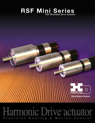
1. R S F Mi n i S e r i e s
RSF Brushless Servo Actuator
Total Motion Control
Harmonic Drive™actuator P r e c i s i o n G e a r i n g & M o t i o n C o n t r o l
2. 1. Applicable Models
This Specification applies to the RSF-B mini Series with parallel encoder and supply voltage DC 24V.
The sizes available are:
1) RSF-8B-XXX-F100-24B
2) RSF-11B-XXX-F100-24B
3) RSF-14B-XXX-F100-24B
2. Model Ordering Code
RSF-14 B-100-F 100-24 B
Model: AC Servo Actuator RSF mini Series
Size: 8, 11, 14
Design Version
Gear Ratio
30: 1/30
50: 1/50
100: 1/100
Encoder Specifications
F: Incremental Encoder
+Magnetic Pole Sensor
Encoder Resolution
100: 1000p/rev
Power Supply Voltage: DC24V
Phase Angle Specifications
B: 30°
Optional Specifications
No Sign: Without Connector
C: With Connector
3. Specification
Refer the manual of RSF-B mini standard type except the following specifications.
3-1 Actuator
Table 1 General specifications of RSF-8B/11B/14B
Item Environmental Conditions
Operate temperature 0~40 °C
Storage temperature -20~60 °C
Operate / Storage humidity 20~80%RH (No condensation)
Vibration resistance 25 m/s2 (Frequency: 10~400 Hz)
Impact resistance 300 m/s2
Sold & Serviced By:
ELECTROMATE
Toll Free Phone (877) SERVO98
Toll Free Fax (877) SERV099
www.electromate.com
sales@electromate.com
3. Model
Table 2 Ability Specifications
Item
RSF-8B RSF-11B RSF-14B
30 50 100 30 50 100 30 50 100
Power Suppy Voltage V DC24
Maximum Torque Nm 1.8 3.3 4.8 4.5 8.3 11 9.0 18 28
Maximum Speed r/min 200 120 60 200 120 60 200 120 60
Maximum Current A 3.8 3.9 2.9 14.4 15.8 9.4 14.4 17.2 12.3
Allowable Continuous
Nm 0.78 1.4 2.0 1.1 2.0 4.0 1.7 3.0 6.0
Torque
Allowable Continuous
Current
A 2.0 2.0 1.5 5.0 4.9 4.9 4.9 4.7 4.7
Allowable Continuous
Speed
r/min 100 60 30 100 60 30 100 60 30
Continuous torque at stall
Nm 0.95 1.7 3.5 1.7 3.0 5.7 2.5 4.5 9.0
Kgfcm 9.2 16 36 17 31 58 26 46 92
Torque Constant
Nm/A 0.62 1.1 2.1 0.40 0.66 1.5 0.76 1.3 2.6
Kgfcm/A 6.3 11 21 4.1 6.7 15 7.8 13 27
EMF Constant V(r/min) 0.07 0.11 0.22 0.04 0.07 0.15 0.08 0.13 0.28
Phase Resistance Ω (25°C) 0.93 0.19 0.26
Phase Inductance mH 0.45 0.10 0.19
Moment of Inertia4)
GD2/4
×10-2
k·gm2 0.06 0.16 0.65 0.18 0.49 2.0 0.41 1.1 4.5
J
×10-2
kgf·cm·s2 0.60 1.7 6.6 1.8 5.0 20 4.1 11 46
Allowable Radial Load N 196 245 392
kgf 20 25 40
Allowable Thrust Load
N 98 196 392
kgf 10 20 40
One-Way Positioning
Accuracy
arc/sec 180 150 150 150 120 120 150 120 120
Quad Encoder Resolution5) p/rev 120000 200000 400000 120000 200000 400000 120000 200000 400000
Mass kg 0.3 0.5 0.8
Servo Drive Combinations
DC24V
DCJ-055-09, DDP-090-09,
DEP-090-09
DDP-090-36, DEP-090-36
HA-680-4B-24 HA-680-6B-24
1) The table shows output values of the actuator.
2) All specifications are applicable for actuators mounted on an aluminum heat sink of size: 150 x 150 x 6(mm)
3) Values for saturated actuator temperature. Other values are for actuator temperature of 20°C.
4) The moment of inertia is the total value of the motor shaft and Harmonic Drive™ moment of inertia values
converted to the output side.
5) Quad encoder resolution is (motor shaft encoder resolution) x 4 x (gear ratio)
Sold & Serviced By:
ELECTROMATE
Toll Free Phone (877) SERVO98
Toll Free Fax (877) SERV099
www.electromate.com
sales@electromate.com
4. 3-2 Encoder Specifications
Table 3 Magnetic pole sensor (build in the motor)
Item Unit Specification
Signal U, U, V, V, W, W
Power supply voltage V DC +5 ±5%
Current consumption mA 250 max
Output circuit form Line driver
Table 4 Encoder
Item Unit Specification
Type Incremental, rectangular wave, 8-wires
Signal A, A, B, B, Z, Z
Resolution p/rev 1000
Power supply voltage V DC +5 ±5%
Current consumption mA 170 max
Output circuit form Line driver
Sold & Serviced By:
ELECTROMATE
Toll Free Phone (877) SERVO98
Toll Free Fax (877) SERV099
www.electromate.com
sales@electromate.com
5. HARMONIC ENGINEERING
INC
TOKYO JAPAN
DRIVE
SYSTEMS SYSTEMS
SPECIFICATION
• Singal waveform
● Signal waveform
T = Mean period
a,b,c,d = 0.25T ± 0.1T
e = 0.5T ± 0.1T
⊿t≦0.05T
α≦±1.5°(Mechanical angle)
U-N
Motor EMF waveform
Fig.1 A,B and Z signal and relationship with U-N motor EMF waveform with
R = 90゚±3゚(Mechanical angle)
Hn = 15゚±3゚(Mechanical angle)
δ≦±3°(Mechanical angle)
UUVV
WW
Fig.2 U,V and W signal and relationship with Motor's EMF with
CLASS SPEC NO.
B2I1870
a b c d
α
e
T
A
A
B
B
Z
Z
CW rotation facing the output shaft end
U-W(G) V-U(G) W-V(G)
Elec.Angle
Motor EMF waveform
δ
U
U
V
V
W
W
Magnetic pole sensor signal
CW rotation facing the output shaft end
Sold & Serviced By:
ELECTROMATE
Toll Free Phone (877) SERVO98
Toll Free Fax (877) SERV099
www.electromate.com
sales@electromate.com
REV DATE DESCRIPTION BY CHKD APPD SHEET NO. 5 OF 8
6. HARMONIC ENGINEERING
DRIVE
SYSTEMS SYSTEMS
SPECIFICATION
• Color code for leads
INC
TOKYO JAPAN
Color code for motor, encoder and magnetic pole sensor leads shown in Table 5
3-4 Color code for leads
Color code for motor, encoder and hall sensor leads shown in Table 5
Table 5 Color code
Motor leads Hall sensor leads Encoder leads
Color Signal Color Signal Color Signal
Red U Brown U Brown A
White V Blue U Blue A
Black W Red V Red B
Motor leads Hall sensor leads Encoder leads
Color Signal Color Signal Color Signal
Red U Brown Hu Brown A
White V Brown/Black Hu Blue A
Black W White Hv Red B
Green V Green B
Yellow W Yellow Z
Orange W Orange Z
White +5V (Vcc) White +5V (Vcc)
Black 0V (GND) Black 0V (GND)
White/Black Hv Green B
Blue Hw Yellow Z
Blue/Black Hw Orenge Z
Shield Floating
Table 5 Color code
Red +5V (Vcc) White +5V (Vcc)
Black 0V (GND) Black 0V (GND)
• Output circuit and example for receiving signal
Shield Floating
CLASS SPEC NO.
3-5 Output circuit and example for receiving signal
Actuator output circuit Input circuit of user’s device (Example)
Encoder Signal
VCC
A, B, Z
A -
, B -
, Z -
GND
R1≈120Ω
R1
U, V, W
VCC
U, V, W
Hu, Hv, Hw
GND
Hall Sensor Signal
Hu, Hv, Hw
Magnetic pole sensor Signal
Sold & Serviced By:
ELECTROMATE
Toll Free Phone (877) SERVO98
Toll Free Fax (877) SERV099
www.electromate.com
sales@electromate.com
7. HARMONIC ENGINEERING
INC
TOKYO JAPAN
DRIVE
SYSTEMS SYSTEMS
SPECIFICATION
4. External Dimensions
4.External dimensions of RSF-B mini actuators
RSF-8B-XXX-F100-24B
RSF-11B-XXX-F100-24B
CLASS SPEC NO.
B2I1870
Sold & Serviced By:
ELECTROMATE
Toll Free Phone (877) SERVO98
Toll Free Fax (877) SERV099
www.electromate.com
sales@electromate.com
REV DATE DESCRIPTION BY CHKD APPD SHEET NO. 7 OF 8
8. HARMONIC ENGINEERING
INC
TOKYO JAPAN
DRIVE
SYSTEMS SYSTEMS
SPECIFICATION
RSF-14B-XXX-F100-24B
CLASS SPEC NO.
B2I1870
Sold & Serviced By:
ELECTROMATE
Toll Free Phone (877) SERVO98
Toll Free Fax (877) SERV099
www.electromate.com
sales@electromate.com
REV DATE DESCRIPTION BY CHKD APPD SHEET NO. 8 OF 8