SlideShare a Scribd company logo
1 of 27
Download to read offline
AMO Automatisierung
M Oesstechnik ptik GmbH
LINEAR MEASURING SYSTEMS based on
the AMOSIN - Inductive Measuring Principle
®
! Inductive Encoders
comparable to Optical
Encoders in both
Accuracy and Resolution
(
! High Speeds up to
20 m/sec at 1 micron
resolution
!
!
!
±5 and ±3 micron /
meter accuracy and
down to 0.25 micron
resolution)
No Magnetic
Components
No Magnetic Field
Hysteresis or
Demagnetisation Risk
Protection Class IP 67
Fluid Submersible
Encoders
Unlimited Measuring
Lengths (>30 meters)
ELECTROMATE
Toll Free Phone (877) SERVO98
Toll Free Fax (877) SERV099
www.electromate.com
sales@electromate.com
Sold & Serviced By:
®
AMOSIN - general information
AMO's proven and original technology for length- and angle measurements uses techniques for scanning high precision graduations
consists of structures photo-lithographically etched onto steel. Based on this, inductive sensors with integrated evaluation electronics
(in ASIC) have been developed further, to create a new and powerful generation of measuring systems.
®
The AMOSIN length measuring systems are supplied in 2 principal versions: an open, non-contacting system, or as a guided,
encapsulated system.
®
Operating entirely on an inductive basis, the AMOSIN systems achieve high precisions of up to +/- 5 µm/m, but are nevertheless
very well able to resist environmental influences such as dust, humidity and so forth, also featuring an extremely high resistance to
shock and vibration.
The high precision is mainly due to the procedure used to manufacture the rigid steel measuring tape, and to the exceptionally high
quality sensor signal, with deviations in the sine wave down to < 0.1 % harmonic content, as a measure of the achievable interpolati-
on precision within the grating pitch.
As will be seen from the measuring principle described below, the measuring system does not include any magnetic parts (weither in
the measuring scale nor in the scanning head). As a result it is not at all sensitive to electromagnetic interference of any kind and has
no hysteresis, in contrast to magnetic measuring systems.
The systems output interface is either 1 Vpp sine/cosine signals, or RS-422 square wave signals, in real-time.
Not sensitive to soiling / IP 67
Not sensitive to interfering magnetic fields
High precision and resolution
General properties
High dynamic range
No functional hysteresis
Integrated reference mark,also distance coded
Machine tools
Direct drives
Metal plate working machines
SMT-pick and place machines
Measuring machines
Typical applications
Handling
Printing machines
Punching machines
Electronic production equipment
Hydraulic axes
Properties - the new generation
Analog output signals (1 Vpp) can also be delivered
with a reduced signal period of 40 µm
Digital output RS-422 / TTL with decimal resolution:
0.25 µm (1000 µm/4000) and 1µm (1000 µm/1000)
Introduction of the product group with a grating pitch of
3000 µm for high mounting tolerances.
The standard working temperature range has been
enlarged to 0-70 °C.
Dependency of the precision of the system on the
operating temperature has been significantly reduced.
Scanning head clearance (air gap between the
scanning head and the measuring tape) and its
tolerance have been increased.
The effects of mounting deviations within the
specified tolerances on the precision of the
system have been greatly reduced.
Miniaturisation of the evaluation electronics, which
has permitted integration of this circuitry into the
connector housing.
2
ELECTROMATE
Toll Free Phone (877) SERVO98
Toll Free Fax (877) SERV099
www.electromate.com
sales@electromate.com
Sold & Serviced By:
®
The AMOSIN measuring systems function on the
principle of a transformer with a moving reluctance
core. The mutual inductance of the primary and
secondary windings of a transformer changes in
accordancewiththerelativepositionofthecore.
The AMOSIN system consists primarily of a planar
coil and a measuring scale (Fig.1). The coil
structure, with a number of winding elements
(individual main elements with primary and
secondary SIN/COS coils) aligned in the direction
of measurement, is implemented on a substrate
using micro-multi-layer technology. The measu-
ring scale is a stainless-steel tape onto which a
highly precise graduation (e.g. l = 1000 µm) of
variable reluctance has been etched using photo-
lithographictechniques.
The relative movement in the direction of measurement between the sensor structure (in the scanning head) and the measuring scale
periodically changes the mutual inductance of the individual coils, generating two sinusoidal signals with a 90° phase difference (SIN
and COS). The extremely accurate signal, and its immunity to environmental influences, has the effect that, after conditioning of the
signal in the evaluation electronics (Fig. 2), deviations of no more than 0.1% from the ideal sinusoidal form (harmonic content)
remains. This allows high interpolation factors (further levels of sub-division) to be carried out in the course of signal digitisation. This
can either be done in the measuring system itself, or in the subsequent electronics (CNC etc.).
An important feature of the
principle of operation is that using
®
the AMOSIN procedure does not
give rise to any measurement
hysteresis (mach-ine backlash
error). In contrast to magnetic
systems, the high-frequency
alternating field sup-presses any
hysteresis in the material.
The evaluation electronics con-
ditions the sensor signals and
interpolates them continuously,
without using strobe times,
exploiting a novel circuit principle.
It then supplies the measurement
information at the output through
differential interfaces and line
drivers, either as a sinusoidal
signal or as a square wave signal.
(see the signal diagram on Page 23)
In addition to the periodic signals
(A, B and their inverted) a
reference signal is output for the
determination of absolute posi-
tion. This signal is generated from
individual marks integrated into the
measuring scale, and does not
require any additional parts. (see
the description of the reference
signal on Page 23)
3
®
AMOSIN - the measuring principle
AMOSIN
MEASURING SYSTEM
(Fig. 2)
AMOSIN - MEASURING PRINCIPLE
(Fig. 1)
Primary windings
Secondary windings
Micro-coil
structure
Sensor substrate
Measuring scale
SIN COS SIN COS
EEPROM
configuration
data
Power supply
unit
ASIC signal
conditioning
+ evaluation
Compensation
signals
Electronic evaluation
stage
Sensor unit
Measuring scale
Analog
output
~ 1 Vpp
Encoder
output
RS 422
ELECTROMATE
Toll Free Phone (877) SERVO98
Toll Free Fax (877) SERV099
www.electromate.com
sales@electromate.com
Sold & Serviced By:
Measuring accuracy
The total error of a measuring system is caused by the following measuring inaccuracies:
1. Precision of the graduation - determined by the precision of the measuring scale
2. Precision within one grating pitch - primarily determined by the quality of the sensor signal and its evaluation electronics.
The following should also be considered for the measuring systems with a 1 Vpp output interface:
3. Precision of the analog/digital conversion at the input stage of the subsequent electronics (in the controller)
4. Noise coupled into the output signals as it is transferred from the scanning head to the subsequent electronics
A detailed description of these aspects follows:
1. Scale accuracy
Every measuring scale is measured on a linear test bench, and a test certificate, quoting the precision class in accordance with
specification, is completed. Optionally a measuring diagram (measured under ideal mounting conditions) can be supplied, as
follows.
2. Precision within one grating pitch
®
These errors are extremely small on AMOSIN systems, and are in the region of 0.1 % of the grating pitch (corresponding 1 µm
for a grating pitch of 1000 µm). This maximum precision is not just relevant to the ideal set-up, but is also retained when the
mounting tolerances and working temperature range are exploited. Every scanning head is adjusted and tested on the basis of
these tight criteria of quality.
In order to suppress the errors discussed above under points "3" and "4", a new output interface has been implemented in the new
®
generation of AMOSIN systems, in which the sine, cosine and reference signals, for the 1 Vpp output interface, are divided and over
line drivers (see signal diagram on Page 23).
The dividing of the grating pitch (D) generates a signal corresponding to a pitch of 40 µm in real-time, if a measuring scale with a
grating pitch of 1000 µm is used.
The effect of any possible deviation in the evaluation (A/D conversion) in the subsequent electronics (controller etc.), is reduced in this
signal interface by exactly the dividing factor (D) that is applied. In addition, this reduced sinusoidal signal period leads to finer
quantisation in the subsequent electronics, which is of particularly great importance to demanding high dynamic and stiff drive
applications.
Additionally, the signal division reduces the effect of noise coupling on the signal transfer line, in proportion to the dividing factor "D";
in other words, an improved signal/noise ratio is achieved.
®
The metrological principle on which the AMOSIN systems operate means that they are entirely free from hysteresis.
4
ELECTROMATE
Toll Free Phone (877) SERVO98
Toll Free Fax (877) SERV099
www.electromate.com
sales@electromate.com
Sold & Serviced By:
5
So that it can be dismounteded, the stainless-steel
measuring scale is fixed by means of alignment pins and
clamps in the guided, encapsulated measuring systems
from the LMI-310 series.
In the LMI-200 series, the measuring tape is permanently
bonded to the guide rail.
In the open, non-contacting systems, a double-sided
adhesive foil is applied for direct sticking on the machine
bed.
In all of these versions, the scanning still takes place
without contact, and is therefore not subject to wear.
Measuring system configuration
Measuring rail
Mounting pad
Mounting element
Measuring slider
Cover tape
Measuring scale
1. Grating pitch:
2. Type of scanning:
3. Measuring scale:
4. Scanning head:
- l = 1000 µm for maximum precision
- l = 3000 µm for larger mounting tolerances
- open - without contact
- guided - encapsulated
- measuring tape
- measuring rail
- miniature version with electronics in connector
- fully integrated electronics
The main selection criteria are illustrated in the following table.
Measuring scale
Adhesive tapeCover tape
Carrier tape
Mounting bracket
(on both ends)
Mounting element
Measuring slider
Cover tape
Measuring scale
with carrier tape
Adjusting screw
Mesuring rail
Mounting hole for
the measuring rail
Scanning head
Measuring slider LMK-310 with
integrated electronics
Measuring rail LMF-310 in single
or multiple sections for long
measuring axis
The scale can be adjusted to
compensate axis accuracy
LMI-310
Measuring slider
LMK-200 - miniature with
connector electronics
LMK-210 - with integrated
electronics(not figured)
Miniature measuring rail LMF-200
with welded scale
LMI-200
Measuring head
LMK-100 - miniature with
connector electronics
LMK-110 - with integrated
electronics(not figured)
Measuring scale for direct sticking
on the machine base
LMI-100
ELECTROMATE
Toll Free Phone (877) SERVO98
Toll Free Fax (877) SERV099
www.electromate.com
sales@electromate.com
Sold & Serviced By:
6
l = 1000 µm l = 3000 µm
LMI-100
LMI-110
Selection table:
Grating pitch
LMI-130
LMI-200
LMI-210
LMI-310
LMB-100 Page 07
LMK-100 Page 07
LMB-110 Page 09
LMK-110 Page 10
-
-
LMF-200 Page 14
LMK-200 Page 15
LMF-200 Page 17
LMK-210 Page 17
LMF-310 Page 19
LMK-310 Page 21
-
-
-
-
LMB-130 Page 12
LMK-130 Page 12
-
-
-
-
-
-
Measuring scale
Scanning head miniature
Measuring scale
Scanning head
Measuring scale
Scanning head
Measuring rail
Measuring slider miniature
Measuring rail
Measuring slider
Measuring rail
Measuring slider
Withoutcontact
Open
Guided
Encapsulated
Measuring systems for open, non-contact scanning with grating pitch of l=1000µm
Open measuring system
Miniature design with connector electronics
No wear
Ideal for applications with high dynamic range
High precision
Suited for long axis
Devided sinus output of 40 µm
LMI-100
Connector dimensions see page 25
Main features:
ELECTROMATE
Toll Free Phone (877) SERVO98
Toll Free Fax (877) SERV099
www.electromate.com
sales@electromate.com
Sold & Serviced By:
Technical Data:
Grating pitch:
Linearity error:
Coefficient of expansion:
Measuring length:
Mechanical execution:
Reference position:
1000 µm
LMB-100.0 =±20 µm
LMB-100.1 =±10 µm
LMB-100.2 =± 5 µm
~11ppm
Up to a maximum of 30 m
Stainless-steel measuring tape, with adhesive layer for mounting
Normally in the middle, any position and number, or distance-encoded (see description on page 24)
0
LMB-100 measuring tape
Tape length in mm
LMB-100. - - RI position (like above sketch)
0 ... none
1 ... 50 mm from the left
2 ... central
3 ... 50 mm from the right
4 ... 100 mm from the left
5 ... 100 mm from the right
6 ... 50 mm from both sides
7 ... 100 mm from both sides
8 ... all 100 mm
9 ... Special RI position(s) (requires a special no. Sxx)
K1 … distance-coded (basic spacing 40 mm)
K2 … distance-coded (basic spacing 80 mm)
K3 … distance-coded (basic spacing 120 mm)
Ordering code:
LMK-10 scanning head
Operating temperature:
Storage temperature:
Protection class:
Vibration:
Shock:
Power supply:
Cable:
Output signals:
Optional:
Max. Speed:
0° to 70° C (higher temperatures by request)
-20°C to 85°C
Scanning head: IP 67
Connector electronics / versions with CONNEI connector: IP 67
Connector electronics / version with 15-pin Sub-D connector: IP 54
2
<400 m/s for 55 - 2000 Hz
2
<2000 m/s for 6 ms
See the following table (sensor lines available, see page 26)
PUR jacket, high flexibility, dmr. 5.3 mm, 5(2x0.05) + 1 (2x0.14) mm²
(Bending radius: 10 x d = 50mm continuous bending; 5 x d = 25mm single bend)
! LMK-101. analog output 1 Vpp to 120 W terminating resistor·
with sinus output of 1000 µm or 40 µm
! LMK-102. TTL output - resolution as in the following table
Limit switch function (see description on page 22)
LED on the connector housing as an assembly aid (by request)
W
LMK-101.0
LMK-101.3
1 Vpp/1000 µm
1 Vpp/40 µm
Type Output signal/resolution
10 m/s
10 m/s
Speed
LMK-102.0
LMK-102.1
LMK-102.4
LMK-102.5
TTL/10 µm*
TTL/5 µm*
TTL/1 µm*
TTL/0.25 µm*
10 m/s
2.5 m/s
20 m/s
7
Linearity error
0 ... ±20 µm
1 ... ±10 µm
2 ... ± 5 µm0
*) after 4x edge evaluation
(see diagram on page 23)
260 mA
260 mA
Power Supply 5V ±5%
300 mA
ELECTROMATE
Toll Free Phone (877) SERVO98
Toll Free Fax (877) SERV099
www.electromate.com
sales@electromate.com
Sold & Serviced By:
LMK-101. --
Ordering code:
- Connector / version
5 ... 15-pin Sub-D plug
6 ... 12-pin CONNEI coupling (male)
screwed cable gland at the input
6A ... 12-pin input CONNEI coupling (female)
output 12-pin CONNEI coupling (male)
0
0
06 ...
6A ...
Cable length (in whole metres)
1 ... 1m (preferred length)
2 ... 2m
3 ... 3m (preferred length)
X ... special length (may require a special no. Sxx)
Signal period
0 ... 1000 m
3 ... 40 m
µ
µ
Limit switch
0 ... none
1 ... with
L ... reference pulse selectable
Limit switch
0 ... none
1 ... with
L ... reference pulse selectable
LMK-102. -- - Connector / version
5 ... 15-pin Sub-D plug
6 ... 12-pin CONNEI coupling (male)
screwed cable gland at the input
6A ... 12-pin input CONNEI coupling (female)
output 12-pin CONNEI coupling (male)
0
0
06 ...
6A ...
Cable length (in whole metres)
1 ... 1m (preferred length)
2 ... 2m
3 ... 3m (preferred length)
X ... special length (may require a special no. Sxx)
Resolution
after 4x edge
evaluation
0 ... 10 m
1 ... 5 m
4 ... 1 m
5 ... 0.25 m
µ
µ
µ
µ
0
0
Scanning head with 1 Vpp output signal – LMK-101
Scanning head with TTL (RS422) output signal – LMK-102
Dimensions:
8
ELECTROMATE
Toll Free Phone (877) SERVO98
Toll Free Fax (877) SERV099
www.electromate.com
sales@electromate.com
Sold & Serviced By:
Grating pitch:
Linearity error:
Coefficient of expansion:
Measuring length:
Mechanical execution:
Reference position:
1 mm
LMB-110.0 =±20 µm
LMB-110.1 =±10 µm
LMB-110.2 =± 5 µm
~11ppm
Up to a maximum of 30 m
Stainless-steel measuring tape, with adhesive layer for mounting
Normally in the middle, any position and number, or distance-coded (see description on page 24)
0
LMB-110 measuring tape
Tape length in mm
LMB-110. - - RI position (like above sketch)
0 ... none
1 ... 50 mm from the left
2 ... central
3 ... 50 mm from the right
4 ... 100 mm from the left
5 ... 100 mm from the right
6 ... 50 mm from both sides
7 ... 100 mm from both sides
8 ... all 100 mm
9 ... Special RI position(s) (requires a special no. Sxx)
K1 … distance-coded (basic spacing 40 mm)
K2 … distance-coded (basic spacing 80 mm)
K3 … distance-coded (basic spacing 120 mm)
Ordering code:
Linearity error
0 ... ±20 µm
1 ... ±10 µm
2 ... ± 5 µm0
9
Open measuring system
Suited for long axis
Devided sinus output of 40 µm
Integrated electronics
No wear
Ideal for applications with
high dynamic range
High precision
Technical Data:
Main features:
LMI-110
Also available in - design for explosion sensitive
environments (see datasheet or www.amo.at)
ELECTROMATE
Toll Free Phone (877) SERVO98
Toll Free Fax (877) SERV099
www.electromate.com
sales@electromate.com
Sold & Serviced By:
Abtastkopf LMK-11
0°C to 70°C (higher temperatures by request)
-20°C to 85°C
Scanning head: IP 67
2
<200 m/s for 55 - 2000 Hz
2
<1000 m/s for 6 ms
See the following table (sensor lines available, see page 26)
PUR jacket, high flexibility, dmr. 5.3 mm, 5(2x0.05) + 1 (2x0.14) mm²
(Bending radius: 10 x d = 50mm continuous bending; 5 x d = 25mm single bend)
Maximum length 9m, up to 50m with extension cable (see page 26)
! LMK-111. analog output 1 Vpp to 120 W terminating resistor·
with sinus output of 1000 µm or 40 µm
! LMK-112. TTL output - resolution as in the following table
Limit switch function (see description on page 22)
W
*) after 4x edge evaluation
LMK-111. --
Ordering code:
-
Signal period
0 ... 1000 m
3 ... 40 m
µ
µ
Scanning head with 1 Vpp output signal - LMK-111 Connector / version
0 ... none
1 ... 12-pin DIN connector
3 ... 9-pin Sub-D plug
4 ... 12-pin CONNEI plug (male)
5 ... 15-pin Sub-D plug
6 ... 12-pin CONNEI coupling (male)
9 ... special connector or special pin-out
(requires special no. Sxx)9 ...
Cable length (in whole metres)
1 ... 1m (preferred length)
3 ... 3m (preferred length)
9 ... 9 m
X ... special length (may require a special no. Sxx)
LMK-112. -- -
Scanning head with TTL (RS422) output signal - LMK-112 Connector / version
0 ... none
1 ... 12-pin DIN connector
3 ... 9-pin Sub-D plug
4 ... 12-pin CONNEI plug (male)
5 ... 15-pin Sub-D plug
6 ... 12-pin CONNEI coupling (male)
9 ... special connector or special pin-out
(requires special no. Sxx)9 ...
Cable length (in whole metres)
1 ... 1m (preferred length)
3 ... 3m (preferred length)
9 ... 9 m
X ... special length (may require a special no. Sxx)
Resolution
after 4x edge
evaluation
0 ... 10 m
1 ... 5 m
4 ... 1 m
5 ... 0.25 m
µ
µ
µ
µ
0
0
10
Operating temperature:
Storage temperature:
Protection class:
Vibration:
Shock:
Power supply:
Cable:
Output signals:
Optional:
Max. Speed:
(see diagram on page 23)
Limit switch
0 ... none
1 ... with
L ... reference pulse selectable
Limit switch
0 ... none
1 ... with
L ... reference pulse selectable
LMK-111.0
LMK-111.3
1 Vpp/1000 µm
1 Vpp/40 µm
Type Output signal/resolution
10 m/s
10 m/s
Speed
LMK-112.0
LMK-112.1
LMK-112.4
LMK-112.5
TTL/10 µm*
TTL/5 µm*
TTL/1 µm*
TTL/0.25 µm*
10 m/s
2.5 m/s
20 m/s
200 mA
Power Supply 5V ±5%
260 mA
*
*
The - option is designated - EX2*
ELECTROMATE
Toll Free Phone (877) SERVO98
Toll Free Fax (877) SERV099
www.electromate.com
sales@electromate.com
Sold & Serviced By:
Dimensions:
Measuring systems for open, non-contact scanning with grating pitch of l=3000µm
Open measuring system
Integrated electronics
No wear
Wide mounting tolerances
LMI-130
11
Main features:
Also available in - design for explosion sensitive
environments (see datasheet or www.amo.at)
ELECTROMATE
Toll Free Phone (877) SERVO98
Toll Free Fax (877) SERV099
www.electromate.com
sales@electromate.com
Sold & Serviced By:
Technical Data:
Grating pitch:
Linearity error:
Coefficient of expansion:
Measuring length:
Mechanical execution:
Reference position:
3 mm
LMB-130.0 =±20 µm
~11ppm
Up to a maximum of 30 m
Stainless-steel measuring tape,
with adhesive layer for mounting
Normally in the middle, any position is possible
LMB-130 measuring tape
Tape length in mm
LMB-130. - -
RI position (like above sketch)
0 ... none
1 ... 50 mm from the left
2 ... central
3 ... 50 mm from the right
4 ... 100 mm from the left
5 ... 100 mm from the right
6 ... 30 mm from both sides
7 ... 60 mm from both sides
8 ... all 90 mm
9 ... Special RI position(s) (requires a special no. Sxx)
Ordering code:
Abtastkopf LMK-13
0° to 70° C (higher temperatures by request)
-20°C to 85°C
Scanning head: IP 67
2
<200 m/s for 55 - 2000 Hz
2
<1000 m/s for 6 ms
See the following table (sensor lines available, see page 26)
PUR jacket, high flexibility, dmr. 5.3 mm, 5(2x0.05) + 1 (2x0.14) mm²
(Bending radius: 10 x d = 50mm continuous bending; 5 x d = 25mm single bend)
Maximum length 9m, up to 50m with extension cable (see page 26)
! LMK-131. analog output 1 Vpp to 120 W terminating resistor
! LMK-132. TTL output - resolution as in the following table
Limit switch function (see description on page 22)
W
LMK-131.0
LMK-131.3
1 Vpp/3000 µm
1 Vpp/120 µm
Type Output signal/resolution
30 m/s
30 m/s
Speed
LMK-132.0
LMK-132.1
LMK-132.4
LMK-132.5
TTL/30 µm*
TTL/15 µm*
TTL/3 µm*
TTL/0.75 µm*
30 m/s
7.5 m/s
60 m/s
Linearity error
0 ... ±20 µm
*) after 4x edge evaluation
12
Operating temperature:
Storage temperature:
Protection class:
Vibration:
Shock:
Power supply:
Cable:
Output signals:
Optional:
Max. Speed:
(see diagram on page 23)
200 mA
Power Supply 5V ±5%
260 mA
ELECTROMATE
Toll Free Phone (877) SERVO98
Toll Free Fax (877) SERV099
www.electromate.com
sales@electromate.com
Sold & Serviced By:
Limit switch
0 ... none
1 ... with
LMK-131. --
Ordering code:
-
Signal period
0 ... 3000 m
3 ... 120 m
µ
µ
Scanning head with 1 Vpp output signal - LMK-131 Connector / version
0 ... none
1 ... 12-pin DIN connector
3 ... 9-pin Sub-D plug
4 ... 12-pin CONNEI plug (male)
5 ... 15-pin Sub-D plug
6 ... 12-pin CONNEI coupling (male)
9 ... special connector or special pin-out
(requires special no. Sxx)9 ...
Cable length (in whole metres)
1 ... 1m (preferred length)
3 ... 3m (preferred length)
9 ... 9 m
X ... special length (may require a special no. Sxx)
LMK-132. -- -
Scanning head with TTL (RS422) output signal - LMK-132 Connector / version
0 ... none
1 ... 12-pin DIN connector
3 ... 9-pin Sub-D plug
4 ... 12-pin CONNEI plug (male)
5 ... 15-pin Sub-D plug
6 ... 12-pin CONNEI coupling (male)
9 ... special connector or special pin-out
(requires special no. Sxx)9 ...
Cable length (in whole metres)
1 ... 1m (preferred length)
3 ... 3m (preferred length)
9 ... 9 m
X ... special length (may require a special no. Sxx)
Resolution
after 4x edge
evaluation
0 ... 30 m
1 ... 15 m
4 ... 3 m
5 ... 0.75 m
µ
µ
µ
µ
0
Dimensions:
13
Limit switch
0 ... none
1 ... with
L ... reference pulse selectable
The - option is designated - EX2*
*
*
ELECTROMATE
Toll Free Phone (877) SERVO98
Toll Free Fax (877) SERV099
www.electromate.com
sales@electromate.com
Sold & Serviced By:
Measuring systems for guided - encapsulated scanning with grating pitch of l=1000µm
Miniature measuring rail
Miniature measuring slider with
connector electronics
Stainless-steel version
Ideal for tough environment
High precision
Large mounting tolerances of±1 mm
over flexure element
LMI-200
Technical Data:
Grating pitch:
Accuracy:
Coefficient of expansion:
Measuring length:
Reference position:
1 mm
LMF-200.0 =±20 µm
LMF-200.1 =±10 µm
LMF-200.2 =± 5 µm
~11ppm
120 / 170 / 220 / 270 / 320 / 420 / 520 / 620 / 720 / 820 / 920 / 1020 mm
Longer lengths by request
Standard in the middle, any position and number, or distance-coded (see description on page 24)
0
LMF-200 measuring rail
Measuring length in mm
Standard: 120 / 170 / 220 /
270 / 320 / 420 / 520 / 620 /
720 / 820 / 920 / 1020
Longer lengths by request
LMF-200. - - RI position (like above sketch)
0 ... none
1 ... 50 mm from the left
2 ... central
3 ... 50 mm from the right
4 ... 100 mm from the left
5 ... 100 mm from the right
6 ... 50 mm from both sides
7 ... 100 mm from both sides
8 ... all 100 mm
9 ... Special RI position(s) (requires a special no. Sxx)
K1 … distance-coded (basic spacing 40 mm)
K2 … distance-coded (basic spacing 80 mm)
K3 … distance-coded (basic spacing 120 mm)
Ordering code:
Accuracy
0 ... ±20 µm
1 ... ±10 µm
2 ... ± 5 µm0
14
Connector dimensions
see page 25
Main features:
ELECTROMATE
Toll Free Phone (877) SERVO98
Toll Free Fax (877) SERV099
www.electromate.com
sales@electromate.com
Sold & Serviced By:
LMK-20 - measuring slider
0° to 70° C (higher temperatures by request)
-20°C to 85°C
Scanning head: IP 67
Connector electronics / versions with CONNEI connector: IP 67
Connector electronics / version with 15-pin Sub-D connector: IP 54
See the following table (sensor lines available, see page 26)
PUR jacket, high flexibility, dmr. 5.3 mm, 5(2x0.05) + 1 (2x0.14) mm²
(Bending radius: 10 x d = 50mm continuous bending; 5 x d = 25mm single bend)
! LMK-201. analog output 1 Vpp to 120 W terminating resistor·
with sinus output of 1000 µm or 40 µm
! LMK-202. TTL output - resolution as in the following table
Limit switch function (see description on page 22)
LED on the connector housing as an assembly aid (by request)
W
LMK-201.0
LMK-201.3
1 Vpp/1000 µm
1 Vpp/40 µm
Type Output signal/resolution
1)
3 m/s
1)
3 m/s
Speed
LMK-202.0
LMK-202.1
LMK-202.4
LMK-202.5
2)
TTL/10 µm
2)
TTL/5 µm
2)
TTL/1 µm
2)
TTL/0.25 µm
1)
3 m/s
2.5 m/s
3 m/s 1)
1) 2)
limited by the mechanics after 4x edge evaluation
LMK-201. --
Ordering code:
- Connector / version
5 ... 15-pin Sub-D plug
6 ... 12-pin CONNEI coupling (male)
screwed cable gland at the input
6A ... 12-pin input CONNEI coupling (female)
output 12-pin CONNEI coupling (male)
0
0
06 ...
6A ...
Cable length (in whole metres)
1 ... 1m (preferred length)
2 ... 2m
3 ... 3m (preferred length)
X ... special length (may require a special no. Sxx)
Signal period
0 ... 1000 m
3 ... 40 m
µ
µ
LMK-202. -- - Connector / version
5 ... 15-pin Sub-D plug
6 ... 12-pin CONNEI coupling (male)
screwed cable gland at the input
6A ... 12-pin input CONNEI coupling (female)
output 12-pin CONNEI coupling (male)
0
0
06 ...
6A ...
Cable length (in whole metres)
1 ... 1m (preferred length)
2 ... 2m
3 ... 3m (preferred length)
X ... special length (may require a special no. Sxx)
Resolution
after 4x edge
evaluation
0 ... 10 m
1 ... 5 m
4 ... 1 m
5 ... 0.25 m
µ
µ
µ
µ
0
0
Measuring slider with 1 Vpp output signal evaluation - LMK-201
Measuring slider with TTL (RS422) output signal - LMK-202
15
Operating temperature:
Storage temperature:
Protection class:
Power supply:
Cable:
Output signals:
Optional:
Max. Speed:
(see diagram on page 23)
Limit switch
0 ... none
1 ... with
L ... reference pulse selectable
Limit switch
0 ... none
1 ... with
L ... reference pulse selectable
260 mA
Power Supply 5V ±5%
300 mA
ELECTROMATE
Toll Free Phone (877) SERVO98
Toll Free Fax (877) SERV099
www.electromate.com
sales@electromate.com
Sold & Serviced By:
16
LMI-210
Miniature measuring rail
Measuring slider with integrated electronics
Stainless-steel version
Ideal for rough environment
High precision
Dimensions:
Main features:
ELECTROMATE
Toll Free Phone (877) SERVO98
Toll Free Fax (877) SERV099
www.electromate.com
sales@electromate.com
Sold & Serviced By:
Technical Data:
Grating pitch:
Accuracy:
Coefficient of expansion:
Measuring length:
Reference position:
1 mm
LMF-200.0 =±20 µm
LMF-200.1 =±10 µm
LMF-200.2 =± 5 µm
~11ppm
120 / 170 / 220 / 270 / 320 / 420 / 520 / 620 / 720 / 820 / 920 / 1020 mm
Longer lengths by request
Normally in the middle, any position and number, or distance-coded (see description on page 24)
0
LMF-200 measuring rail
Measuring length in mm
Standard: 120 / 170 / 220 /
270 / 320 / 420 / 520 / 620 /
720 / 820 / 920 / 1020
Longer lengths by request
LMF-200. - - RI position (like above sketch)
0 ... none
1 ... 50 mm from the left
2 ... central
3 ... 50 mm from the right
4 ... 100 mm from the left
5 ... 100 mm from the right
6 ... 50 mm from both sides
7 ... 100 mm from both sides
8 ... all 100 mm
9 ... Special RI position(s) (requires a special no. Sxx)
K1 … distance-coded (basic spacing 40 mm)
K2 … distance-coded (basic spacing 80 mm)
K3 … distance-coded (basic spacing 120 mm)
Ordering code:
Accuracy
0 ... ±20 µm
1 ... ±10 µm
2 ... ± 5 µm0
LMK-21 - measuring slider
0°C to 70°C (higher temperatures by request)
-20°C to 85°C
Scanning head: IP 67
See the following table (sensor lines available, see page 26)
PUR jacket, high flexibility, dmr. 5.3 mm, 5(2x0.05) + 1 (2x0.14) mm²
(Bending radius: 10 x d = 50mm continuous bending; 5 x d = 25mm single bend)
! LMK-111. analog output 1 Vpp to 120 W terminating resistor·
with sinus output of 1000 µm or 40 µm
! LMK-112. TTL output - resolution as in the following table
Limit switch function
W
LMK-211.0
LMK-211.3
1 Vpp/1000 µm
1 Vpp/40 µm
Type Output signal/resolution
1)
3 m/s
1)
3 m/s
Speed
LMK-212.0
LMK-212.1
LMK-212.4
LMK-212.5
2)
TTL/10 µm
2)
TTL/5 µm
2)
TTL/1 µm
2)
TTL/0.25 µm
1)
3 m/s
2.5 m/s
3 m/s 1)
1) 2)
limited by the mechanics after 4x edge evaluation
17
Operating temperature:
Storage temperature:
Protection class:
Power supply:
Cable:
Output signals:
Optional:
Max. Speed:
(see diagram on page 23)
200 mA
Power Supply 5V ±5%
260 mA
ELECTROMATE
Toll Free Phone (877) SERVO98
Toll Free Fax (877) SERV099
www.electromate.com
sales@electromate.com
Sold & Serviced By:
LMK-211. -- -
Measuring slider with 1 Vpp output signal - LMK-211 Connector / version
0 ... none
1 ... 12-pin DIN connector
3 ... 9-pin Sub-D plug
4 ... 12-pin CONNEI plug (male)
5 ... 15-pin Sub-D plug
6 ... 12-pin CONNEI coupling (male)
9 ... special connector or special pin-out
(requires special no. Sxx)9 ...
Cable length (in whole metres)
1 ... 1m (preferred length)
3 ... 3m (preferred length)
9 ... 9 m
X ... special length (may require a special no. Sxx)
LMK-212. -- -
Measuring slider with TTL (RS422) output signal - LMK-212 Connector / version
0 ... none
1 ... 12-pin DIN connector
3 ... 9-pin Sub-D plug
4 ... 12-pin CONNEI plug (male)
5 ... 15-pin Sub-D plug
6 ... 12-pin CONNEI coupling (male)
9 ... special connector or special pin-out
(requires special no. Sxx)9 ...
Cable length (in whole metres)
1 ... 1m (preferred length)
3 ... 3m (preferred length)
9 ... 9 m
X ... special length (may require a special no. Sxx)
Resolution
after 4x edge
evaluation
0 ... 10 m
1 ... 5 m
4 ... 1 m
5 ... 0.25 m
µ
µ
µ
µ
0
0
18
Dimensions:
Ordering code:
Limit switch
0 ... none
1 ... with
L ... reference pulse selectable
Limit switch
0 ... none
1 ... with
L ... reference pulse selectable
Signal period
0 ... 1000 m
3 ... 40 m
µ
µ
ELECTROMATE
Toll Free Phone (877) SERVO98
Toll Free Fax (877) SERV099
www.electromate.com
sales@electromate.com
Sold & Serviced By:
Measuring systems for guided - encapsulated scanning with grating pitch l=1000µm
Robust mechanical design
Integrated electronics
Ideal for tough environment
and long measuring lengths
(single or multiple sections)
High precision
Easy mounting and large ounting
tolerances of±1 mm over
flexure element
LMI-310
Technical Data:
Grating pitch:
Accuracy:
Coefficient of expansion:
Measuring length:
Reference position:
1 mm
LMF-310.0 =±20 µm
LMF-310.1 =±10 µm
LMF-310.2 =± 5 µm
~11ppm
a) One-piece measuring rail:
70, 130, 190, ... ML=((n-1) x 60) - 50 [mm] ML max. 3790 mm
n ... number of fastening holes n ³ 3
b) Multi-piece measuring rail:
Any desired ML (in steps of 60 mm) but with the condition: ML=((n-1) x 60) - 50 [mm], n ³ 3
Normally in the middle, any position and number, or distance-coded (see description on page 24)
0
LMF-310 measuring rail
19
Dimensions of measuring rail LMF-200
Main features:
ELECTROMATE
Toll Free Phone (877) SERVO98
Toll Free Fax (877) SERV099
www.electromate.com
sales@electromate.com
Sold & Serviced By:
Measuring length (ML) in mm
L max. 3790 mm for
one-piece version
Any ML for
multi-piece version
LMF-310. - - RI position (like sketch Page 19)
0 ... none
1 ... 50 mm from the left
2 ... central
3 ... 50 mm from the right
4 ... 100 mm from the left
5 ... 100 mm from the right
6 ... 50 mm from both sides
7 ... 100 mm from both sides
8 ... all 100 mm
9 ... Special RI position(s) (requires a special no. Sxx)
K1 … distance-coded (basic spacing 40 mm)
K2 … distance-coded (basic spacing 80 mm)
K3 … distance-coded (basic spacing 120 mm)
Ordering code:
Accuracy
0 ... ±20 µm
1 ... ±10 µm
2 ... ± 5 µm0
Surface
0 ... without
1 ... with Cr coating
Dimensions:
20
ELECTROMATE
Toll Free Phone (877) SERVO98
Toll Free Fax (877) SERV099
www.electromate.com
sales@electromate.com
Sold & Serviced By:
LMK-31 - measuring slider
Operating temperature:
Storage temperature:
Protection class:
Power supply:
Cable:
Output signals:
Optional:
Max. Speed:
0°C to 70°C (higher temperatures by request)
-20°C to 85°C
Scanning head: IP 67
See the following table (sensor lines available, see page 26)
PUR jacket, high flexibility, dmr. 5.3 mm, 5(2x0.05) + 1 (2x0.14) mm²
(Bending radius: 10 x d = 50mm continuous bending; 5 x d = 25mm single bend)
Maximum length 9m, up to 50m with extension cable (see page 26)
! LMK-311. analog output 1 Vpp to 120 W terminating resistor
with sinus output of 1000 µm or 40 µm
! LMK-312. TTL output - resolution as in the following table
Limit switch function (see description on page 22)
W
1) 2)
limited by the mechanics after 4x edge evaluation
Technical Data:
21
(see diagram on page 23)
LMK-311.0
LMK-311.3
1 Vpp/1000 µm
1 Vpp/40 µm
Type Output signal/resolution
1)
3 m/s
1)
3 m/s
Speed
LMK-312.0
LMK-312.1
LMK-312.4
LMK-312.5
2)
TTL/10 µm
2)
TTL/5 µm
2)
TTL/1 µm
2)
TTL/0.25 µm
1)
3 m/s
2.5 m/s
3 m/s 1)
200 mA
Power Supply 5V ±5%
260 mA
ELECTROMATE
Toll Free Phone (877) SERVO98
Toll Free Fax (877) SERV099
www.electromate.com
sales@electromate.com
Sold & Serviced By:
Connector / version
0 ... none
1 ... 12-pin DIN connector
3 ... 9-pin Sub-D plug
4 ... 12-pin CONNEI plug (male)
5 ... 15-pin Sub-D plug
6 ... 12-pin CONNEI coupling (male)
9 ... special connector or special pin-out
(requires special no. Sxx)9 ...
Cable length (in whole metres)
1 ... 1m (preferred length)
3 ... 3m (preferred length)
9 ... 9 m
X ... special length (may require a special no. Sxx)
Signal period
0 ... 1000 m
3 ... 40 m
µ
µ
Surface
0 ... without
1 ... with Cr coating
LMK-311. --
Measuring slider with 1 Vpp output signal - LMK-311
-
-- -
Measuring slider with TTL (RS422) output signal - LMK-312
Surface
0 ... without
1 ... with Cr coating
Resolution
after 4x edge
evaluation
0 ... 10 m
1 ... 5 m
4 ... 1 m
5 ... 0.25 m
µ
µ
µ
µ
0
0
LMK-312.
Limit switch function
The limit switch sensor is located in the centre of the scanning head (see mounting drawing).
The limit switch output is implemented as an open-collector circuit (see circuit diagram).
Limit switch function output circuit:
22
Connector / version
0 ... none
1 ... 12-pin DIN connector
3 ... 9-pin Sub-D plug
4 ... 12-pin CONNEI plug (male)
5 ... 15-pin Sub-D plug
6 ... 12-pin CONNEI coupling (male)
9 ... special connector or special pin-out
(requires special no. Sxx)9 ...
Cable length (in whole metres)
1 ... 1m (preferred length)
3 ... 3m (preferred length)
9 ... 9 m
X ... special length (may require a special no. Sxx)
Ordering code:
Limit switch
0 ... none
1 ... with
L ... reference pulse
selectable
Limit switch
0 ... none
1 ... with
L ... reference pulse
selectable
ELECTROMATE
Toll Free Phone (877) SERVO98
Toll Free Fax (877) SERV099
www.electromate.com
sales@electromate.com
Sold & Serviced By:
Recommended wiring of the subsequent electronics:
Description of the output signals
Recommended wiring of the subsequent electronics:
• A+, B+, RI+ (and their inverted signals):
direct signal output, dividing factor D=1
• A´+, B´+, RI´+ (and their inverted signals):
divided signal output with dividing factor D=1
• LL, LR limit switch signals
1 Vpp output signals
TTL - RS422 output signals
23
Phase shift 90° ±45°
Output period
ELECTROMATE
Toll Free Phone (877) SERVO98
Toll Free Fax (877) SERV099
www.electromate.com
sales@electromate.com
Sold & Serviced By:
In order to determine the absolute position in the direction of measurement between the scanning head and the measuring tape, a
reference track is integrated on to the measuring scale, lying parallel to the measuring track.
This reference track consists of one or more reference marks (correspondingly marked on the measuring tape), which are detected by
the sensors in the scanning head.
They can be realised at any desired position on the measuring tape.
Reference pulse in the middle of the measured length is the standard
configuration. Special positions are possible (see the ordering codes).
Description of the reference marks
First basic mark
K=XX
Positive direction
of counting
Basic spacing
Signal not divided (dividing factor D=1)
All LMI systems with measuring pitch of 1 mm
are offered with coded reference marks having
the following basic spacings (K):
Signal subject to analog division (dividing factor D = 1)
24
The reference marks can be arranged in the following ways.
Coded positioning of the reference marks on the measuring tape allows
the controller (in case this one has such an implemented function), to
determine the absolute position of the slider after passing over two
consecutive coded marks.
Basic spacing K (mm)
40K 1 720
80K 2 3120
120K 3 7080
Max. measuring length (mm) MLmax
1. Single reference marks - fix position
3. Distance-coded reference marks
Identifier:
Identifier:
The reference pulse in the desired resolution is validate at the output through a
magnet switch. The movement of the measuring slider along the measuring stroke
near the switch magnet (delivered for this configuration as in the drawings page 8,
11, 13, 16, 18, 20) triggers the reference pulse. The traveling direction for reference
mark (home position) must be always the same to get reproductible reference
position. The mounting position of the magnet along the measuring scale is free
selectable. In this Measuring head configuration is the limit switch option not
available.
2. Single reference marks - selectable Identifier:
Reference mark
Reference mark
usually D=25, for 1000 m / 25 = 40 m sinus signal period.µ µ
K' = K x D
K' –> Number of sinus periods after division
at the output of the measuring system
K
= =K K K K
2 2 2 2+1 -1 +2 -2
K
³20 ³20
RI RI RI RI RI RI
K
2ML =max x (K-2)
Count direction
RI
K
2 +3
K+1 K+1
K'
= =K' K K' K'
2 2 2 2+D -D +2D -2D
K'
³20 ³20
RI RI RI RI RI RI
K'
2ML =max x (K'-2)
Count direction
RI
K'
2 +3D
K'+D K'+D
K –> Number of sinus periods of 1000
at the output of the measuring system
µm
ELECTROMATE
Toll Free Phone (877) SERVO98
Toll Free Fax (877) SERV099
www.electromate.com
sales@electromate.com
Sold & Serviced By:
25
Dimensions for connector electronics
Connector electronics - design type 6
(see ordering codes)
Connector electronics - design type 6A
(see ordering codes)
Connector electronics - design type 5
(see ordering codes)
ELECTROMATE
Toll Free Phone (877) SERVO98
Toll Free Fax (877) SERV099
www.electromate.com
sales@electromate.com
Sold & Serviced By:
26
SUB-D connector 15-pin
Sine-wave 1 Vpp or Square-wave output signals TTL
Shield on housing
PIN
Signals
1
B-
2 3 4 5 6 7 8 9 10 11 12
0VA+ LRB+ — RI-+5V
Color bluegreen blackbrown greyred white—
39,2
13
4 5
12
321
11109
6 7 8
13 14 15
A-
yellow
LL
violet
RI+—
pink—
—
—
13 14 15
0V-Sensor
blue-white
5V-Sensor
red-white
Pin side
9 1
2
3
45
6
7 12
8
11
10
51
26
28
CONNEI- connector adv. coupling 12-pin - plastic-coated metal body
Sine-wave 1 Vpp or Square-wave output signals TTL
Shield on housing
PIN
Signals
1
B-
2 3 4 5 6 7 8 9 10 11 12
0VA+ A- B+RI+ RI- +5V
Color bluegreen yellow brownpink grey redwhite
5V-Sensor
red-white
LL
violet
LR
black
0V-Sensor
blue-white
The sensor lines 0V sensor and 5V sensor are connected internally to the corresponding supply lines. They serve the purpose of checking and readjusting the
supply voltage at the device and can also be used parallel to the 0V and 5V supply lines for the purpose of reducing the voltage drop in the line.
In case that the option "Limit Switch" is not used, it is not allowed to connect the pins "LL" and "LR" to the following electronics (for example controller). These
pins serve alone for test purposes only with the AMO testdevice STU-10.
26
53
25,5
M23x1
9 8
7
6
54
3
2 10
1
11
12
Pin side
Connector Coupling
—
DIN connector 12-pin L120
Square-wave output signals TTL
Sine-wave output signals 1 Vpp
Shield on housing
PIN
Signals
A B C D E F G H J K L M
0V A+ A- B+ — RI+ RI- — —+5V B-
18
42
70
Pin side
K
A
J
H
B
L C
M
G
F
E
D
—Color blue green yellow brown — pink grey — —red white
30,8
13
4 5
9
321
876
SUB-D connector 9-pin
Sine-wave 1 Vpp or Square-wave output signals TTL
Shield on housing
PIN
Signals
1
B-
2 3 4 5 6 7 8 9
0V A+A- B+ RI+RI-— +5V
Color blue greenyellow brown pinkgrey— redwhite
Measuring system
Socket Pin
Order designation: --
00 ... with no Connector
01 ... 12 pin DIN
03 ... 9 pin Sub-D
04 ... 12 pin Connei connectot CW
05 ... 15 pin Sub-D
06 ... 12 pin Connei coupling CCW
09 ... Special connector or
special pin assignments
10 ... with no Coupling
11 ... 12 pin DIN
13 ... 9 pin Sub-D (standard)
14 ... 12 pin Connei connector CW
15 ... 15 pin Sub-D
16 ... 12 pin Connei coupling CCW
19 ... Special connector or
special pin assignments
Cable length
in metre
VK - 4 -
Extension cable
Plug and connection assignements
Extension cable
In case that the option "Limit Switch" is not used, it is not allowed to connect the pins "LL" and "LR" to the following electronics (for example controller).
These pins serve alone for test purposes only with the AMO testdevice STU-10.
ELECTROMATE
Toll Free Phone (877) SERVO98
Toll Free Fax (877) SERV099
www.electromate.com
sales@electromate.com
Sold & Serviced By:
27
Digital read out equipments
For manual drived equipments or the retrofitting of conventional machines for the visualisation of the measuring values (length or
angle) can be used the DRO type (DP-10, DP-20, DP-30)
Please ask for documentation.
Main Features
Reset
Preset
Reference point
Absolute chain distances
mm/inch switch
Tool correction
Angle measurement (optional)
Linear compensation
Radius/diameter switching
Speed measurement
Resolution programable
Counting direction programable
Battery back up (optional)
Supply 220V or 110 V
Interface RS 232 (optional)
ELECTROMATE
Toll Free Phone (877) SERVO98
Toll Free Fax (877) SERV099
www.electromate.com
sales@electromate.com
Sold & Serviced By:

More Related Content

What's hot

Equal Split Wilkinson Power Divider - Project Report
Equal Split Wilkinson Power Divider - Project ReportEqual Split Wilkinson Power Divider - Project Report
Equal Split Wilkinson Power Divider - Project ReportBhanwar Singh Meena
 
Equal Split Wilkinson Power Divider - Project Presentation
Equal Split Wilkinson Power Divider - Project PresentationEqual Split Wilkinson Power Divider - Project Presentation
Equal Split Wilkinson Power Divider - Project PresentationBhanwar Singh Meena
 
ALL INDIA RADIO,UDAIPUR training report
ALL INDIA RADIO,UDAIPUR training reportALL INDIA RADIO,UDAIPUR training report
ALL INDIA RADIO,UDAIPUR training reportABHISHEK KUMAR
 
Comunicacion industrial profinet
Comunicacion industrial   profinetComunicacion industrial   profinet
Comunicacion industrial profinethernanjnc
 
Angle modulation
Angle modulationAngle modulation
Angle modulationggpriya me
 
Mesa de som mackie cr 1604 vlz e 1604vlz pro - testes de equipamentos - som a...
Mesa de som mackie cr 1604 vlz e 1604vlz pro - testes de equipamentos - som a...Mesa de som mackie cr 1604 vlz e 1604vlz pro - testes de equipamentos - som a...
Mesa de som mackie cr 1604 vlz e 1604vlz pro - testes de equipamentos - som a...djadrianodez
 
Bandwidth enhancement patch antenna
Bandwidth enhancement patch antennaBandwidth enhancement patch antenna
Bandwidth enhancement patch antennaAnurag Anupam
 
Señales FTA de satelite para Sudamerica
Señales FTA de satelite para SudamericaSeñales FTA de satelite para Sudamerica
Señales FTA de satelite para SudamericaJuan Chamlian
 
Microphone types and characteristics essay
Microphone types and characteristics essayMicrophone types and characteristics essay
Microphone types and characteristics essayJoshGmanMcLean
 

What's hot (20)

Equal Split Wilkinson Power Divider - Project Report
Equal Split Wilkinson Power Divider - Project ReportEqual Split Wilkinson Power Divider - Project Report
Equal Split Wilkinson Power Divider - Project Report
 
Earth tester
Earth testerEarth tester
Earth tester
 
Diapo antenas de_apertura
Diapo antenas de_aperturaDiapo antenas de_apertura
Diapo antenas de_apertura
 
Equal Split Wilkinson Power Divider - Project Presentation
Equal Split Wilkinson Power Divider - Project PresentationEqual Split Wilkinson Power Divider - Project Presentation
Equal Split Wilkinson Power Divider - Project Presentation
 
Chapter 1 dep3273
Chapter 1 dep3273Chapter 1 dep3273
Chapter 1 dep3273
 
ALL INDIA RADIO,UDAIPUR training report
ALL INDIA RADIO,UDAIPUR training reportALL INDIA RADIO,UDAIPUR training report
ALL INDIA RADIO,UDAIPUR training report
 
Whip antenna
Whip antennaWhip antenna
Whip antenna
 
Ece5318 ch2
Ece5318 ch2Ece5318 ch2
Ece5318 ch2
 
Digital Television
Digital TelevisionDigital Television
Digital Television
 
Horn antenna
Horn antennaHorn antenna
Horn antenna
 
MIL-STD-461 EMI Filters
MIL-STD-461 EMI FiltersMIL-STD-461 EMI Filters
MIL-STD-461 EMI Filters
 
Comunicacion industrial profinet
Comunicacion industrial   profinetComunicacion industrial   profinet
Comunicacion industrial profinet
 
Angle modulation
Angle modulationAngle modulation
Angle modulation
 
Mesa de som mackie cr 1604 vlz e 1604vlz pro - testes de equipamentos - som a...
Mesa de som mackie cr 1604 vlz e 1604vlz pro - testes de equipamentos - som a...Mesa de som mackie cr 1604 vlz e 1604vlz pro - testes de equipamentos - som a...
Mesa de som mackie cr 1604 vlz e 1604vlz pro - testes de equipamentos - som a...
 
Sweep Frequency Generator
Sweep Frequency GeneratorSweep Frequency Generator
Sweep Frequency Generator
 
Angle modulation
Angle modulationAngle modulation
Angle modulation
 
Jaringan tegangan rendah
Jaringan tegangan rendahJaringan tegangan rendah
Jaringan tegangan rendah
 
Bandwidth enhancement patch antenna
Bandwidth enhancement patch antennaBandwidth enhancement patch antenna
Bandwidth enhancement patch antenna
 
Señales FTA de satelite para Sudamerica
Señales FTA de satelite para SudamericaSeñales FTA de satelite para Sudamerica
Señales FTA de satelite para Sudamerica
 
Microphone types and characteristics essay
Microphone types and characteristics essayMicrophone types and characteristics essay
Microphone types and characteristics essay
 

Similar to AMO Inductive Encoders LMI

Amo incremental _length_encoder_catalog
Amo incremental _length_encoder_catalogAmo incremental _length_encoder_catalog
Amo incremental _length_encoder_catalogElectromate
 
AMO Incremental Angle Encoder
AMO Incremental Angle EncoderAMO Incremental Angle Encoder
AMO Incremental Angle EncoderElectromate
 
Amo incremental _angle_encoder_catalog
Amo incremental _angle_encoder_catalogAmo incremental _angle_encoder_catalog
Amo incremental _angle_encoder_catalogElectromate
 
App139 en measurement-carbon-brush-wear-electric-motors
App139 en measurement-carbon-brush-wear-electric-motorsApp139 en measurement-carbon-brush-wear-electric-motors
App139 en measurement-carbon-brush-wear-electric-motorsISATECK
 
App083 en high-precision-measurement-special-profile-sections-production-line
App083 en high-precision-measurement-special-profile-sections-production-lineApp083 en high-precision-measurement-special-profile-sections-production-line
App083 en high-precision-measurement-special-profile-sections-production-lineISATECK
 
Rsf electronik ms82_catalog
Rsf electronik ms82_catalogRsf electronik ms82_catalog
Rsf electronik ms82_catalogElectromate
 
Rsf electronik ms82_catalog
Rsf electronik ms82_catalogRsf electronik ms82_catalog
Rsf electronik ms82_catalogElectromate
 
Cable Fault Location Instrument - Street Lighting - SEBA KMT Digiflex
Cable Fault Location Instrument - Street Lighting - SEBA KMT DigiflexCable Fault Location Instrument - Street Lighting - SEBA KMT Digiflex
Cable Fault Location Instrument - Street Lighting - SEBA KMT DigiflexThorne & Derrick International
 
Rsf electronik msr20_msr4_catalog
Rsf electronik msr20_msr4_catalogRsf electronik msr20_msr4_catalog
Rsf electronik msr20_msr4_catalogElectromate
 
Micro e systems_mercury1500v_datasheet
Micro e systems_mercury1500v_datasheetMicro e systems_mercury1500v_datasheet
Micro e systems_mercury1500v_datasheetElectromate
 
Rsf electronik ms45_series_catalog
Rsf electronik ms45_series_catalogRsf electronik ms45_series_catalog
Rsf electronik ms45_series_catalogElectromate
 
Rsf electronik ms45_series_catalog
Rsf electronik ms45_series_catalogRsf electronik ms45_series_catalog
Rsf electronik ms45_series_catalogElectromate
 
Data Teknis Gossen Metrawatt Multimeter : METRAHIT T-COM PLUS
Data Teknis Gossen Metrawatt Multimeter : METRAHIT T-COM PLUSData Teknis Gossen Metrawatt Multimeter : METRAHIT T-COM PLUS
Data Teknis Gossen Metrawatt Multimeter : METRAHIT T-COM PLUSPT. Siwali Swantika
 
Rsf ms 2x_series_catalog
Rsf ms 2x_series_catalogRsf ms 2x_series_catalog
Rsf ms 2x_series_catalogElectromate
 
POWER ANALYZER HIOKI PW3390 - Instrumentos de Medida S.L.
POWER ANALYZER HIOKI PW3390 - Instrumentos de Medida S.L.POWER ANALYZER HIOKI PW3390 - Instrumentos de Medida S.L.
POWER ANALYZER HIOKI PW3390 - Instrumentos de Medida S.L.Antonio Gutiérrez Guerrero
 
Profotech LLC
Profotech LLCProfotech LLC
Profotech LLCPROFOTECH
 
Micro e systems_data_sheet-veratus_series_preliminary
Micro e systems_data_sheet-veratus_series_preliminaryMicro e systems_data_sheet-veratus_series_preliminary
Micro e systems_data_sheet-veratus_series_preliminaryElectromate
 
AMO Product Overview
AMO Product OverviewAMO Product Overview
AMO Product OverviewElectromate
 

Similar to AMO Inductive Encoders LMI (20)

Amo incremental _length_encoder_catalog
Amo incremental _length_encoder_catalogAmo incremental _length_encoder_catalog
Amo incremental _length_encoder_catalog
 
AMO Incremental Angle Encoder
AMO Incremental Angle EncoderAMO Incremental Angle Encoder
AMO Incremental Angle Encoder
 
Amo incremental _angle_encoder_catalog
Amo incremental _angle_encoder_catalogAmo incremental _angle_encoder_catalog
Amo incremental _angle_encoder_catalog
 
App139 en measurement-carbon-brush-wear-electric-motors
App139 en measurement-carbon-brush-wear-electric-motorsApp139 en measurement-carbon-brush-wear-electric-motors
App139 en measurement-carbon-brush-wear-electric-motors
 
App083 en high-precision-measurement-special-profile-sections-production-line
App083 en high-precision-measurement-special-profile-sections-production-lineApp083 en high-precision-measurement-special-profile-sections-production-line
App083 en high-precision-measurement-special-profile-sections-production-line
 
Rsf electronik ms82_catalog
Rsf electronik ms82_catalogRsf electronik ms82_catalog
Rsf electronik ms82_catalog
 
Rsf electronik ms82_catalog
Rsf electronik ms82_catalogRsf electronik ms82_catalog
Rsf electronik ms82_catalog
 
Cable Fault Location Instrument - Street Lighting - SEBA KMT Digiflex
Cable Fault Location Instrument - Street Lighting - SEBA KMT DigiflexCable Fault Location Instrument - Street Lighting - SEBA KMT Digiflex
Cable Fault Location Instrument - Street Lighting - SEBA KMT Digiflex
 
Rsf electronik msr20_msr4_catalog
Rsf electronik msr20_msr4_catalogRsf electronik msr20_msr4_catalog
Rsf electronik msr20_msr4_catalog
 
Micro e systems_mercury1500v_datasheet
Micro e systems_mercury1500v_datasheetMicro e systems_mercury1500v_datasheet
Micro e systems_mercury1500v_datasheet
 
Rsf electronik ms45_series_catalog
Rsf electronik ms45_series_catalogRsf electronik ms45_series_catalog
Rsf electronik ms45_series_catalog
 
Rsf electronik ms45_series_catalog
Rsf electronik ms45_series_catalogRsf electronik ms45_series_catalog
Rsf electronik ms45_series_catalog
 
Data Teknis Gossen Metrawatt Multimeter : METRAHIT T-COM PLUS
Data Teknis Gossen Metrawatt Multimeter : METRAHIT T-COM PLUSData Teknis Gossen Metrawatt Multimeter : METRAHIT T-COM PLUS
Data Teknis Gossen Metrawatt Multimeter : METRAHIT T-COM PLUS
 
Rsf ms 2x_series_catalog
Rsf ms 2x_series_catalogRsf ms 2x_series_catalog
Rsf ms 2x_series_catalog
 
Jft 13-desktop-optical-power-meter-jfopt
Jft 13-desktop-optical-power-meter-jfoptJft 13-desktop-optical-power-meter-jfopt
Jft 13-desktop-optical-power-meter-jfopt
 
POWER ANALYZER HIOKI PW3390 - Instrumentos de Medida S.L.
POWER ANALYZER HIOKI PW3390 - Instrumentos de Medida S.L.POWER ANALYZER HIOKI PW3390 - Instrumentos de Medida S.L.
POWER ANALYZER HIOKI PW3390 - Instrumentos de Medida S.L.
 
Profotech LLC
Profotech LLCProfotech LLC
Profotech LLC
 
Hioki resistance meter_rm3543_e5-7xb
Hioki resistance meter_rm3543_e5-7xbHioki resistance meter_rm3543_e5-7xb
Hioki resistance meter_rm3543_e5-7xb
 
Micro e systems_data_sheet-veratus_series_preliminary
Micro e systems_data_sheet-veratus_series_preliminaryMicro e systems_data_sheet-veratus_series_preliminary
Micro e systems_data_sheet-veratus_series_preliminary
 
AMO Product Overview
AMO Product OverviewAMO Product Overview
AMO Product Overview
 

More from Electromate

Automated screw thread quality checking using SMAC LAR55 actuator new produc...
Automated screw thread quality checking using SMAC LAR55 actuator  new produc...Automated screw thread quality checking using SMAC LAR55 actuator  new produc...
Automated screw thread quality checking using SMAC LAR55 actuator new produc...Electromate
 
An overview of the various kinematic models in both parallel and serial robot...
An overview of the various kinematic models in both parallel and serial robot...An overview of the various kinematic models in both parallel and serial robot...
An overview of the various kinematic models in both parallel and serial robot...Electromate
 
Galil motion control robotic symposium presentation-linear motion from non-li...
Galil motion control robotic symposium presentation-linear motion from non-li...Galil motion control robotic symposium presentation-linear motion from non-li...
Galil motion control robotic symposium presentation-linear motion from non-li...Electromate
 
Advanced motion controls robotics symposium presentation-open standard tools ...
Advanced motion controls robotics symposium presentation-open standard tools ...Advanced motion controls robotics symposium presentation-open standard tools ...
Advanced motion controls robotics symposium presentation-open standard tools ...Electromate
 
Maxon motor ag robotic symposium presentation-impedance control overview and ...
Maxon motor ag robotic symposium presentation-impedance control overview and ...Maxon motor ag robotic symposium presentation-impedance control overview and ...
Maxon motor ag robotic symposium presentation-impedance control overview and ...Electromate
 
Kollmorgen robotic symposium presentation-motor design impacts on the optimiz...
Kollmorgen robotic symposium presentation-motor design impacts on the optimiz...Kollmorgen robotic symposium presentation-motor design impacts on the optimiz...
Kollmorgen robotic symposium presentation-motor design impacts on the optimiz...Electromate
 
Harmonic drive llc robotics symposium presentation-designing from the inside ...
Harmonic drive llc robotics symposium presentation-designing from the inside ...Harmonic drive llc robotics symposium presentation-designing from the inside ...
Harmonic drive llc robotics symposium presentation-designing from the inside ...Electromate
 
Thomson Linear Dual Shaft Rail 2DA Modular Specs
Thomson Linear Dual Shaft Rail 2DA Modular SpecsThomson Linear Dual Shaft Rail 2DA Modular Specs
Thomson Linear Dual Shaft Rail 2DA Modular SpecsElectromate
 
Thomson Linear 2DA QuickSlide System with Brake
Thomson Linear 2DA QuickSlide System with BrakeThomson Linear 2DA QuickSlide System with Brake
Thomson Linear 2DA QuickSlide System with BrakeElectromate
 
Thomson Linear RoundRail 2CA Web Universal Carriage Specs
Thomson Linear RoundRail 2CA Web Universal Carriage SpecsThomson Linear RoundRail 2CA Web Universal Carriage Specs
Thomson Linear RoundRail 2CA Web Universal Carriage SpecsElectromate
 
Thomson Linear RoundRail 1VC Double End Supported Specs
Thomson Linear RoundRail 1VC Double End Supported SpecsThomson Linear RoundRail 1VC Double End Supported Specs
Thomson Linear RoundRail 1VC Double End Supported SpecsElectromate
 
Thomson Linear RoundRail 2CA Web Flanged Carriage Specs
Thomson Linear RoundRail 2CA Web Flanged Carriage SpecsThomson Linear RoundRail 2CA Web Flanged Carriage Specs
Thomson Linear RoundRail 2CA Web Flanged Carriage SpecsElectromate
 
Thomson Linear RoundRail Twin Shaft Web 2CA
Thomson Linear RoundRail Twin Shaft Web 2CAThomson Linear RoundRail Twin Shaft Web 2CA
Thomson Linear RoundRail Twin Shaft Web 2CAElectromate
 
Thomson Linear RoundRail 1VC Double Unsupported Specs
Thomson Linear RoundRail 1VC Double Unsupported SpecsThomson Linear RoundRail 1VC Double Unsupported Specs
Thomson Linear RoundRail 1VC Double Unsupported SpecsElectromate
 
Thomson Linear WhisperTrak Actuators
Thomson Linear WhisperTrak ActuatorsThomson Linear WhisperTrak Actuators
Thomson Linear WhisperTrak ActuatorsElectromate
 
Thomson T-Series Profile Rail
Thomson T-Series Profile RailThomson T-Series Profile Rail
Thomson T-Series Profile RailElectromate
 
Thomson Linear RoundRail Accessories Collapsable Bellows Specs
Thomson Linear RoundRail Accessories Collapsable Bellows SpecsThomson Linear RoundRail Accessories Collapsable Bellows Specs
Thomson Linear RoundRail Accessories Collapsable Bellows SpecsElectromate
 
Thomson Linear Roundrail Dual Shaft Rail 2DA Specs
Thomson Linear Roundrail Dual Shaft Rail 2DA SpecsThomson Linear Roundrail Dual Shaft Rail 2DA Specs
Thomson Linear Roundrail Dual Shaft Rail 2DA SpecsElectromate
 
Thomson Linear RoundRail Continuous Support 1PC Specs
Thomson Linear RoundRail Continuous Support 1PC SpecsThomson Linear RoundRail Continuous Support 1PC Specs
Thomson Linear RoundRail Continuous Support 1PC SpecsElectromate
 
Thomson Linear RoundRail Continuous Support 1PB Specs
Thomson Linear RoundRail Continuous Support 1PB SpecsThomson Linear RoundRail Continuous Support 1PB Specs
Thomson Linear RoundRail Continuous Support 1PB SpecsElectromate
 

More from Electromate (20)

Automated screw thread quality checking using SMAC LAR55 actuator new produc...
Automated screw thread quality checking using SMAC LAR55 actuator  new produc...Automated screw thread quality checking using SMAC LAR55 actuator  new produc...
Automated screw thread quality checking using SMAC LAR55 actuator new produc...
 
An overview of the various kinematic models in both parallel and serial robot...
An overview of the various kinematic models in both parallel and serial robot...An overview of the various kinematic models in both parallel and serial robot...
An overview of the various kinematic models in both parallel and serial robot...
 
Galil motion control robotic symposium presentation-linear motion from non-li...
Galil motion control robotic symposium presentation-linear motion from non-li...Galil motion control robotic symposium presentation-linear motion from non-li...
Galil motion control robotic symposium presentation-linear motion from non-li...
 
Advanced motion controls robotics symposium presentation-open standard tools ...
Advanced motion controls robotics symposium presentation-open standard tools ...Advanced motion controls robotics symposium presentation-open standard tools ...
Advanced motion controls robotics symposium presentation-open standard tools ...
 
Maxon motor ag robotic symposium presentation-impedance control overview and ...
Maxon motor ag robotic symposium presentation-impedance control overview and ...Maxon motor ag robotic symposium presentation-impedance control overview and ...
Maxon motor ag robotic symposium presentation-impedance control overview and ...
 
Kollmorgen robotic symposium presentation-motor design impacts on the optimiz...
Kollmorgen robotic symposium presentation-motor design impacts on the optimiz...Kollmorgen robotic symposium presentation-motor design impacts on the optimiz...
Kollmorgen robotic symposium presentation-motor design impacts on the optimiz...
 
Harmonic drive llc robotics symposium presentation-designing from the inside ...
Harmonic drive llc robotics symposium presentation-designing from the inside ...Harmonic drive llc robotics symposium presentation-designing from the inside ...
Harmonic drive llc robotics symposium presentation-designing from the inside ...
 
Thomson Linear Dual Shaft Rail 2DA Modular Specs
Thomson Linear Dual Shaft Rail 2DA Modular SpecsThomson Linear Dual Shaft Rail 2DA Modular Specs
Thomson Linear Dual Shaft Rail 2DA Modular Specs
 
Thomson Linear 2DA QuickSlide System with Brake
Thomson Linear 2DA QuickSlide System with BrakeThomson Linear 2DA QuickSlide System with Brake
Thomson Linear 2DA QuickSlide System with Brake
 
Thomson Linear RoundRail 2CA Web Universal Carriage Specs
Thomson Linear RoundRail 2CA Web Universal Carriage SpecsThomson Linear RoundRail 2CA Web Universal Carriage Specs
Thomson Linear RoundRail 2CA Web Universal Carriage Specs
 
Thomson Linear RoundRail 1VC Double End Supported Specs
Thomson Linear RoundRail 1VC Double End Supported SpecsThomson Linear RoundRail 1VC Double End Supported Specs
Thomson Linear RoundRail 1VC Double End Supported Specs
 
Thomson Linear RoundRail 2CA Web Flanged Carriage Specs
Thomson Linear RoundRail 2CA Web Flanged Carriage SpecsThomson Linear RoundRail 2CA Web Flanged Carriage Specs
Thomson Linear RoundRail 2CA Web Flanged Carriage Specs
 
Thomson Linear RoundRail Twin Shaft Web 2CA
Thomson Linear RoundRail Twin Shaft Web 2CAThomson Linear RoundRail Twin Shaft Web 2CA
Thomson Linear RoundRail Twin Shaft Web 2CA
 
Thomson Linear RoundRail 1VC Double Unsupported Specs
Thomson Linear RoundRail 1VC Double Unsupported SpecsThomson Linear RoundRail 1VC Double Unsupported Specs
Thomson Linear RoundRail 1VC Double Unsupported Specs
 
Thomson Linear WhisperTrak Actuators
Thomson Linear WhisperTrak ActuatorsThomson Linear WhisperTrak Actuators
Thomson Linear WhisperTrak Actuators
 
Thomson T-Series Profile Rail
Thomson T-Series Profile RailThomson T-Series Profile Rail
Thomson T-Series Profile Rail
 
Thomson Linear RoundRail Accessories Collapsable Bellows Specs
Thomson Linear RoundRail Accessories Collapsable Bellows SpecsThomson Linear RoundRail Accessories Collapsable Bellows Specs
Thomson Linear RoundRail Accessories Collapsable Bellows Specs
 
Thomson Linear Roundrail Dual Shaft Rail 2DA Specs
Thomson Linear Roundrail Dual Shaft Rail 2DA SpecsThomson Linear Roundrail Dual Shaft Rail 2DA Specs
Thomson Linear Roundrail Dual Shaft Rail 2DA Specs
 
Thomson Linear RoundRail Continuous Support 1PC Specs
Thomson Linear RoundRail Continuous Support 1PC SpecsThomson Linear RoundRail Continuous Support 1PC Specs
Thomson Linear RoundRail Continuous Support 1PC Specs
 
Thomson Linear RoundRail Continuous Support 1PB Specs
Thomson Linear RoundRail Continuous Support 1PB SpecsThomson Linear RoundRail Continuous Support 1PB Specs
Thomson Linear RoundRail Continuous Support 1PB Specs
 

Recently uploaded

Transcript: New from BookNet Canada for 2024: BNC BiblioShare - Tech Forum 2024
Transcript: New from BookNet Canada for 2024: BNC BiblioShare - Tech Forum 2024Transcript: New from BookNet Canada for 2024: BNC BiblioShare - Tech Forum 2024
Transcript: New from BookNet Canada for 2024: BNC BiblioShare - Tech Forum 2024BookNet Canada
 
Build your next Gen AI Breakthrough - April 2024
Build your next Gen AI Breakthrough - April 2024Build your next Gen AI Breakthrough - April 2024
Build your next Gen AI Breakthrough - April 2024Neo4j
 
Designing IA for AI - Information Architecture Conference 2024
Designing IA for AI - Information Architecture Conference 2024Designing IA for AI - Information Architecture Conference 2024
Designing IA for AI - Information Architecture Conference 2024Enterprise Knowledge
 
Snow Chain-Integrated Tire for a Safe Drive on Winter Roads
Snow Chain-Integrated Tire for a Safe Drive on Winter RoadsSnow Chain-Integrated Tire for a Safe Drive on Winter Roads
Snow Chain-Integrated Tire for a Safe Drive on Winter RoadsHyundai Motor Group
 
My INSURER PTE LTD - Insurtech Innovation Award 2024
My INSURER PTE LTD - Insurtech Innovation Award 2024My INSURER PTE LTD - Insurtech Innovation Award 2024
My INSURER PTE LTD - Insurtech Innovation Award 2024The Digital Insurer
 
Human Factors of XR: Using Human Factors to Design XR Systems
Human Factors of XR: Using Human Factors to Design XR SystemsHuman Factors of XR: Using Human Factors to Design XR Systems
Human Factors of XR: Using Human Factors to Design XR SystemsMark Billinghurst
 
Kotlin Multiplatform & Compose Multiplatform - Starter kit for pragmatics
Kotlin Multiplatform & Compose Multiplatform - Starter kit for pragmaticsKotlin Multiplatform & Compose Multiplatform - Starter kit for pragmatics
Kotlin Multiplatform & Compose Multiplatform - Starter kit for pragmaticscarlostorres15106
 
Are Multi-Cloud and Serverless Good or Bad?
Are Multi-Cloud and Serverless Good or Bad?Are Multi-Cloud and Serverless Good or Bad?
Are Multi-Cloud and Serverless Good or Bad?Mattias Andersson
 
Unblocking The Main Thread Solving ANRs and Frozen Frames
Unblocking The Main Thread Solving ANRs and Frozen FramesUnblocking The Main Thread Solving ANRs and Frozen Frames
Unblocking The Main Thread Solving ANRs and Frozen FramesSinan KOZAK
 
SIEMENS: RAPUNZEL – A Tale About Knowledge Graph
SIEMENS: RAPUNZEL – A Tale About Knowledge GraphSIEMENS: RAPUNZEL – A Tale About Knowledge Graph
SIEMENS: RAPUNZEL – A Tale About Knowledge GraphNeo4j
 
Bun (KitWorks Team Study 노별마루 발표 2024.4.22)
Bun (KitWorks Team Study 노별마루 발표 2024.4.22)Bun (KitWorks Team Study 노별마루 발표 2024.4.22)
Bun (KitWorks Team Study 노별마루 발표 2024.4.22)Wonjun Hwang
 
Swan(sea) Song – personal research during my six years at Swansea ... and bey...
Swan(sea) Song – personal research during my six years at Swansea ... and bey...Swan(sea) Song – personal research during my six years at Swansea ... and bey...
Swan(sea) Song – personal research during my six years at Swansea ... and bey...Alan Dix
 
Kotlin Multiplatform & Compose Multiplatform - Starter kit for pragmatics
Kotlin Multiplatform & Compose Multiplatform - Starter kit for pragmaticsKotlin Multiplatform & Compose Multiplatform - Starter kit for pragmatics
Kotlin Multiplatform & Compose Multiplatform - Starter kit for pragmaticsAndrey Dotsenko
 
Bluetooth Controlled Car with Arduino.pdf
Bluetooth Controlled Car with Arduino.pdfBluetooth Controlled Car with Arduino.pdf
Bluetooth Controlled Car with Arduino.pdfngoud9212
 
#StandardsGoals for 2024: What’s new for BISAC - Tech Forum 2024
#StandardsGoals for 2024: What’s new for BISAC - Tech Forum 2024#StandardsGoals for 2024: What’s new for BISAC - Tech Forum 2024
#StandardsGoals for 2024: What’s new for BISAC - Tech Forum 2024BookNet Canada
 
Automating Business Process via MuleSoft Composer | Bangalore MuleSoft Meetup...
Automating Business Process via MuleSoft Composer | Bangalore MuleSoft Meetup...Automating Business Process via MuleSoft Composer | Bangalore MuleSoft Meetup...
Automating Business Process via MuleSoft Composer | Bangalore MuleSoft Meetup...shyamraj55
 

Recently uploaded (20)

Transcript: New from BookNet Canada for 2024: BNC BiblioShare - Tech Forum 2024
Transcript: New from BookNet Canada for 2024: BNC BiblioShare - Tech Forum 2024Transcript: New from BookNet Canada for 2024: BNC BiblioShare - Tech Forum 2024
Transcript: New from BookNet Canada for 2024: BNC BiblioShare - Tech Forum 2024
 
Build your next Gen AI Breakthrough - April 2024
Build your next Gen AI Breakthrough - April 2024Build your next Gen AI Breakthrough - April 2024
Build your next Gen AI Breakthrough - April 2024
 
The transition to renewables in India.pdf
The transition to renewables in India.pdfThe transition to renewables in India.pdf
The transition to renewables in India.pdf
 
Designing IA for AI - Information Architecture Conference 2024
Designing IA for AI - Information Architecture Conference 2024Designing IA for AI - Information Architecture Conference 2024
Designing IA for AI - Information Architecture Conference 2024
 
Snow Chain-Integrated Tire for a Safe Drive on Winter Roads
Snow Chain-Integrated Tire for a Safe Drive on Winter RoadsSnow Chain-Integrated Tire for a Safe Drive on Winter Roads
Snow Chain-Integrated Tire for a Safe Drive on Winter Roads
 
E-Vehicle_Hacking_by_Parul Sharma_null_owasp.pptx
E-Vehicle_Hacking_by_Parul Sharma_null_owasp.pptxE-Vehicle_Hacking_by_Parul Sharma_null_owasp.pptx
E-Vehicle_Hacking_by_Parul Sharma_null_owasp.pptx
 
My INSURER PTE LTD - Insurtech Innovation Award 2024
My INSURER PTE LTD - Insurtech Innovation Award 2024My INSURER PTE LTD - Insurtech Innovation Award 2024
My INSURER PTE LTD - Insurtech Innovation Award 2024
 
Human Factors of XR: Using Human Factors to Design XR Systems
Human Factors of XR: Using Human Factors to Design XR SystemsHuman Factors of XR: Using Human Factors to Design XR Systems
Human Factors of XR: Using Human Factors to Design XR Systems
 
Kotlin Multiplatform & Compose Multiplatform - Starter kit for pragmatics
Kotlin Multiplatform & Compose Multiplatform - Starter kit for pragmaticsKotlin Multiplatform & Compose Multiplatform - Starter kit for pragmatics
Kotlin Multiplatform & Compose Multiplatform - Starter kit for pragmatics
 
Are Multi-Cloud and Serverless Good or Bad?
Are Multi-Cloud and Serverless Good or Bad?Are Multi-Cloud and Serverless Good or Bad?
Are Multi-Cloud and Serverless Good or Bad?
 
Unblocking The Main Thread Solving ANRs and Frozen Frames
Unblocking The Main Thread Solving ANRs and Frozen FramesUnblocking The Main Thread Solving ANRs and Frozen Frames
Unblocking The Main Thread Solving ANRs and Frozen Frames
 
SIEMENS: RAPUNZEL – A Tale About Knowledge Graph
SIEMENS: RAPUNZEL – A Tale About Knowledge GraphSIEMENS: RAPUNZEL – A Tale About Knowledge Graph
SIEMENS: RAPUNZEL – A Tale About Knowledge Graph
 
Vulnerability_Management_GRC_by Sohang Sengupta.pptx
Vulnerability_Management_GRC_by Sohang Sengupta.pptxVulnerability_Management_GRC_by Sohang Sengupta.pptx
Vulnerability_Management_GRC_by Sohang Sengupta.pptx
 
Bun (KitWorks Team Study 노별마루 발표 2024.4.22)
Bun (KitWorks Team Study 노별마루 발표 2024.4.22)Bun (KitWorks Team Study 노별마루 발표 2024.4.22)
Bun (KitWorks Team Study 노별마루 발표 2024.4.22)
 
Swan(sea) Song – personal research during my six years at Swansea ... and bey...
Swan(sea) Song – personal research during my six years at Swansea ... and bey...Swan(sea) Song – personal research during my six years at Swansea ... and bey...
Swan(sea) Song – personal research during my six years at Swansea ... and bey...
 
Kotlin Multiplatform & Compose Multiplatform - Starter kit for pragmatics
Kotlin Multiplatform & Compose Multiplatform - Starter kit for pragmaticsKotlin Multiplatform & Compose Multiplatform - Starter kit for pragmatics
Kotlin Multiplatform & Compose Multiplatform - Starter kit for pragmatics
 
Bluetooth Controlled Car with Arduino.pdf
Bluetooth Controlled Car with Arduino.pdfBluetooth Controlled Car with Arduino.pdf
Bluetooth Controlled Car with Arduino.pdf
 
#StandardsGoals for 2024: What’s new for BISAC - Tech Forum 2024
#StandardsGoals for 2024: What’s new for BISAC - Tech Forum 2024#StandardsGoals for 2024: What’s new for BISAC - Tech Forum 2024
#StandardsGoals for 2024: What’s new for BISAC - Tech Forum 2024
 
DMCC Future of Trade Web3 - Special Edition
DMCC Future of Trade Web3 - Special EditionDMCC Future of Trade Web3 - Special Edition
DMCC Future of Trade Web3 - Special Edition
 
Automating Business Process via MuleSoft Composer | Bangalore MuleSoft Meetup...
Automating Business Process via MuleSoft Composer | Bangalore MuleSoft Meetup...Automating Business Process via MuleSoft Composer | Bangalore MuleSoft Meetup...
Automating Business Process via MuleSoft Composer | Bangalore MuleSoft Meetup...
 

AMO Inductive Encoders LMI

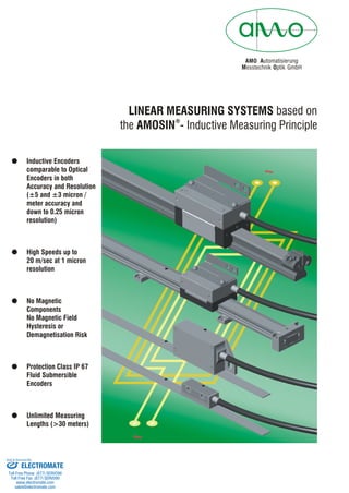
  • 1. AMO Automatisierung M Oesstechnik ptik GmbH LINEAR MEASURING SYSTEMS based on the AMOSIN - Inductive Measuring Principle ® ! Inductive Encoders comparable to Optical Encoders in both Accuracy and Resolution ( ! High Speeds up to 20 m/sec at 1 micron resolution ! ! ! ±5 and ±3 micron / meter accuracy and down to 0.25 micron resolution) No Magnetic Components No Magnetic Field Hysteresis or Demagnetisation Risk Protection Class IP 67 Fluid Submersible Encoders Unlimited Measuring Lengths (>30 meters) ELECTROMATE Toll Free Phone (877) SERVO98 Toll Free Fax (877) SERV099 www.electromate.com sales@electromate.com Sold & Serviced By:
  • 2. ® AMOSIN - general information AMO's proven and original technology for length- and angle measurements uses techniques for scanning high precision graduations consists of structures photo-lithographically etched onto steel. Based on this, inductive sensors with integrated evaluation electronics (in ASIC) have been developed further, to create a new and powerful generation of measuring systems. ® The AMOSIN length measuring systems are supplied in 2 principal versions: an open, non-contacting system, or as a guided, encapsulated system. ® Operating entirely on an inductive basis, the AMOSIN systems achieve high precisions of up to +/- 5 µm/m, but are nevertheless very well able to resist environmental influences such as dust, humidity and so forth, also featuring an extremely high resistance to shock and vibration. The high precision is mainly due to the procedure used to manufacture the rigid steel measuring tape, and to the exceptionally high quality sensor signal, with deviations in the sine wave down to < 0.1 % harmonic content, as a measure of the achievable interpolati- on precision within the grating pitch. As will be seen from the measuring principle described below, the measuring system does not include any magnetic parts (weither in the measuring scale nor in the scanning head). As a result it is not at all sensitive to electromagnetic interference of any kind and has no hysteresis, in contrast to magnetic measuring systems. The systems output interface is either 1 Vpp sine/cosine signals, or RS-422 square wave signals, in real-time. Not sensitive to soiling / IP 67 Not sensitive to interfering magnetic fields High precision and resolution General properties High dynamic range No functional hysteresis Integrated reference mark,also distance coded Machine tools Direct drives Metal plate working machines SMT-pick and place machines Measuring machines Typical applications Handling Printing machines Punching machines Electronic production equipment Hydraulic axes Properties - the new generation Analog output signals (1 Vpp) can also be delivered with a reduced signal period of 40 µm Digital output RS-422 / TTL with decimal resolution: 0.25 µm (1000 µm/4000) and 1µm (1000 µm/1000) Introduction of the product group with a grating pitch of 3000 µm for high mounting tolerances. The standard working temperature range has been enlarged to 0-70 °C. Dependency of the precision of the system on the operating temperature has been significantly reduced. Scanning head clearance (air gap between the scanning head and the measuring tape) and its tolerance have been increased. The effects of mounting deviations within the specified tolerances on the precision of the system have been greatly reduced. Miniaturisation of the evaluation electronics, which has permitted integration of this circuitry into the connector housing. 2 ELECTROMATE Toll Free Phone (877) SERVO98 Toll Free Fax (877) SERV099 www.electromate.com sales@electromate.com Sold & Serviced By:
  • 3. ® The AMOSIN measuring systems function on the principle of a transformer with a moving reluctance core. The mutual inductance of the primary and secondary windings of a transformer changes in accordancewiththerelativepositionofthecore. The AMOSIN system consists primarily of a planar coil and a measuring scale (Fig.1). The coil structure, with a number of winding elements (individual main elements with primary and secondary SIN/COS coils) aligned in the direction of measurement, is implemented on a substrate using micro-multi-layer technology. The measu- ring scale is a stainless-steel tape onto which a highly precise graduation (e.g. l = 1000 µm) of variable reluctance has been etched using photo- lithographictechniques. The relative movement in the direction of measurement between the sensor structure (in the scanning head) and the measuring scale periodically changes the mutual inductance of the individual coils, generating two sinusoidal signals with a 90° phase difference (SIN and COS). The extremely accurate signal, and its immunity to environmental influences, has the effect that, after conditioning of the signal in the evaluation electronics (Fig. 2), deviations of no more than 0.1% from the ideal sinusoidal form (harmonic content) remains. This allows high interpolation factors (further levels of sub-division) to be carried out in the course of signal digitisation. This can either be done in the measuring system itself, or in the subsequent electronics (CNC etc.). An important feature of the principle of operation is that using ® the AMOSIN procedure does not give rise to any measurement hysteresis (mach-ine backlash error). In contrast to magnetic systems, the high-frequency alternating field sup-presses any hysteresis in the material. The evaluation electronics con- ditions the sensor signals and interpolates them continuously, without using strobe times, exploiting a novel circuit principle. It then supplies the measurement information at the output through differential interfaces and line drivers, either as a sinusoidal signal or as a square wave signal. (see the signal diagram on Page 23) In addition to the periodic signals (A, B and their inverted) a reference signal is output for the determination of absolute posi- tion. This signal is generated from individual marks integrated into the measuring scale, and does not require any additional parts. (see the description of the reference signal on Page 23) 3 ® AMOSIN - the measuring principle AMOSIN MEASURING SYSTEM (Fig. 2) AMOSIN - MEASURING PRINCIPLE (Fig. 1) Primary windings Secondary windings Micro-coil structure Sensor substrate Measuring scale SIN COS SIN COS EEPROM configuration data Power supply unit ASIC signal conditioning + evaluation Compensation signals Electronic evaluation stage Sensor unit Measuring scale Analog output ~ 1 Vpp Encoder output RS 422 ELECTROMATE Toll Free Phone (877) SERVO98 Toll Free Fax (877) SERV099 www.electromate.com sales@electromate.com Sold & Serviced By:
  • 4. Measuring accuracy The total error of a measuring system is caused by the following measuring inaccuracies: 1. Precision of the graduation - determined by the precision of the measuring scale 2. Precision within one grating pitch - primarily determined by the quality of the sensor signal and its evaluation electronics. The following should also be considered for the measuring systems with a 1 Vpp output interface: 3. Precision of the analog/digital conversion at the input stage of the subsequent electronics (in the controller) 4. Noise coupled into the output signals as it is transferred from the scanning head to the subsequent electronics A detailed description of these aspects follows: 1. Scale accuracy Every measuring scale is measured on a linear test bench, and a test certificate, quoting the precision class in accordance with specification, is completed. Optionally a measuring diagram (measured under ideal mounting conditions) can be supplied, as follows. 2. Precision within one grating pitch ® These errors are extremely small on AMOSIN systems, and are in the region of 0.1 % of the grating pitch (corresponding 1 µm for a grating pitch of 1000 µm). This maximum precision is not just relevant to the ideal set-up, but is also retained when the mounting tolerances and working temperature range are exploited. Every scanning head is adjusted and tested on the basis of these tight criteria of quality. In order to suppress the errors discussed above under points "3" and "4", a new output interface has been implemented in the new ® generation of AMOSIN systems, in which the sine, cosine and reference signals, for the 1 Vpp output interface, are divided and over line drivers (see signal diagram on Page 23). The dividing of the grating pitch (D) generates a signal corresponding to a pitch of 40 µm in real-time, if a measuring scale with a grating pitch of 1000 µm is used. The effect of any possible deviation in the evaluation (A/D conversion) in the subsequent electronics (controller etc.), is reduced in this signal interface by exactly the dividing factor (D) that is applied. In addition, this reduced sinusoidal signal period leads to finer quantisation in the subsequent electronics, which is of particularly great importance to demanding high dynamic and stiff drive applications. Additionally, the signal division reduces the effect of noise coupling on the signal transfer line, in proportion to the dividing factor "D"; in other words, an improved signal/noise ratio is achieved. ® The metrological principle on which the AMOSIN systems operate means that they are entirely free from hysteresis. 4 ELECTROMATE Toll Free Phone (877) SERVO98 Toll Free Fax (877) SERV099 www.electromate.com sales@electromate.com Sold & Serviced By:
  • 5. 5 So that it can be dismounteded, the stainless-steel measuring scale is fixed by means of alignment pins and clamps in the guided, encapsulated measuring systems from the LMI-310 series. In the LMI-200 series, the measuring tape is permanently bonded to the guide rail. In the open, non-contacting systems, a double-sided adhesive foil is applied for direct sticking on the machine bed. In all of these versions, the scanning still takes place without contact, and is therefore not subject to wear. Measuring system configuration Measuring rail Mounting pad Mounting element Measuring slider Cover tape Measuring scale 1. Grating pitch: 2. Type of scanning: 3. Measuring scale: 4. Scanning head: - l = 1000 µm for maximum precision - l = 3000 µm for larger mounting tolerances - open - without contact - guided - encapsulated - measuring tape - measuring rail - miniature version with electronics in connector - fully integrated electronics The main selection criteria are illustrated in the following table. Measuring scale Adhesive tapeCover tape Carrier tape Mounting bracket (on both ends) Mounting element Measuring slider Cover tape Measuring scale with carrier tape Adjusting screw Mesuring rail Mounting hole for the measuring rail Scanning head Measuring slider LMK-310 with integrated electronics Measuring rail LMF-310 in single or multiple sections for long measuring axis The scale can be adjusted to compensate axis accuracy LMI-310 Measuring slider LMK-200 - miniature with connector electronics LMK-210 - with integrated electronics(not figured) Miniature measuring rail LMF-200 with welded scale LMI-200 Measuring head LMK-100 - miniature with connector electronics LMK-110 - with integrated electronics(not figured) Measuring scale for direct sticking on the machine base LMI-100 ELECTROMATE Toll Free Phone (877) SERVO98 Toll Free Fax (877) SERV099 www.electromate.com sales@electromate.com Sold & Serviced By:
  • 6. 6 l = 1000 µm l = 3000 µm LMI-100 LMI-110 Selection table: Grating pitch LMI-130 LMI-200 LMI-210 LMI-310 LMB-100 Page 07 LMK-100 Page 07 LMB-110 Page 09 LMK-110 Page 10 - - LMF-200 Page 14 LMK-200 Page 15 LMF-200 Page 17 LMK-210 Page 17 LMF-310 Page 19 LMK-310 Page 21 - - - - LMB-130 Page 12 LMK-130 Page 12 - - - - - - Measuring scale Scanning head miniature Measuring scale Scanning head Measuring scale Scanning head Measuring rail Measuring slider miniature Measuring rail Measuring slider Measuring rail Measuring slider Withoutcontact Open Guided Encapsulated Measuring systems for open, non-contact scanning with grating pitch of l=1000µm Open measuring system Miniature design with connector electronics No wear Ideal for applications with high dynamic range High precision Suited for long axis Devided sinus output of 40 µm LMI-100 Connector dimensions see page 25 Main features: ELECTROMATE Toll Free Phone (877) SERVO98 Toll Free Fax (877) SERV099 www.electromate.com sales@electromate.com Sold & Serviced By:
  • 7. Technical Data: Grating pitch: Linearity error: Coefficient of expansion: Measuring length: Mechanical execution: Reference position: 1000 µm LMB-100.0 =±20 µm LMB-100.1 =±10 µm LMB-100.2 =± 5 µm ~11ppm Up to a maximum of 30 m Stainless-steel measuring tape, with adhesive layer for mounting Normally in the middle, any position and number, or distance-encoded (see description on page 24) 0 LMB-100 measuring tape Tape length in mm LMB-100. - - RI position (like above sketch) 0 ... none 1 ... 50 mm from the left 2 ... central 3 ... 50 mm from the right 4 ... 100 mm from the left 5 ... 100 mm from the right 6 ... 50 mm from both sides 7 ... 100 mm from both sides 8 ... all 100 mm 9 ... Special RI position(s) (requires a special no. Sxx) K1 … distance-coded (basic spacing 40 mm) K2 … distance-coded (basic spacing 80 mm) K3 … distance-coded (basic spacing 120 mm) Ordering code: LMK-10 scanning head Operating temperature: Storage temperature: Protection class: Vibration: Shock: Power supply: Cable: Output signals: Optional: Max. Speed: 0° to 70° C (higher temperatures by request) -20°C to 85°C Scanning head: IP 67 Connector electronics / versions with CONNEI connector: IP 67 Connector electronics / version with 15-pin Sub-D connector: IP 54 2 <400 m/s for 55 - 2000 Hz 2 <2000 m/s for 6 ms See the following table (sensor lines available, see page 26) PUR jacket, high flexibility, dmr. 5.3 mm, 5(2x0.05) + 1 (2x0.14) mm² (Bending radius: 10 x d = 50mm continuous bending; 5 x d = 25mm single bend) ! LMK-101. analog output 1 Vpp to 120 W terminating resistor· with sinus output of 1000 µm or 40 µm ! LMK-102. TTL output - resolution as in the following table Limit switch function (see description on page 22) LED on the connector housing as an assembly aid (by request) W LMK-101.0 LMK-101.3 1 Vpp/1000 µm 1 Vpp/40 µm Type Output signal/resolution 10 m/s 10 m/s Speed LMK-102.0 LMK-102.1 LMK-102.4 LMK-102.5 TTL/10 µm* TTL/5 µm* TTL/1 µm* TTL/0.25 µm* 10 m/s 2.5 m/s 20 m/s 7 Linearity error 0 ... ±20 µm 1 ... ±10 µm 2 ... ± 5 µm0 *) after 4x edge evaluation (see diagram on page 23) 260 mA 260 mA Power Supply 5V ±5% 300 mA ELECTROMATE Toll Free Phone (877) SERVO98 Toll Free Fax (877) SERV099 www.electromate.com sales@electromate.com Sold & Serviced By:
  • 8. LMK-101. -- Ordering code: - Connector / version 5 ... 15-pin Sub-D plug 6 ... 12-pin CONNEI coupling (male) screwed cable gland at the input 6A ... 12-pin input CONNEI coupling (female) output 12-pin CONNEI coupling (male) 0 0 06 ... 6A ... Cable length (in whole metres) 1 ... 1m (preferred length) 2 ... 2m 3 ... 3m (preferred length) X ... special length (may require a special no. Sxx) Signal period 0 ... 1000 m 3 ... 40 m µ µ Limit switch 0 ... none 1 ... with L ... reference pulse selectable Limit switch 0 ... none 1 ... with L ... reference pulse selectable LMK-102. -- - Connector / version 5 ... 15-pin Sub-D plug 6 ... 12-pin CONNEI coupling (male) screwed cable gland at the input 6A ... 12-pin input CONNEI coupling (female) output 12-pin CONNEI coupling (male) 0 0 06 ... 6A ... Cable length (in whole metres) 1 ... 1m (preferred length) 2 ... 2m 3 ... 3m (preferred length) X ... special length (may require a special no. Sxx) Resolution after 4x edge evaluation 0 ... 10 m 1 ... 5 m 4 ... 1 m 5 ... 0.25 m µ µ µ µ 0 0 Scanning head with 1 Vpp output signal – LMK-101 Scanning head with TTL (RS422) output signal – LMK-102 Dimensions: 8 ELECTROMATE Toll Free Phone (877) SERVO98 Toll Free Fax (877) SERV099 www.electromate.com sales@electromate.com Sold & Serviced By:
  • 9. Grating pitch: Linearity error: Coefficient of expansion: Measuring length: Mechanical execution: Reference position: 1 mm LMB-110.0 =±20 µm LMB-110.1 =±10 µm LMB-110.2 =± 5 µm ~11ppm Up to a maximum of 30 m Stainless-steel measuring tape, with adhesive layer for mounting Normally in the middle, any position and number, or distance-coded (see description on page 24) 0 LMB-110 measuring tape Tape length in mm LMB-110. - - RI position (like above sketch) 0 ... none 1 ... 50 mm from the left 2 ... central 3 ... 50 mm from the right 4 ... 100 mm from the left 5 ... 100 mm from the right 6 ... 50 mm from both sides 7 ... 100 mm from both sides 8 ... all 100 mm 9 ... Special RI position(s) (requires a special no. Sxx) K1 … distance-coded (basic spacing 40 mm) K2 … distance-coded (basic spacing 80 mm) K3 … distance-coded (basic spacing 120 mm) Ordering code: Linearity error 0 ... ±20 µm 1 ... ±10 µm 2 ... ± 5 µm0 9 Open measuring system Suited for long axis Devided sinus output of 40 µm Integrated electronics No wear Ideal for applications with high dynamic range High precision Technical Data: Main features: LMI-110 Also available in - design for explosion sensitive environments (see datasheet or www.amo.at) ELECTROMATE Toll Free Phone (877) SERVO98 Toll Free Fax (877) SERV099 www.electromate.com sales@electromate.com Sold & Serviced By:
  • 10. Abtastkopf LMK-11 0°C to 70°C (higher temperatures by request) -20°C to 85°C Scanning head: IP 67 2 <200 m/s for 55 - 2000 Hz 2 <1000 m/s for 6 ms See the following table (sensor lines available, see page 26) PUR jacket, high flexibility, dmr. 5.3 mm, 5(2x0.05) + 1 (2x0.14) mm² (Bending radius: 10 x d = 50mm continuous bending; 5 x d = 25mm single bend) Maximum length 9m, up to 50m with extension cable (see page 26) ! LMK-111. analog output 1 Vpp to 120 W terminating resistor· with sinus output of 1000 µm or 40 µm ! LMK-112. TTL output - resolution as in the following table Limit switch function (see description on page 22) W *) after 4x edge evaluation LMK-111. -- Ordering code: - Signal period 0 ... 1000 m 3 ... 40 m µ µ Scanning head with 1 Vpp output signal - LMK-111 Connector / version 0 ... none 1 ... 12-pin DIN connector 3 ... 9-pin Sub-D plug 4 ... 12-pin CONNEI plug (male) 5 ... 15-pin Sub-D plug 6 ... 12-pin CONNEI coupling (male) 9 ... special connector or special pin-out (requires special no. Sxx)9 ... Cable length (in whole metres) 1 ... 1m (preferred length) 3 ... 3m (preferred length) 9 ... 9 m X ... special length (may require a special no. Sxx) LMK-112. -- - Scanning head with TTL (RS422) output signal - LMK-112 Connector / version 0 ... none 1 ... 12-pin DIN connector 3 ... 9-pin Sub-D plug 4 ... 12-pin CONNEI plug (male) 5 ... 15-pin Sub-D plug 6 ... 12-pin CONNEI coupling (male) 9 ... special connector or special pin-out (requires special no. Sxx)9 ... Cable length (in whole metres) 1 ... 1m (preferred length) 3 ... 3m (preferred length) 9 ... 9 m X ... special length (may require a special no. Sxx) Resolution after 4x edge evaluation 0 ... 10 m 1 ... 5 m 4 ... 1 m 5 ... 0.25 m µ µ µ µ 0 0 10 Operating temperature: Storage temperature: Protection class: Vibration: Shock: Power supply: Cable: Output signals: Optional: Max. Speed: (see diagram on page 23) Limit switch 0 ... none 1 ... with L ... reference pulse selectable Limit switch 0 ... none 1 ... with L ... reference pulse selectable LMK-111.0 LMK-111.3 1 Vpp/1000 µm 1 Vpp/40 µm Type Output signal/resolution 10 m/s 10 m/s Speed LMK-112.0 LMK-112.1 LMK-112.4 LMK-112.5 TTL/10 µm* TTL/5 µm* TTL/1 µm* TTL/0.25 µm* 10 m/s 2.5 m/s 20 m/s 200 mA Power Supply 5V ±5% 260 mA * * The - option is designated - EX2* ELECTROMATE Toll Free Phone (877) SERVO98 Toll Free Fax (877) SERV099 www.electromate.com sales@electromate.com Sold & Serviced By:
  • 11. Dimensions: Measuring systems for open, non-contact scanning with grating pitch of l=3000µm Open measuring system Integrated electronics No wear Wide mounting tolerances LMI-130 11 Main features: Also available in - design for explosion sensitive environments (see datasheet or www.amo.at) ELECTROMATE Toll Free Phone (877) SERVO98 Toll Free Fax (877) SERV099 www.electromate.com sales@electromate.com Sold & Serviced By:
  • 12. Technical Data: Grating pitch: Linearity error: Coefficient of expansion: Measuring length: Mechanical execution: Reference position: 3 mm LMB-130.0 =±20 µm ~11ppm Up to a maximum of 30 m Stainless-steel measuring tape, with adhesive layer for mounting Normally in the middle, any position is possible LMB-130 measuring tape Tape length in mm LMB-130. - - RI position (like above sketch) 0 ... none 1 ... 50 mm from the left 2 ... central 3 ... 50 mm from the right 4 ... 100 mm from the left 5 ... 100 mm from the right 6 ... 30 mm from both sides 7 ... 60 mm from both sides 8 ... all 90 mm 9 ... Special RI position(s) (requires a special no. Sxx) Ordering code: Abtastkopf LMK-13 0° to 70° C (higher temperatures by request) -20°C to 85°C Scanning head: IP 67 2 <200 m/s for 55 - 2000 Hz 2 <1000 m/s for 6 ms See the following table (sensor lines available, see page 26) PUR jacket, high flexibility, dmr. 5.3 mm, 5(2x0.05) + 1 (2x0.14) mm² (Bending radius: 10 x d = 50mm continuous bending; 5 x d = 25mm single bend) Maximum length 9m, up to 50m with extension cable (see page 26) ! LMK-131. analog output 1 Vpp to 120 W terminating resistor ! LMK-132. TTL output - resolution as in the following table Limit switch function (see description on page 22) W LMK-131.0 LMK-131.3 1 Vpp/3000 µm 1 Vpp/120 µm Type Output signal/resolution 30 m/s 30 m/s Speed LMK-132.0 LMK-132.1 LMK-132.4 LMK-132.5 TTL/30 µm* TTL/15 µm* TTL/3 µm* TTL/0.75 µm* 30 m/s 7.5 m/s 60 m/s Linearity error 0 ... ±20 µm *) after 4x edge evaluation 12 Operating temperature: Storage temperature: Protection class: Vibration: Shock: Power supply: Cable: Output signals: Optional: Max. Speed: (see diagram on page 23) 200 mA Power Supply 5V ±5% 260 mA ELECTROMATE Toll Free Phone (877) SERVO98 Toll Free Fax (877) SERV099 www.electromate.com sales@electromate.com Sold & Serviced By:
  • 13. Limit switch 0 ... none 1 ... with LMK-131. -- Ordering code: - Signal period 0 ... 3000 m 3 ... 120 m µ µ Scanning head with 1 Vpp output signal - LMK-131 Connector / version 0 ... none 1 ... 12-pin DIN connector 3 ... 9-pin Sub-D plug 4 ... 12-pin CONNEI plug (male) 5 ... 15-pin Sub-D plug 6 ... 12-pin CONNEI coupling (male) 9 ... special connector or special pin-out (requires special no. Sxx)9 ... Cable length (in whole metres) 1 ... 1m (preferred length) 3 ... 3m (preferred length) 9 ... 9 m X ... special length (may require a special no. Sxx) LMK-132. -- - Scanning head with TTL (RS422) output signal - LMK-132 Connector / version 0 ... none 1 ... 12-pin DIN connector 3 ... 9-pin Sub-D plug 4 ... 12-pin CONNEI plug (male) 5 ... 15-pin Sub-D plug 6 ... 12-pin CONNEI coupling (male) 9 ... special connector or special pin-out (requires special no. Sxx)9 ... Cable length (in whole metres) 1 ... 1m (preferred length) 3 ... 3m (preferred length) 9 ... 9 m X ... special length (may require a special no. Sxx) Resolution after 4x edge evaluation 0 ... 30 m 1 ... 15 m 4 ... 3 m 5 ... 0.75 m µ µ µ µ 0 Dimensions: 13 Limit switch 0 ... none 1 ... with L ... reference pulse selectable The - option is designated - EX2* * * ELECTROMATE Toll Free Phone (877) SERVO98 Toll Free Fax (877) SERV099 www.electromate.com sales@electromate.com Sold & Serviced By:
  • 14. Measuring systems for guided - encapsulated scanning with grating pitch of l=1000µm Miniature measuring rail Miniature measuring slider with connector electronics Stainless-steel version Ideal for tough environment High precision Large mounting tolerances of±1 mm over flexure element LMI-200 Technical Data: Grating pitch: Accuracy: Coefficient of expansion: Measuring length: Reference position: 1 mm LMF-200.0 =±20 µm LMF-200.1 =±10 µm LMF-200.2 =± 5 µm ~11ppm 120 / 170 / 220 / 270 / 320 / 420 / 520 / 620 / 720 / 820 / 920 / 1020 mm Longer lengths by request Standard in the middle, any position and number, or distance-coded (see description on page 24) 0 LMF-200 measuring rail Measuring length in mm Standard: 120 / 170 / 220 / 270 / 320 / 420 / 520 / 620 / 720 / 820 / 920 / 1020 Longer lengths by request LMF-200. - - RI position (like above sketch) 0 ... none 1 ... 50 mm from the left 2 ... central 3 ... 50 mm from the right 4 ... 100 mm from the left 5 ... 100 mm from the right 6 ... 50 mm from both sides 7 ... 100 mm from both sides 8 ... all 100 mm 9 ... Special RI position(s) (requires a special no. Sxx) K1 … distance-coded (basic spacing 40 mm) K2 … distance-coded (basic spacing 80 mm) K3 … distance-coded (basic spacing 120 mm) Ordering code: Accuracy 0 ... ±20 µm 1 ... ±10 µm 2 ... ± 5 µm0 14 Connector dimensions see page 25 Main features: ELECTROMATE Toll Free Phone (877) SERVO98 Toll Free Fax (877) SERV099 www.electromate.com sales@electromate.com Sold & Serviced By:
  • 15. LMK-20 - measuring slider 0° to 70° C (higher temperatures by request) -20°C to 85°C Scanning head: IP 67 Connector electronics / versions with CONNEI connector: IP 67 Connector electronics / version with 15-pin Sub-D connector: IP 54 See the following table (sensor lines available, see page 26) PUR jacket, high flexibility, dmr. 5.3 mm, 5(2x0.05) + 1 (2x0.14) mm² (Bending radius: 10 x d = 50mm continuous bending; 5 x d = 25mm single bend) ! LMK-201. analog output 1 Vpp to 120 W terminating resistor· with sinus output of 1000 µm or 40 µm ! LMK-202. TTL output - resolution as in the following table Limit switch function (see description on page 22) LED on the connector housing as an assembly aid (by request) W LMK-201.0 LMK-201.3 1 Vpp/1000 µm 1 Vpp/40 µm Type Output signal/resolution 1) 3 m/s 1) 3 m/s Speed LMK-202.0 LMK-202.1 LMK-202.4 LMK-202.5 2) TTL/10 µm 2) TTL/5 µm 2) TTL/1 µm 2) TTL/0.25 µm 1) 3 m/s 2.5 m/s 3 m/s 1) 1) 2) limited by the mechanics after 4x edge evaluation LMK-201. -- Ordering code: - Connector / version 5 ... 15-pin Sub-D plug 6 ... 12-pin CONNEI coupling (male) screwed cable gland at the input 6A ... 12-pin input CONNEI coupling (female) output 12-pin CONNEI coupling (male) 0 0 06 ... 6A ... Cable length (in whole metres) 1 ... 1m (preferred length) 2 ... 2m 3 ... 3m (preferred length) X ... special length (may require a special no. Sxx) Signal period 0 ... 1000 m 3 ... 40 m µ µ LMK-202. -- - Connector / version 5 ... 15-pin Sub-D plug 6 ... 12-pin CONNEI coupling (male) screwed cable gland at the input 6A ... 12-pin input CONNEI coupling (female) output 12-pin CONNEI coupling (male) 0 0 06 ... 6A ... Cable length (in whole metres) 1 ... 1m (preferred length) 2 ... 2m 3 ... 3m (preferred length) X ... special length (may require a special no. Sxx) Resolution after 4x edge evaluation 0 ... 10 m 1 ... 5 m 4 ... 1 m 5 ... 0.25 m µ µ µ µ 0 0 Measuring slider with 1 Vpp output signal evaluation - LMK-201 Measuring slider with TTL (RS422) output signal - LMK-202 15 Operating temperature: Storage temperature: Protection class: Power supply: Cable: Output signals: Optional: Max. Speed: (see diagram on page 23) Limit switch 0 ... none 1 ... with L ... reference pulse selectable Limit switch 0 ... none 1 ... with L ... reference pulse selectable 260 mA Power Supply 5V ±5% 300 mA ELECTROMATE Toll Free Phone (877) SERVO98 Toll Free Fax (877) SERV099 www.electromate.com sales@electromate.com Sold & Serviced By:
  • 16. 16 LMI-210 Miniature measuring rail Measuring slider with integrated electronics Stainless-steel version Ideal for rough environment High precision Dimensions: Main features: ELECTROMATE Toll Free Phone (877) SERVO98 Toll Free Fax (877) SERV099 www.electromate.com sales@electromate.com Sold & Serviced By:
  • 17. Technical Data: Grating pitch: Accuracy: Coefficient of expansion: Measuring length: Reference position: 1 mm LMF-200.0 =±20 µm LMF-200.1 =±10 µm LMF-200.2 =± 5 µm ~11ppm 120 / 170 / 220 / 270 / 320 / 420 / 520 / 620 / 720 / 820 / 920 / 1020 mm Longer lengths by request Normally in the middle, any position and number, or distance-coded (see description on page 24) 0 LMF-200 measuring rail Measuring length in mm Standard: 120 / 170 / 220 / 270 / 320 / 420 / 520 / 620 / 720 / 820 / 920 / 1020 Longer lengths by request LMF-200. - - RI position (like above sketch) 0 ... none 1 ... 50 mm from the left 2 ... central 3 ... 50 mm from the right 4 ... 100 mm from the left 5 ... 100 mm from the right 6 ... 50 mm from both sides 7 ... 100 mm from both sides 8 ... all 100 mm 9 ... Special RI position(s) (requires a special no. Sxx) K1 … distance-coded (basic spacing 40 mm) K2 … distance-coded (basic spacing 80 mm) K3 … distance-coded (basic spacing 120 mm) Ordering code: Accuracy 0 ... ±20 µm 1 ... ±10 µm 2 ... ± 5 µm0 LMK-21 - measuring slider 0°C to 70°C (higher temperatures by request) -20°C to 85°C Scanning head: IP 67 See the following table (sensor lines available, see page 26) PUR jacket, high flexibility, dmr. 5.3 mm, 5(2x0.05) + 1 (2x0.14) mm² (Bending radius: 10 x d = 50mm continuous bending; 5 x d = 25mm single bend) ! LMK-111. analog output 1 Vpp to 120 W terminating resistor· with sinus output of 1000 µm or 40 µm ! LMK-112. TTL output - resolution as in the following table Limit switch function W LMK-211.0 LMK-211.3 1 Vpp/1000 µm 1 Vpp/40 µm Type Output signal/resolution 1) 3 m/s 1) 3 m/s Speed LMK-212.0 LMK-212.1 LMK-212.4 LMK-212.5 2) TTL/10 µm 2) TTL/5 µm 2) TTL/1 µm 2) TTL/0.25 µm 1) 3 m/s 2.5 m/s 3 m/s 1) 1) 2) limited by the mechanics after 4x edge evaluation 17 Operating temperature: Storage temperature: Protection class: Power supply: Cable: Output signals: Optional: Max. Speed: (see diagram on page 23) 200 mA Power Supply 5V ±5% 260 mA ELECTROMATE Toll Free Phone (877) SERVO98 Toll Free Fax (877) SERV099 www.electromate.com sales@electromate.com Sold & Serviced By:
  • 18. LMK-211. -- - Measuring slider with 1 Vpp output signal - LMK-211 Connector / version 0 ... none 1 ... 12-pin DIN connector 3 ... 9-pin Sub-D plug 4 ... 12-pin CONNEI plug (male) 5 ... 15-pin Sub-D plug 6 ... 12-pin CONNEI coupling (male) 9 ... special connector or special pin-out (requires special no. Sxx)9 ... Cable length (in whole metres) 1 ... 1m (preferred length) 3 ... 3m (preferred length) 9 ... 9 m X ... special length (may require a special no. Sxx) LMK-212. -- - Measuring slider with TTL (RS422) output signal - LMK-212 Connector / version 0 ... none 1 ... 12-pin DIN connector 3 ... 9-pin Sub-D plug 4 ... 12-pin CONNEI plug (male) 5 ... 15-pin Sub-D plug 6 ... 12-pin CONNEI coupling (male) 9 ... special connector or special pin-out (requires special no. Sxx)9 ... Cable length (in whole metres) 1 ... 1m (preferred length) 3 ... 3m (preferred length) 9 ... 9 m X ... special length (may require a special no. Sxx) Resolution after 4x edge evaluation 0 ... 10 m 1 ... 5 m 4 ... 1 m 5 ... 0.25 m µ µ µ µ 0 0 18 Dimensions: Ordering code: Limit switch 0 ... none 1 ... with L ... reference pulse selectable Limit switch 0 ... none 1 ... with L ... reference pulse selectable Signal period 0 ... 1000 m 3 ... 40 m µ µ ELECTROMATE Toll Free Phone (877) SERVO98 Toll Free Fax (877) SERV099 www.electromate.com sales@electromate.com Sold & Serviced By:
  • 19. Measuring systems for guided - encapsulated scanning with grating pitch l=1000µm Robust mechanical design Integrated electronics Ideal for tough environment and long measuring lengths (single or multiple sections) High precision Easy mounting and large ounting tolerances of±1 mm over flexure element LMI-310 Technical Data: Grating pitch: Accuracy: Coefficient of expansion: Measuring length: Reference position: 1 mm LMF-310.0 =±20 µm LMF-310.1 =±10 µm LMF-310.2 =± 5 µm ~11ppm a) One-piece measuring rail: 70, 130, 190, ... ML=((n-1) x 60) - 50 [mm] ML max. 3790 mm n ... number of fastening holes n ³ 3 b) Multi-piece measuring rail: Any desired ML (in steps of 60 mm) but with the condition: ML=((n-1) x 60) - 50 [mm], n ³ 3 Normally in the middle, any position and number, or distance-coded (see description on page 24) 0 LMF-310 measuring rail 19 Dimensions of measuring rail LMF-200 Main features: ELECTROMATE Toll Free Phone (877) SERVO98 Toll Free Fax (877) SERV099 www.electromate.com sales@electromate.com Sold & Serviced By:
  • 20. Measuring length (ML) in mm L max. 3790 mm for one-piece version Any ML for multi-piece version LMF-310. - - RI position (like sketch Page 19) 0 ... none 1 ... 50 mm from the left 2 ... central 3 ... 50 mm from the right 4 ... 100 mm from the left 5 ... 100 mm from the right 6 ... 50 mm from both sides 7 ... 100 mm from both sides 8 ... all 100 mm 9 ... Special RI position(s) (requires a special no. Sxx) K1 … distance-coded (basic spacing 40 mm) K2 … distance-coded (basic spacing 80 mm) K3 … distance-coded (basic spacing 120 mm) Ordering code: Accuracy 0 ... ±20 µm 1 ... ±10 µm 2 ... ± 5 µm0 Surface 0 ... without 1 ... with Cr coating Dimensions: 20 ELECTROMATE Toll Free Phone (877) SERVO98 Toll Free Fax (877) SERV099 www.electromate.com sales@electromate.com Sold & Serviced By:
  • 21. LMK-31 - measuring slider Operating temperature: Storage temperature: Protection class: Power supply: Cable: Output signals: Optional: Max. Speed: 0°C to 70°C (higher temperatures by request) -20°C to 85°C Scanning head: IP 67 See the following table (sensor lines available, see page 26) PUR jacket, high flexibility, dmr. 5.3 mm, 5(2x0.05) + 1 (2x0.14) mm² (Bending radius: 10 x d = 50mm continuous bending; 5 x d = 25mm single bend) Maximum length 9m, up to 50m with extension cable (see page 26) ! LMK-311. analog output 1 Vpp to 120 W terminating resistor with sinus output of 1000 µm or 40 µm ! LMK-312. TTL output - resolution as in the following table Limit switch function (see description on page 22) W 1) 2) limited by the mechanics after 4x edge evaluation Technical Data: 21 (see diagram on page 23) LMK-311.0 LMK-311.3 1 Vpp/1000 µm 1 Vpp/40 µm Type Output signal/resolution 1) 3 m/s 1) 3 m/s Speed LMK-312.0 LMK-312.1 LMK-312.4 LMK-312.5 2) TTL/10 µm 2) TTL/5 µm 2) TTL/1 µm 2) TTL/0.25 µm 1) 3 m/s 2.5 m/s 3 m/s 1) 200 mA Power Supply 5V ±5% 260 mA ELECTROMATE Toll Free Phone (877) SERVO98 Toll Free Fax (877) SERV099 www.electromate.com sales@electromate.com Sold & Serviced By:
  • 22. Connector / version 0 ... none 1 ... 12-pin DIN connector 3 ... 9-pin Sub-D plug 4 ... 12-pin CONNEI plug (male) 5 ... 15-pin Sub-D plug 6 ... 12-pin CONNEI coupling (male) 9 ... special connector or special pin-out (requires special no. Sxx)9 ... Cable length (in whole metres) 1 ... 1m (preferred length) 3 ... 3m (preferred length) 9 ... 9 m X ... special length (may require a special no. Sxx) Signal period 0 ... 1000 m 3 ... 40 m µ µ Surface 0 ... without 1 ... with Cr coating LMK-311. -- Measuring slider with 1 Vpp output signal - LMK-311 - -- - Measuring slider with TTL (RS422) output signal - LMK-312 Surface 0 ... without 1 ... with Cr coating Resolution after 4x edge evaluation 0 ... 10 m 1 ... 5 m 4 ... 1 m 5 ... 0.25 m µ µ µ µ 0 0 LMK-312. Limit switch function The limit switch sensor is located in the centre of the scanning head (see mounting drawing). The limit switch output is implemented as an open-collector circuit (see circuit diagram). Limit switch function output circuit: 22 Connector / version 0 ... none 1 ... 12-pin DIN connector 3 ... 9-pin Sub-D plug 4 ... 12-pin CONNEI plug (male) 5 ... 15-pin Sub-D plug 6 ... 12-pin CONNEI coupling (male) 9 ... special connector or special pin-out (requires special no. Sxx)9 ... Cable length (in whole metres) 1 ... 1m (preferred length) 3 ... 3m (preferred length) 9 ... 9 m X ... special length (may require a special no. Sxx) Ordering code: Limit switch 0 ... none 1 ... with L ... reference pulse selectable Limit switch 0 ... none 1 ... with L ... reference pulse selectable ELECTROMATE Toll Free Phone (877) SERVO98 Toll Free Fax (877) SERV099 www.electromate.com sales@electromate.com Sold & Serviced By:
  • 23. Recommended wiring of the subsequent electronics: Description of the output signals Recommended wiring of the subsequent electronics: • A+, B+, RI+ (and their inverted signals): direct signal output, dividing factor D=1 • A´+, B´+, RI´+ (and their inverted signals): divided signal output with dividing factor D=1 • LL, LR limit switch signals 1 Vpp output signals TTL - RS422 output signals 23 Phase shift 90° ±45° Output period ELECTROMATE Toll Free Phone (877) SERVO98 Toll Free Fax (877) SERV099 www.electromate.com sales@electromate.com Sold & Serviced By:
  • 24. In order to determine the absolute position in the direction of measurement between the scanning head and the measuring tape, a reference track is integrated on to the measuring scale, lying parallel to the measuring track. This reference track consists of one or more reference marks (correspondingly marked on the measuring tape), which are detected by the sensors in the scanning head. They can be realised at any desired position on the measuring tape. Reference pulse in the middle of the measured length is the standard configuration. Special positions are possible (see the ordering codes). Description of the reference marks First basic mark K=XX Positive direction of counting Basic spacing Signal not divided (dividing factor D=1) All LMI systems with measuring pitch of 1 mm are offered with coded reference marks having the following basic spacings (K): Signal subject to analog division (dividing factor D = 1) 24 The reference marks can be arranged in the following ways. Coded positioning of the reference marks on the measuring tape allows the controller (in case this one has such an implemented function), to determine the absolute position of the slider after passing over two consecutive coded marks. Basic spacing K (mm) 40K 1 720 80K 2 3120 120K 3 7080 Max. measuring length (mm) MLmax 1. Single reference marks - fix position 3. Distance-coded reference marks Identifier: Identifier: The reference pulse in the desired resolution is validate at the output through a magnet switch. The movement of the measuring slider along the measuring stroke near the switch magnet (delivered for this configuration as in the drawings page 8, 11, 13, 16, 18, 20) triggers the reference pulse. The traveling direction for reference mark (home position) must be always the same to get reproductible reference position. The mounting position of the magnet along the measuring scale is free selectable. In this Measuring head configuration is the limit switch option not available. 2. Single reference marks - selectable Identifier: Reference mark Reference mark usually D=25, for 1000 m / 25 = 40 m sinus signal period.µ µ K' = K x D K' –> Number of sinus periods after division at the output of the measuring system K = =K K K K 2 2 2 2+1 -1 +2 -2 K ³20 ³20 RI RI RI RI RI RI K 2ML =max x (K-2) Count direction RI K 2 +3 K+1 K+1 K' = =K' K K' K' 2 2 2 2+D -D +2D -2D K' ³20 ³20 RI RI RI RI RI RI K' 2ML =max x (K'-2) Count direction RI K' 2 +3D K'+D K'+D K –> Number of sinus periods of 1000 at the output of the measuring system µm ELECTROMATE Toll Free Phone (877) SERVO98 Toll Free Fax (877) SERV099 www.electromate.com sales@electromate.com Sold & Serviced By:
  • 25. 25 Dimensions for connector electronics Connector electronics - design type 6 (see ordering codes) Connector electronics - design type 6A (see ordering codes) Connector electronics - design type 5 (see ordering codes) ELECTROMATE Toll Free Phone (877) SERVO98 Toll Free Fax (877) SERV099 www.electromate.com sales@electromate.com Sold & Serviced By:
  • 26. 26 SUB-D connector 15-pin Sine-wave 1 Vpp or Square-wave output signals TTL Shield on housing PIN Signals 1 B- 2 3 4 5 6 7 8 9 10 11 12 0VA+ LRB+ — RI-+5V Color bluegreen blackbrown greyred white— 39,2 13 4 5 12 321 11109 6 7 8 13 14 15 A- yellow LL violet RI+— pink— — — 13 14 15 0V-Sensor blue-white 5V-Sensor red-white Pin side 9 1 2 3 45 6 7 12 8 11 10 51 26 28 CONNEI- connector adv. coupling 12-pin - plastic-coated metal body Sine-wave 1 Vpp or Square-wave output signals TTL Shield on housing PIN Signals 1 B- 2 3 4 5 6 7 8 9 10 11 12 0VA+ A- B+RI+ RI- +5V Color bluegreen yellow brownpink grey redwhite 5V-Sensor red-white LL violet LR black 0V-Sensor blue-white The sensor lines 0V sensor and 5V sensor are connected internally to the corresponding supply lines. They serve the purpose of checking and readjusting the supply voltage at the device and can also be used parallel to the 0V and 5V supply lines for the purpose of reducing the voltage drop in the line. In case that the option "Limit Switch" is not used, it is not allowed to connect the pins "LL" and "LR" to the following electronics (for example controller). These pins serve alone for test purposes only with the AMO testdevice STU-10. 26 53 25,5 M23x1 9 8 7 6 54 3 2 10 1 11 12 Pin side Connector Coupling — DIN connector 12-pin L120 Square-wave output signals TTL Sine-wave output signals 1 Vpp Shield on housing PIN Signals A B C D E F G H J K L M 0V A+ A- B+ — RI+ RI- — —+5V B- 18 42 70 Pin side K A J H B L C M G F E D —Color blue green yellow brown — pink grey — —red white 30,8 13 4 5 9 321 876 SUB-D connector 9-pin Sine-wave 1 Vpp or Square-wave output signals TTL Shield on housing PIN Signals 1 B- 2 3 4 5 6 7 8 9 0V A+A- B+ RI+RI-— +5V Color blue greenyellow brown pinkgrey— redwhite Measuring system Socket Pin Order designation: -- 00 ... with no Connector 01 ... 12 pin DIN 03 ... 9 pin Sub-D 04 ... 12 pin Connei connectot CW 05 ... 15 pin Sub-D 06 ... 12 pin Connei coupling CCW 09 ... Special connector or special pin assignments 10 ... with no Coupling 11 ... 12 pin DIN 13 ... 9 pin Sub-D (standard) 14 ... 12 pin Connei connector CW 15 ... 15 pin Sub-D 16 ... 12 pin Connei coupling CCW 19 ... Special connector or special pin assignments Cable length in metre VK - 4 - Extension cable Plug and connection assignements Extension cable In case that the option "Limit Switch" is not used, it is not allowed to connect the pins "LL" and "LR" to the following electronics (for example controller). These pins serve alone for test purposes only with the AMO testdevice STU-10. ELECTROMATE Toll Free Phone (877) SERVO98 Toll Free Fax (877) SERV099 www.electromate.com sales@electromate.com Sold & Serviced By:
  • 27. 27 Digital read out equipments For manual drived equipments or the retrofitting of conventional machines for the visualisation of the measuring values (length or angle) can be used the DRO type (DP-10, DP-20, DP-30) Please ask for documentation. Main Features Reset Preset Reference point Absolute chain distances mm/inch switch Tool correction Angle measurement (optional) Linear compensation Radius/diameter switching Speed measurement Resolution programable Counting direction programable Battery back up (optional) Supply 220V or 110 V Interface RS 232 (optional) ELECTROMATE Toll Free Phone (877) SERVO98 Toll Free Fax (877) SERV099 www.electromate.com sales@electromate.com Sold & Serviced By: