
Recommended
More Related Content
What's hot
What's hot (20)
Similar to Laying Underground Power Cables
Similar to Laying Underground Power Cables (20)
Recently uploaded
Recently uploaded (20)
Laying Underground Power Cables
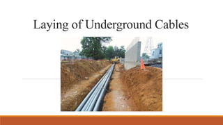
- 1. Laying of Underground Cables
- 2. Introduction • The power from generation stations can be transmitted by cables also. • An electric cable may be defined as a single conductor insulated through its full length. • On the other hand, if two or more conductors each provided with its own insulation and laid up together under one outer protective covering is known as underground cables. • In modern cities and towns, the distribution of power by bare conductors is avoided for safety point of view and cables laid in air are not pleasing to eye. • The underground system of electrical distribution of power is costly system of distribution as compared to overhead system.
- 3. Advantages of underground system 1. Less prone to damage from storms, lightning, accidents, etc. 2. Ensures continuity of supply. 3. Long life as they are less exposed to weather-related deterioration. 4. Transmission losses are reduced due to insulation and reduced exposure to weather-related factors, resulting in more efficient electricity transmission. 5. Requires less maintenance. 6. Better general appearance and suitable for congested areas. 7. Underground cables produce less electromagnetic interference compared to overhead lines.
- 4. Requirements of Cables • The conductor used in cable should be stranded to provide flexibility to the cable and should be of such cross-sectional area that may carry desired current without overheating and causing voltage drop within limits. •Insulation provided should be of such thickness that may give high degree of safety and reliability at the working voltage for which it is designed. • The cable should be provided with mechanical protection so that it may withstand rough usage in laying it. • Material used in manufacturing of cables should be such as to give complete chemical and physical stability throughout its life.
- 5. Classification of Cables Based on voltage 1. L.T cables- operating voltage upto 1000 Volts. 2. H.T cables- operating voltage upto 11000 Volts. 3. S.T cables- operating voltage upto 33000 Volts. 4. Extra high tension (E.H.T) cables- operating voltage upto 132000 Volts. 5. Extra super voltage power cables- operating voltage beyond 132 kV.
- 6. Based on number of cores: • Single-Core Cables: Have one conductor enclosed by insulation. • Multi-Core Cables: Have multiple conductors enclosed by insulation, often used for power distribution.
- 7. Based on Construction: • Unarmored Cables: Cables without additional protective layers, suitable for environments with minimal mechanical stress. • Armored Cables: Cables with an additional layer of armor (usually metal wires) to provide protection against mechanical damage. • Screened or Shielded Cables: Cables with a metallic shield or screen to reduce electromagnetic interference and enhance signal integrity.
- 8. Based on Insulation Material: • Paper-Insulated Cables: Older cables insulated with layers of paper and impregnated with insulating oil. • Polymeric-Insulated Cables: Modern cables with insulating materials like cross-linked polyethylene (XLPE) or ethylene propylene rubber (EPR).
- 9. Inspection of Underground Cables • On arrival of cable packing at site, it should be checked against despatch particulars. • Any loss of packages in transit should be intimated immediately to manufacturer. • The packing case bears some marking indicating the sender and receiver addresses, the way bill number as well as warning in connection with their handling etc. •The size and type of cable should be inspected to detect possible labelling errors by manufacturer.
- 10. Transportation and handling of cables • The cable drums are transported to site on special truck. • This type of truck is equipped with winch to facilitate loading and unloading of cable drums. • The cable drums are secured by strong ropes with them to avoid free fall.
- 11. Precautions while handling the cable 1. While opening the cable drum, proper care should be exercised to ensure that the tools used for opening do not damage the cable. 2. Before laying, all new cables should be megger tested before jointing. After the jointing is complete, all low voltage cables should be megger tested and high voltage cables should be pressure tested before commissioning. 3. The cable should be tested for a) Continuity b) absence of cross phasing (X-phasing), c) insulation resistance to earth d) insulation resistance between conductors.
- 12. 4. If the drum is to be rolled, it should be done in direction indicated by arrow on drum. If arrow mark is illegible, drum should be rolled in a direction opposite to that in which cable is wound, otherwise cable will get loose and damaged while rolling around ground. 5. The drum should be fixed on stands for a free movement of cable when it is pulled. The cable should be unrolled with the drum in such a position that the cable end being pulled is at the top instead of bottom to avoid damage to cable because of rubbing against ground.
- 13. 6. The cable should be unwound from a damage drum with the help of a rotating turn table. Without turntable, the cable will get twisted and may result in breakage of stranded wires, cracking and tearing of insulation. 7. Drums should never be unloaded by dropping then from truck. Cranes, hoists or well supported ramp arrangements are used for proper unloading of drums. Sometimes, drum may be allowed to roll loosely on small slopes with strong rope to prevent loss of control over the drum.
- 14. Storing of cable drum at store yard • All cable drums transported to depot for storing are arranged in such a manner so that free circulation of air between them takes places. • The concrete floor with adequate drainage facilities is preferred so that flanges of drums are not rotten. It also make the rolling of drums easy. • If cable drums are to be stored in open space, the selected site is to be levelled up. • The elevated land having firm soil is preferred for cable depot. • The open depot is also to be protected by barbed wire. • The life of cable depends on proper storing, transporting, rolling and mounting of cable drums before the cable is finally laid in trenches.
- 15. Cable handling equipment • The handling of power cables can be greatly facilitated by having available properly designed plant, such as jacks, rollers and winches. • For use where cables have to be installed at any height above ground level, rollers of hanging type will be required. • These consists of a suitable roller running in a simple U-shaped iron frame designed to open at one side to permit removal after the cable is in position. • It is important that drum should rotate smoothly and with as little vibration as possible and for this reason the spindle used should suit the hole provided in the drum and be of adequate strength and stiffness. Jack Rollers Spindle
- 16. Laying of Underground Cables Before laying cable under the ground, its route should be surveyed and the position of water mains or drains etc. should be ascertained. The cable to be laid underground must have following properties: ◦ The moisture of soil should not enter the core of the cable. ◦ It must have high insulation resistance. ◦ It should be sufficiently flexible. ◦ It should not be costly. ◦ It should not be bulky. ◦ It should be able to withstand the heat produced due to flow of current. ◦ It should not be damaged while handling or laying in the ground. Due to this armoured cables are used.
- 17. Steps involved in laying of underground cable 1. Route of Cable ◦ The shortest possible route having minimum bends is chosen. ◦ Cable route depends on factors such as obstructions caused by building and crossing of roads or streets. ◦ Wherever possible it is desirable to lay cables along the road so that fault detection and repair is easy to carry out. ◦ Avoid places where soil contains ash, excessive chloride, alkalies to avoid corrosion of metal sheath and armour of cable.
- 18. 2. Trenches for laying cable in ground ◦ A trench is dug out in ground along the planned route of cable. ◦ The depth of dug varies according to voltage at which cable is operating. ◦ The width of trench depends on number of cables to be buried. ◦ When more than one cable is placed in same trench, a horizontal spacing should be between 0.25 to 0.4 m in order to reduce the effect of mutual heating and also to ensure fault occurring on one cable does not damage the adjacent cable.
- 19. 3. Unwinding cable from cable drum • Lay off the cable on ground near the drum in series of loops one above the other in the form of figure eight, crossing the cable back and forth on itself and at the same time taking care to keep the turns well above minimum bending radius. • When the whole length of cable has been removed from drum inside end if the cable will then be on top and can be pulled along towards its final position on rollers in the same manner as if cable was coming off the drum itself, with the difference that men must be stationed at the pipe of cable to hand out the turns keeping the bends open and maintaining them in a horizontal place. • Under cold conditions, there is a natural loss of flexibility due to impregnating compound being at low temperature, and the insulation may possibly be damaged when the cable is disturbed in the process of laying. This is particularly important with high voltage cables and if temperature is 40°F, the operation should be postponed, if possible or alternative steps should betaken to warm the drum for a suitable period before hand.
- 20. 4. Laying • Pulling of cables • Methods of laying • Road crossing • Railway crossing • Crossing water mains • Clearance from communication cables 5. Maintenance of cable- Maintaining power cables is crucial to ensure their longevity, reliability, and safety. Proper maintenance practices can help prevent downtime, reduce the risk of electrical hazards, and extend the lifespan of the cables.
- 21. Laying cable in trenches Preparatory work- It includes delivery of required amount of brick, sand, steel, and cement pipes of at least 100 mm diameter. The location of underground constructions shall be thoroughly examined before excavation. Digging out trenches- • Long trenches are dug out by means of special rotor-type trench diggers, whereas short trenches are dug out manually. • Trenches shall be at least 700 mm deep and wide enough to ensure a spacing of at least 100 mm between adjacent parallel cables for up to 100 kV service and at least 50 mm between trench wall and extreme cable. • Where the cable route is curved, the trench is to be made so as to make it possible to lay cable within the desired bending radius.
- 22. Minimum bending radius- For impregnated paper insulated cables up to 33 kV
- 23. Delivery of cable drums to installation site- ◦ Through trucks equipped with winches to facilitate loading and unloading od cable drums. ◦ Cables delivered on site are reeled off drum by means of cable laying vehicles, by winches over pulleys, manually over pulleys or without pulleys.
- 24. Unreeling the cable and placing it in trench- ◦ The cable is to be reeled off from the top and not from bottom. ◦ Prior to unreeling of the cable, linear and angle pulleys shall be mounted in the trench and spaced 2m apart, angle rollers are placed where the trench is curved. ◦ To perform this procedure manually, the workmen place the cable on their shoulders and slowly move along the trench edge or along the bottom. ◦ The cable shall be placed on same side of the workmen shoulders and it will help to avoid any injury at the time of lowering the cable down the ground. ◦ The cable should be lowered simultaneously and shall never be dropped into the ground to prevent accident and damage to cable. ◦ Once laid in trench, the cable shall be checked for crossing clearances to nearby underground structures.
- 25. Back filling of trench • After placing the cable in trench on entire route, the rollers are removed from the position by lifting the cable to small height. The laid cable is then straightened with the help of a flat piece of wood. • The position of the cable in the trench is adjusted to ensure that the cable is in centre if bed. If multiple cables in same trench, spacing between cables should be adjusted as per I.S.S. • After setting the cable in correct position in trench, it is covered with a layer of sand about 10 cm thick. The bricks are used for covering cables. • After placing protective covering on bedding, the trench is back filled with excavated soil in layers. Each layer should be well rammed before application of next layer. The trench may be watered for better consolidation of soil. • Lastly the crowning of soil in the centre of trench is done up to height of 5 to 10 cm for future setting.
- 26. Methods of laying underground cables The conventional methods of laying underground cables are: a) Directly laying in the ground b) Drawing in pipes or ducts or drawn-in system c) Solid system a) Directly laying in ground • Cables are laid direct into the trench. The soil at bed of trench is riddled and levelled before cable is laid. • A trench of 1.2/1.5 m deep and 0.5 m wide for single cable and more width is required if more than one cables are to be accommodated because horizontal interaxial spacing 0.25 m to 0.4 m between 2 consecutive cables has to be maintained to ensure heat dissipation. • When the soil contains large stones or pieces of rock then sand should be used for bedding on which cable is laid and for covering cables. • Type of cable for direct laying- The cable with efficient steel tape or wire armouring are laid direct as they afford excellent protection from mechanical damage. The paper insulated cables for direct laying are usually served finished with one or two layers of cotton, jute.
- 27. Advantages of Direct Cable Laying: 1.Cost-Efficiency: Lower installation expenses due to fewer materials and simpler process. 2.Simplicity: Faster and easier installation without conduits. 3.Space Saving: Direct burial requires less space than using protective conduits. 4.Less Maintenance: Fewer components to maintain over time. Disadvantages of Direct Cable Laying: 1.Limited Protection: Cables are exposed to environmental factors, increasing the risk of damage. 2.Limited Flexibility: Changes and upgrades require excavation work. 3.Durability Concerns: Cables might have a shorter lifespan due to exposure.
- 28. b) Draw-in system ◦ Ducts or pipes are laid in trench for whole of cable route with manholes at suitable position. ◦ This method will apply where later alterations or additions to the system are visualised, since with suitable spare pipes provided in initial installations, further cables can be drawn in without reopening ground. ◦ The internal diameter of ducts should not be less than 1.7 times the diameter of cable, so that cable can be pulled obstruction free. ◦ The depth of trench should be such that top pipe remains at least 60 cm below the ground level. ◦ The width of trench depends on number of pipes to be accommodated. Normally a spacing of 25 cm to 75 cm is maintained between two adjacent pipes.
- 30. C) Solid system ◦ The cables are laid in troughs made of stoneware or wood or cement concrete or cast iron. ◦ Inside troughs, a layer of bituminous material of about 12mm thick is applied. ◦ The spacers are set along trough route at intervals of 45 cm to 50 cm. ◦ The armoured cables are generally preferred for solid system of laying. ◦ The solid system of laying is very seldom adopted in India because of higher initial cost and greater time for installation.
- 31. Advantages: 1. Enhanced Protection: Cables are shielded from physical damage, moisture, and environmental factors. 2. Reduced Damage Risk: Minimized chance of accidental damage during construction or digging. 3. Organized Management: Compartments allow separation of cable types for easy maintenance and upgrades. 4. Easier Maintenance: Simplified cable access and replacement compared to direct burial. 5. Longer Lifespan: Cables' integrity is better preserved, leading to increased longevity. 6. Safety Improvement: Decreased risk of electrical hazards and cable-related accidents. Disadvantages: 1. More expensive than direct laying system 2. Laying and repair requires more time. 3. Laying and repair cannot be carried out in rainy season. 4. Skilled supervision is essential.
- 32. Cable laying across various locations Cables on trays •Power cables are often laid on trays on brackets in buildings, power houses, substations, tunnels and factories. • The trays are made of mild steel sheet and supported on steel framework. • The trays provide continuous support for cables and therefore no sagging of cable occurs. • Sometimes trays are fabricated in tier formation to accommodate good number of cables of different voltages.
- 33. Laying cables on brackets, racks and cleats • This type of cable laying takes place inside building. • The system is employed for big factories, generating stations, substations, power houses and tunnels, etc. • Brackets are made of mild steel sheets supported on steel framework. • This method is used when a number of cables have to be laid horizontally along the same route, specially if cables are unarmoured and when it is not possible to lay them directly in ground or duct. • Cleats are used to grip and hold the cables firmly in position. The cleats are nailed on wall and are made in two sections. Brackets Cleats
- 34. Cables laying at River crossing or Submarine Cable laying • A submarine power cable is a transmission cable for carrying electric power below the surface of the water. These are called "submarine" because they usually carry electric power beneath water. • The purpose of submarine power cables is the transport of electric current at high voltage. • The cables should have characteristics that it is double wire armoured, paper insulated, lead sheathed power cable with impervious outer protective serving. • The armouring of the cable should be strong enough to withstand the pressure of tide of fast flowing river water current.
- 35. • The installation of cable across river is started by loading the cable drum on barge and mounted on a specifically designed reel setup. • One end of cable is the hauled to its appropriate shore position and securely anchored, after which the boat is worked across to the opposite shore, paying out the cable as it proceeds. • Every care must be taken to have full control of drum to ensure that speed at which cable is released corresponds exactly with the rate of progress of boat.
- 36. Laying cables on Bridges ◦ In concrete bridges, the designer keeps this aspect in mind and provides covered ducts in the form of pipes or pipe holes for cable laying. Inspection holes with concrete covers are provided at regular intervals to facilitate easy laying of cables. ◦ In steel bridges, the cable laying design should take the vibration factor into consideration. The continuous vibration of bridge member can damage the sheath of cable. To counter this problem, steel pipes are laid on steel bridges and the cables are drawn-in through them.
- 37. Laying cable in tunnel • In tunnel, the cables are normally cleated on wall or laid on earthed racks. • To avoid sag, runoff cables should be kept straight. The same method is maintained throughout the tunnel. • The cable route in the tunnel is marked on the plan of the tunnel.
- 38. Laying cable under railway track • The cables under railway track are carried out strictly in accordance with the rules and specifications of the railway authorities and for that approval of railway authorities is compulsory. • Normally cast iron or R.C.C pipes are used for laying cables under railway track. • The pipe should be laid at a depth of 1 m below the formation level and should extend to a minimum distance of 3 m from the centre of outermost track on either side. Laying of communication cables • Power cables create disturbances in communication circuits if laid together. The desirable horizontal and vertical distance between power and communication cables is 0.6m. • It is desirable that power cables cross at right angles.
- 39. Laying cable under the road • When cables are laid under the roads, cast iron galvanised steel pipes or reinforced concrete pipes are used to carry them. • Steel pipes are preferred because of their high resistance to mechanical damage and ease of installation. • The pipe should be laid at an angle so as to reduce the angle of bend as the cable enters and leaves the road crossing.
- 40. Clearances Clearance between cable line and foundation of buildings: It should be at least 0.6m. Clearance from water pipeline: • Cables shall never be laid in parallel to pipelines in the vertical plane. • In the horizontal plane, they must be routed in parallel to pipelines on condition that there should be clearance of 0.5m from all pipelines. • If it is required to cross power cable with a water supply pipe, a minimum clearance of 0.4m should be provided between water pipe and power mains. Clearance from gas pipelines and petroleum oil: It should be at least 1.0 m Clearance from electrified railways: • Cables should be laid in conduits or in pipes. • The crossing section shall be placed at least 3m from train lines and at least 10 m for electrified railways. Clearance from sewage pipes: It should not be less than 1.25m
- 41. Introduction to cable filling compounds The cable filling compound should have following qualities: a) Good adhesive property b) Low percentage of contraction on cooling c) High softening point d) High flash point e) Does not crack on cooling f) The compound should be perfectly fluid and poured in fairly rapidly into the holes provided. This should enable the compound to adhere to the interior of the box and ensure a sound, watertight seal. g) In cable joint boxes rated upto 11 kV, the bitumen base cable compound trade name “Paracom” is used for filling the sleeve and box. h) But in boxes above 11 kV, the sleeve is filled with oil-resin compound and bitumen base compound is poured into cast iron joint box.
- 42. Epoxy Resin Hardeners – Used in cable joints and terminations. •Epoxy cable joints and terminations are absolutely airtight, impervious to any ingress of moisture and give long trouble free service. •Epoxy cable sealing has number of advantages over cast-iron and lead cable boxes. •They are compact in weight, take shorter time and less labour for installation. •Epoxy resin readily adheres to metals, provide reliable hermetic sealing (airtight). •Epoxy jointing systems are most often used for low and medium and H.V connections of 3.3 kV, 6.6 kV, and 11 kV cables. •Precautions: In mixing or filling the epoxy compound, care should be taken to prevent its contact with human skin and to protect human eyes because compound contains toxic chemical agents that may cause local irritation and inflammation.
- 43. Cable Jointing • The connection of two lengths of cable by a method which ensures a continuous path for unimpeded flow of electric current is called joint or splices. • Whenever two cables are splice together the connection is called a straight splice, however to connect more than two cables together these are known as 3-way, 4-way splices etc. • An electrically sound joint means that the resistance of jointed conductor should not be greater than that of unjointed length of similar conductor. •A mechanically sound joint means that any pulling on finished joint will not disturb the joint.
- 44. Basic electrical and mechanical requirements of conductor joints and terminations: •There must be sufficient contact area between two current carrying surface, e.g. between wire and terminal. Due to sufficient contact area, the surface contact resistance will be minimised. There will also be reduction in voltage drop across the contacts and in amount of heat generated. •A badly soldered joint called dry joint, could also cause trouble and must be rectified before damage is done. •There must be adequate mechanical strength. This aspect is very important where there is possibility of leads being pulled. • When joints are made inside iron casting, the casting should be warmed before the joint box compound is poured in. Box compound should be heated to 250 degree F before pouring in. The compound will shrink when cooling and therefore, topping-up should be done two or three times, to ensure that there are no air pockets inside the joint. • Use the right grade of insulating materials and box compound recommended by the manufacturers.
- 45. Types of Jointing Methods
- 46. Materials required for jointing 1. Organic flux- Widely used for jointing aluminium conductors. (mixture of triethanolamine and flourine) 2. Solder- Main content of solder are tin and lead. 3. Ferrule- It is slotted metal tube made of tinned copper. It is used in jointing cores of two cables end to end. Its size vary according to size of cable. 4. Cast iron joint box- For mechanical protection of taped cores of cables, cast iron joint boxes are used. 5. Sleeve- To protect taped cores against mechanical damage, to prevent moisture and to bond the sheath of cables, sleeve is used. 6. Cables compound- Bitumen base compound is used for filling in cable joint boxes upto 11 kV working voltage. Above 11 kV, oil rosin compound and bitumen base compound is used. 7. Insulating tape- To build insulation over exposed core of cable. 8. Screening- Metallized paper tapes are being used extensively for lapping over insulated cores of power cables rated above 11 kV.
- 47. Cable Termination •The underground cables need to be terminated for connections with electrical equipments, overhead lines etc. •Special care is required to protect the cable from moisture at the termination. This is normally done by terminating paper insulated cables in compound filled cast iron end boxes. •The design of boxes and termination procedure vary according to voltage of cable and type of equipment to which it has to be connected. •For terminating a cable on pole for connection with overhead lines an inverted type outdoor dividing box is used. •But for cable termination to a distribution board, switch gear, transformer, etc an end sealing box has to be employed.
- 48. To design a most desired cable termination box, the following information is of vital importance. 1. Cable particulars 2. Location of installation (indoor or outdoor) 3. Mounting details 4. Type of outgoing connection 5. Other accessories such as joint box compound, type of gland etc.
- 49. Testing and Commissioning of Under Ground Cables After laying and jointing of cables, the following test should be carried out to ensure damage free laying and flawless jointing. •Conductor Resistance Test- It indicates how efficient the joints of cable is. A good joint should have resistance equal to that of conductors of cables. Any higher value of resistance over manufacturer's value would indicate higher contact resistance at joints or terminations. Loosely connected conductors of the cable or poorly sweated joints is responsible for high contact resistance at joints. This overheats the joint assembly of cable on load causes cable failure. •Insulation Resistance Test- This test indicates any moisture ingression into the cable insulation during jointing operation. This test is carried out in case of a cable of short length by an insulation tester. But the above instrument can not be used for measurement of insulation resistance of a long length of cable because of charging current. Insulation resistance of a cable can be measure with fair accuracy by observing the leakage current during pressure test.
- 50. 3. Pressure Test This test gives indication of any damage in the cable or any flaw in joints. Alternating current or direct current can be used for conducting the pressure test. Normally 2 to 3 times the rated voltage of cable is applied either between conductors or between conductors and earth for 15 minutes. The recommendation of Indian Standard in respect of test voltages for cables of different voltage designations should be strictly adhered to. 4. Apart from general inspection and measurement of conductor and insulation resistance, earth continuity etc. are an important test is high voltage.