1. 1
Biometric Encryption™
Colin Soutar, Danny Roberge‡
, Alex Stoianov, Rene Gilroy, and B.V.K. Vijaya Kumar†
Bioscrypt Inc. (formerly Mytec Technologies Inc.),
5450 Explorer Drive, Suite 500
Mississauga, ONT
L4W 5M1
www.bioscrypt.com
‡
currently with Forensic Technologies Inc.
†
Department of Electrical and Computer Engineering, Carnegie Mellon University
The content of this article appears as chapter 22 in ICSA Guide to Cryptography, edited by Randall K.
Nichols, McGraw-Hill (1999)
1 Introduction
1.1 Biometrics
A biometric is defined as a unique, measurable, biological characteristic or trait for automatically
recognizing or verifying the identity of a human being. Statistically analyzing these biological
characteristics has become known as the science of biometrics. These days, biometric technologies are
typically used to analyze human characteristics for security purposes. Five of the most common physical
biometric patterns analyzed for security purposes are the fingerprint, hand, eye, face, and voice.
The use of biometric characteristics as a means of identification is not a new concept. By 1926, law
enforcement officials in several U.S. cities had begun submitting fingerprint cards to the FBI in an effort to
create a database of fingerprints from known criminals. Human experts in the law enforcement field were
subsequently able to manually match fingerprint samples collected at a crime scene against the prints in this
criminal database. Years of research in developing accurate and distinctive fingerprint classification
schemes made these manual matching processes feasible by drastically reducing the required database search
space. Various fingerprint classification schemes are discussed in Lee and Gaensslen. In the early 1960’s
the FBI invested a large amount of time and effort into the development of automated fingerprint
2. 2
identification systems. This automation of biometric identification for law enforcement purposes coincided
with the development of automated systems for non-forensic applications, such as high-security access
control. Fingerprint identification systems have been deployed in access control systems since the late
1960’s. During the 1970’s a biometric product based on measuring the geometry of the hand was
introduced in a number of access control applications. Interest in biometric identification eventually moved
from measuring characteristics of the hand to include characteristics of the eye. In the mid-1980’s the first
system that analyzed the unique patterns of the retina was introduced while, concurrently, work was being
performed to analyze iris patterns.
In the 1990’s, research continues on developing identification systems based on a wide variety of biometric
patterns, such as the traditional biometrics mentioned above (i.e. fingerprint, hand geometry, iris, and retina),
along with the development of voice, signature, palm print, and face recognition systems. A few new,
innovative approaches are also being examined for biometric analysis, such as ear shape, DNA, keystroke
(typing rhythm), and body odor.
Biometric identification consists of two stages: enrollment and verification. During the enrollment stage, a
sample of the designated biometric is acquired. Some unique characteristics or features of this sample are
then extracted to form a biometric template for subsequent comparison purposes. During the verification
stage, an updated biometric sample is acquired. As in enrollment, features of this biometric sample are
extracted. These features are then compared with the previously generated biometric template.
It is convenient to distinguish between the two main objectives of biometric systems: identification and
authentication. Biometric identification is the process of matching an individual to one of a large set of
system users, whereas biometric authentication simply verifies that the individual is who he or she claims to
be. Law enforcement applications typically require the process of biometric identification. For example, a
typical law enforcement application would seek to determine the identity of an individual who has left a
latent fingerprint at the scene of a crime. The law enforcement official would enter the collected fingerprint
and match its template against all the stored templates in the criminal record fingerprint database. This
process may also be termed a one-to-many search. Alternatively, in the process of biometric authentication
the user submits an identity claim to the system. Thus, only one biometric template is retrieved from the
database of users and compared with the verification sample. Authentication is typically used in
circumstances where access is being controlled, whether physical access to a room or building, or access to
3. 3
an electronic system such as the logon to a computer system. Biometric authentication thus processes a one-
to-one match rather than a one-to-many search. For both the identification and the authentication systems, a
threshold will generally be used to determine the match between templates. The setting of this threshold
determines the discrimination sensitivity of the system.
Many systems have been developed for implementing biometric identification and authentication. Even for
a single biometric, such as the fingerprint, there are many different methods used to create the biometric
template. For example, law enforcement has traditionally used a method of extracting and comparing
minutiae points from the fingerprint. Minutiae points are locations where a fingerprint ridge ends or splits in
two. Other fingerprint characteristics are sweat pore location, ridge density, and distance between ridges.
In other systems, the entire fingerprint image may be processed to implement a pattern recognition process,
such as correlation.
1.2 Merger of biometrics with cryptography
With the proliferation of information exchange across the Internet, and the storage of sensitive data on open
networks, cryptography is becoming an increasingly important feature of computer security. Many
cryptographic algorithms are available for securing information, and several have been discussed previously
in this book. In general, data will be secured using a symmetric cipher system, while public-key systems
will be used for digital signatures and for secure key exchange between users. However, regardless of
whether a user deploys a symmetric or a public-key system, the security is dependent on the secrecy of the
secret or private key, respectively. Because of the large size of a cryptographically-strong key, it would
clearly not be feasible to require the user to remember and enter the key each time it is required. Instead, the
user is typically required to choose an easily remembered passcode that is used to encrypt the cryptographic
key. This encrypted key can then be stored on a computer’s hard drive. To retrieve the cryptographic key,
the user is prompted to enter the passcode, which will then be used to decrypt the key.
There are two main problems with the method of passcode security. First, the security of the cryptographic
key, and hence the cipher system, is now only as good as the passcode. Due to practical problems of
remembering various passcodes, some users tend to choose simple words, phrases, or easily remembered
personal data, while others resort to writing the passcode down on an accessible document to avoid data loss.
Obviously these methods pose potential security risks. The second problem concerns the lack of direct
connection between the passcode and the user. Because a passcode is not tied to a user, the system running
4. 4
the cryptographic algorithm is unable to differentiate between the legitimate user and an attacker who
fraudulently acquires the passcode of a legitimate user.
As an alternative to passcode protection, biometric authentication offers a new mechanism for key security
by using a biometric to secure the cryptographic key. Instead of entering a passcode to access the
cryptographic key, the use of this key is guarded by biometric authentication. When a user wishes to access
a secured key, he or she will be prompted to allow for the capture of a biometric sample. If this verification
sample matches the enrollment template, then the key is released and can be used to encrypt or decrypt the
desired data. Thus, biometric authentication can replace the use of passcodes to secure a key. This offers
both convenience, as the user no longer has to remember a passcode, and secure identity confirmation, since
only the valid user can release the key.
There are various methods that can be deployed to secure a key with a biometric. One method involves
remote template matching and key storage. The biometric image is captured and the corresponding template
is sent to a secure location for template comparison. If the user is verified, then the key is released from the
secure location. This provides a convenient mechanism for the user, as they no longer need to remember a
passcode. This method would work well in a physical access application where the templates and keys may
be stored in a secure location physically separated from the image capture device. In this scenario, the
communication line must also be secured to avoid eavesdropper attacks. However, for personal computer
use, the keys would likely be stored in the clear on a user’s hard drive, which is not secure.
A second method involves hiding the cryptographic key within the enrollment template itself via a trusted
(secret) bit-replacement algorithm. Upon successful authentication by the user, this trusted algorithm would
simply extract the key bits from the appropriate locations and release the key into the system.
Unfortunately, this implies that the cryptographic key will be retrieved from the same location in a template
each time a different user is authenticated by the system. Thus, if an attacker could determine the bit
locations that specify the key, then the attacker could reconstruct the embedded key from any of the other
users’ templates. If an attacker had access to the enrollment program then he could determine the locations
of the key by, for example, enrolling several people in the system using identical keys for each enrollment.
The attacker then needs only to locate those bit locations with common information across the templates.
5. 5
A third method is to use data derived directly from a biometric image. Bodo proposed such a method in a
German patent. This patent proposed that data derived from the biometric (in essence, the biometric
template) are used directly as a cryptographic key. However, there are two main problems with this method.
First, as a result of changes in the biometric image due to environmental and physiological factors, the
biometric template is generally not consistent enough to use as a cryptographic key. Secondly, if the
cryptographic key is ever compromised, then the use of that particular biometric is irrevocably lost. In a
system where periodic updating of the cryptographic key is required, this is catastrophic.
An innovative technique for securing a key using a biometric has been developed by Mytec Technologies
Inc., based in Toronto Canada. The solution developed by Mytec does not use an independent, two-stage
process to first authenticate the user and then release the key. Instead, the key is linked with the biometric at
a more fundamental level during enrollment, and is later retrieved using the biometric during verification.
Furthermore, the key is completely independent of the biometric data, which means that, firstly, the use of
the biometric is not forfeited if the key is ever compromised, and secondly, the key can be easily modified or
updated at a later date. The process developed by Mytec Technologies is called Biometric Encryption™.
During enrollment, the Biometric Encryption process combines the biometric image with a digital key to
create a secure block of data, known as a Bioscrypt™. The digital key can be used as a cryptographic key.
The Bioscrypt is secure in that neither the fingerprint nor the key can be independently obtained from it.
During verification, the Biometric Encryption algorithm retrieves the cryptographic key by combining the
biometric image with the Bioscrypt. Thus, Biometric Encryption does not simply provide a yes/no response
in user authentication to facilitate release of a key, but instead retrieves a key that can only be recreated by
combining the biometric image with the Bioscrypt.
Note that Biometric Encryption refers to a process of secure key management. Biometric Encryption does
not directly provide a mechanism for the encryption/decryption of data, but rather provides a replacement to
typical passcode key-protection protocols. Specifically, Biometric Encryption provides a secure method for
key management to complement existing cipher systems.
Although the process of Biometric Encryption can be applied to any biometric image, the initial
implementation was achieved using fingerprint images. The majority of this chapter therefore deals only
with fingerprint images. The application of the Biometric Encryption algorithm to other biometrics is
briefly discussed in the section entitled Biometric Encryption using other biometric templates.
6. 6
2 Biometric Encryption Algorithm
2.1 Image Processing
In contrast to feature-based biometric systems, the Biometric Encryption algorithm processes the entire
fingerprint image. The mechanism of correlation is used as the basis for the algorithm. A general overview
of correlation, as it relates to Biometric Encryption, is given in the following section. More detailed
discussions of correlation and its applications are given in the references by Goodman, Steward and
VanderLugt.
2.2 Correlation
A two-dimensional input image array is denoted by f(x) and its corresponding Fourier transform (FT) mate
by F(u). Here x denotes the space domain and u denotes the spatial frequency domain. The capitalization
of F denotes an array in the Fourier transform domain. Note that although the arrays defined here are two-
dimensional, only a single parameter, i.e. x, is used as the array variable to simplify description of the
process. A filter function, H(u), is derived from an image, f0(x), where the subscript 0 denotes an image
obtained during an enrollment session. The correlation function, c(x), between a subsequent version of the
input, f1(x), obtained during verification and f0(x) is formally defined as ( ) ( ) ( )
∞
∞−
∗
+= dvvxvx 01 ffc , where *
denotes the complex conjugate. In a practical correlation system, the system output is computed as the
inverse Fourier transform (FT-1
) of the product of F1(u) and F0*(u), i.e. ( ) ( ) ( ){ }uuFTx 01
1 ∗−
= FFc , where
F0*(u) is typically represented by the filter function, H(u), that is derived from f0(x). For correlation-based
biometric systems, the biometric template used for identification/authentication is the filter function, H(u).
Normally in the correlation process the filter function H(u) is designed to produce a distinctive correlation
peak (which approximates a delta function) at the output of the system. Such a correlation peak can easily
be identified in a correlator system, and its position can be used to track an object of interest, see Hahn and
Bauchert. Furthermore, a scalar value can be derived from the correlation plane (Kumar and Hassebrook),
and used as a measure of the similarity between f1(x) and f0(x). The process of correlation provides an
effective mechanism for determining the similarity of objects, and has been successfully used for fingerprint
authentication (Stoianov et al). In the next section, it will be demonstrated that the process of correlation
can also be used as the basis for the Biometric Encryption algorithm.
7. 7
2.3 System requirements
The objective of the Biometric Encryption algorithm is to provide a mechanism for the linking and
subsequent retrieval of a digital key using a biometric such as a fingerprint. This digital key can then be
used as a cryptographic key. The important system requirements that apply to a key retrieval system using a
fingerprint are distortion tolerance, discrimination and security.
• Distortion tolerance is the ability of the system to accommodate the day-to-day distortions of the
fingerprint image. These distortions are due to behavioral changes (positioning, rotation, and
deformation), as well as environmental (ambient temperature and humidity) and physiological (moisture
content) conditions. A key retrieval system must be able to consistently produce the correct key for the
different expected versions of a legitimate user’s fingerprint.
• Discrimination is the ability of a system to distinguish between all of the system users’ fingerprints. An
attacker should produce an incorrect key when the attacker’s fingerprint is combined with a legitimate
user’s filter.
• Security of the system means that neither the digital key, nor the legitimate user’s fingerprint, can be
independently extracted from any stored information.
To satisfy these three constraints simultaneously, the process of correlation was used as a mechanism for
linking and retrieving the digital key. As discussed above, correlation is normally used to provide a single
scalar value which indicates the degree of similarity between one input image, f1(x), and another, f0(x), that is
represented by the filter function, H(u). The process of Biometric Encryption, on the other hand, needs to
extract more information than a simple yes/no response from the system. In fact, Biometric Encryption is
designed typically to output 128 bits of information to be used as a cryptographic key. Thus, it is not
immediately evident how the process of correlation can be applied to this procedure. However, it is known
that the process of correlation can be used to design filter functions that are tolerant to distortions in the input
images; see Kumar, or Roberge et al. This distortion tolerance property of the correlation filter is critical to
the implementation of Biometric Encryption. Instead of designing a filter function, H(u), which produces a
simple output pattern, c(x), which approximates a delta function, the process of Biometric Encryption
8. 8
produces a more sophisticated output pattern. This output pattern is linked during enrollment with a
particular digital key, and subsequently regenerated during verification to retrieve the same digital key.
2.4 Design of the filter function
The filter function will be optimized for the following two requirements: that it consistently produces the
same output pattern for a legitimate user, and that it is tolerant to distortions present in the input images. To
provide a degree of distortion tolerance, the filter function is calculated during an enrollment session using a
set of T training images, where T ≥ 1. Denote the T images of the fingerprint by {f0
1
(x), f0
2
(x), …, f0
T
(x)},
where the subscript 0 denotes a training image. The filter function that will be constructed using these
images is denoted by H(u). Note that we may refer to complex-valued functions such as H(u) independently
by their magnitude and phase components, denoted by |H(u)| and ( )uHi
e φ
, respectively. The output pattern
produced in response to f0
t
(x) is given by c0
t
(x) and the Fourier transform of c0
t
(x) is given by
( ) ( ) ( )uuu t
0
t
0 HFC ⋅≡ , where F0
t
(u) is the Fourier transform of the training image, f0
t
(x). The desired output
pattern from the system is denoted by r(x). Note that the filter will be defined for an arbitrary form of r(x),
rather than a delta function, as is normally the case in correlator systems (Mahalanobis et al). The output
pattern c(x) will be used both to link with the digital key during enrollment, and to retrieve the digital key
during verification.
For Tt1 ≤≤ , we require that c0
t
(x) ≈ r(x), i.e. the output pattern should be as close as possible to the desired
output function r(x), for each image, f0
t
(x), in the training set. An error term, Esimilarity, can be defined, such
that:
( ) ( )
=
−=
T
1t
2t
0similarity dxxx
T
1
E rc Eq. 22-1
Esimilarity is thus defined as a measure of the similarity of the output correlation patterns such that Esimilarity=0
implies that the output correlation patterns are identical for all of the training set images. Thus, we seek to
minimize Esimilarity. Also, we wish to minimize the error due to distortion in the input images, i.e.:
( ) ( ) ( )
( ) ( ) ( )
{ } stand,T,1,ts,For
xxxthen
xxxIf
st,
output
s
0
t
0
st,
input
s
0
t
0
≠∈
ï
ý
ü
+=
+=
K
ε
ε
cc
ff
Eq. 22-2
Assuming that the distortion terms, ( )xst,
inputε , are uncorrelated, then it can be shown that the variance of
the error term due to either the additive distortion or to changes in ( )xt
0f is given by:
9. 9
( ) ( )= duuuE
2
noise PH Eq. 22-3
where
( ) ( )
−
= +=
−
=
1T
1t
T
1ts
2st,
input }x{FT
1)T(T
2
u εP Eq. 22-4
i.e. P(u) represents the power spectrum of the change between the fingerprints in the training set. In general
P(u) is readily approximated by a function which characterizes the type of object for which the filter is
designed. For fingerprint images, each element of P(u) can be uniformly set to a value of 1; see Soutar et al,
Biometric Encryption™ using image processing.
Thus, the term Esimilarity characterizes the similarity of system output in response to each of the training set
images, and the term Enoise characterizes the effect of image-to-image variation. Esimilarity determines how
selective (or discriminating) the filter function is, and Enoise determines how tolerant it is to the expected
distortions in the fingerprint images.
We wish to derive a filter that minimizes the total error, Etotal.
10,E1EE similarity
2
noisetotal ≤α≤α−+α= Eq. 22-5
By allowing α to vary between 0 and 1, we can optimize the performance of the filter to produce a
compromise between discrimination capability and distortion tolerance, following the optimal trade-off
procedure developed by Réfrégier. Substituting the filter constraints defined above into equation 22-5 and
minimizing Etotal with respect to H(u), yields the following expression for H(u); see Soutar et al, Biometric
Encryption™ using image processing:
( )
( ) ( )
( ) ( ) ï
ý
ü
ïî
ï
í
ì
α−+α
ú
ú
û
ù
ê
ê
ë
é
α−=
=
=
2T
1t
t
0
2
T
1t
t
0
*
2
u
T
1
1u
uu
T
1
1u
FP
RF
H Eq. 22-6
where *
denotes complex conjugate. It is convenient to define the following terms:
( ) ( )
=
=
T
1t
t
00 u
T
1
u FA Eq. 22-7
10. 10
( ) ( )
=
=
T
1t
2t
00 u
T
1
u FD Eq. 22-8
Thus,
( ) ( )
( ) (u)1u
u(u)
u
0
2
0
*
DP
RA
H
α−+α
= Eq. 22-9
where the constant scalar (1-α2
)1/2
has been ignored. Note that the phase component of H(u) is determined
by A0(u) and R(u), as both P(u) and D0(u) are real positive functions. P(u) and D0(u) are both normalized
according to their respective mean values. The term R(u) is the Fourier transform of r(x), and all other
terms are related to the training set of fingerprint images. Although equation 22-9 defines a filter, H(u), that
is optimized for any function R(u), the form of R(u) should be chosen to obtain maximum security of H(u).
This concept will be further developed in the next section. Note that the term α in H(u) provides a trade-off
between the discrimination capability and distortion tolerance of the filter. For α=0, the filter will produce
output c0
t
(x) that is very close to r(x) for each corresponding member of the training set, however, it will be
very sensitive to distortions presented in non-training images, i.e. the filter is very discriminating, but
distortion intolerant. Conversely, for α=1, the system will be extremely tolerant to distortions in the input,
but may struggle to discriminate between different users of the system. α can therefore be used to produce a
tighter or more forgiving system, depending on the system requirements. For the normalized versions of
P(u) and D0(u), the optimal value of α for fingerprint images was determined to be approximately 0.3
(Soutar et al, Biometric Encryption™ using image processing).
2.5 Security of the filter function
Equation 22-9 defines a filter function that provides a trade-off between discrimination capability and
distortion tolerance. However, the third requirement of the system is that the filter function stored as part of
the Bioscrypt must be immune to attack, i.e. neither the biometric image, f(x), nor the output function, r(x),
should be independently recoverable from the Bioscrypt. Normally, in a correlation system, the filter
function, H(u) as defined above, would be stored as the Bioscrypt. However, to maximize security, it is
appropriate that a modified version of H(u) is stored. This modified H(u) is termed the stored filter function,
Hstored(u). Specifically, the security of Hstored(u) is found to be maximized if only the phase component,
( )u
e Hiφ
, of H(u) is stored and R(u) is a random, uniformly-distributed phase function. Hstored(u) thus
comprises the product of
( )u0e Aiφ−
and a random phase-only function. It will be seen in the section entitled
11. 11
Secure filter design, that the product of an arbitrary phase function,
( )u0e Aiφ−
, with a random, uniformly
distributed phase function, R(u), has perfect secrecy, see Stinson for a definition of perfect secrecy.
Therefore neither
( )u0e Aiφ−
nor R(u) can be retrieved from Hstored(u).
Thus, storing only the phase of H(u) satisfies the security requirement for Biometric Encryption. However,
it is obvious from equation 22-9 that the optimized filter function, H(u), contains magnitude as well as phase
information. The ideal form for the stored filter function for security thus differs from the ideal form of the
filter function that was optimized for discrimination and distortion tolerance. To simply ignore the
magnitude information disregards the optimization procedure.
A solution to this problem is that the magnitude information that is required for the optimal filter function,
H(u), is not part of the stored filter function, Hstored(u), but is instead regenerated during each verification
procedure. To accomplish this, the concept of a transitory filter is introduced.
2.6 Transitory filter
In this section, the mechanism for calculating an optimal H(u), for consistency, and storing a modified
version, Hstored(u), for security, is described.
Consider generating an array, R(u), whose elements have unity magnitude. Thus, R(u) is a phase-only
function whose phase values, j, are random and uniformly distributed such that 0 ≤ j < π2 , i.e.:
( ) ( ) )1,0[2u
u Uii
eeR R πφ
== Eq. 22-10
where U[0, 1) represents an array of elements in which each element, m, is randomly and uniformly
distributed such that 0 ≤ m < 1. In the discussion that follows ( )u
e Riφ
is used to represent the random
phase-only function defined above. Thus, using the set of training images, {f0
1
(x), f0
2
(x), …, f0
T
(x)}, H(u)
can be calculated using equation 22-9, i.e.:
( )
( )
( )u
0
2
0
*
(u)1u
(u)
u Ri
e
DP
A
H φ
α−+α
= Eq. 22-11
H(u) was optimized to produce a consistent c0(x) (and as close to r(x) as is possible) when a member of the
training image f0
t
(x) is presented to the system. Consider the output function, c0
t
(x), produced with f0
t
(x) at
the input:
12. 12
( ) ( )
( ) ( )
( )
( )ï
ý
ü
ïî
ï
í
ì
α−+α
= φ
φ−
u
0
2
u
0t
0
1-t
0
(u)1u
u
uFTx
0
R
A
i
i
e
DP
eA
Fc Eq. 22-12
Similarly, consider the output function, c1
t
(x), produced with a non-training image, f1
t
(x) at the input (i.e.
during verification):
( ) ( )
( ) ( )
( )
( )ï
ý
ü
ïî
ï
í
ì
α−+α
= φ
φ−
u
0
2
u
0t
1
1-t
1
(u)1u
u
uFTx
0
R
A
i
i
e
DP
eA
Fc Eq. 22-13
where the subscript 1 represents an image used in verification. The output pattern, c1
t
(x), will be used to
retrieve the digital key during verification. Clearly, it is desired that c1
t
(x) is as close to c0
t
(x) as possible,
for the legitimate user. Of course, c1
t
(x) → c0
t
(x) if the testing image, f1
t
(x), is identical to the training
image, f0
t
(x). It is known, however, that effects due to behavioral, environmental and physiological changes
will determine that f1
t
(x) will not be identical to f0
t
(x). On the other hand, for either enrollment or
verification, it is found in Roberge et al that as the number of fingerprints, T, in the set increases, the average
of the FT’s of the images, A0(u), converges to a fixed function (at approximately T = 6). Thus, because the
set of enrollment images are captured in the same way as the subsequent verification images, at T = 6, A1(u)
≅ A0(u) and D1(u) ≅ D0(u). Therefore, in equations 22-12 and 22-13, we use A0(u) to represent F0
t
(u), and
A1(u) to represent F1
t
(u), i.e. we use the average of the fingerprint transforms to represent the individual
fingerprints. To ensure that we never have to store any magnitude information in the stored filter function
(recall that for optimal security, we wish to store only phase terms), we also approximate |A0(u)| by |A1(u)|
and D0(u) by D1(u) in equation 22-13. These approximations can be substituted into equations 22-12 and
22-13 to yield:
( ) ( )
( ) ( )
( )
( )ï
ý
ü
ïî
ï
í
ì
α−+α
= φ
φ−
u
0
2
u
0
0
1-
0
(u)1u
u
uFTx
0
R
A
i
i
e
DP
eA
Ac Eq. 22-14
( )
( )
( )
( ) ( )ï
ý
ü
ïî
ï
í
ì
α−+α
= φφ− uu
0
2
0
0
1- 0
(u)1u
u
u RA ii
ee
DP
A
AFT Eq. 22-15
( ) ( ){ }(u)uu stored00
1
HHAFT ••= −
Eq. 22-16
and
( ) ( )
( ) ( )
( )
( )ï
ý
ü
ïî
ï
í
ì
α−+α
= φ
φ−
u
1
2
u
1
1
1-
1
(u)1u
u
uFTx
0
R
A
i
i
e
DP
eA
Ac Eq. 22-17
13. 13
( )
( )
( )
( ) ( )ï
ý
ü
ïî
ï
í
ì
α−+α
= φφ− uu
1
2
1
1
1- 0
(u)1u
u
u RA ii
ee
DP
A
AFT Eq. 22-18
( ) ( ){ }(u)uu stored11
1
HHAFT ••= −
Eq. 22-19
Thus, as stated in the previous section, only the product of the phase of the complex conjugate of the training
set images,
( )u0Ai
e
φ−
, and the phase-only function, ( )u
e Riφ
, is stored as the stored filter function, i.e.,
( ) ( ) ( )uu
stored
0A
u Rii
eeH φφ−
= Eq. 22-20
The magnitude terms of the optimal filter are calculated on-the-fly during either enrollment or verification.
Therefore, the transitory filter is defined as the product of the stored phase-only term, Hstored(u), and the
magnitude terms, ( )u0H and ( )u1H , for enrollment and verification, respectively. Thus, only phase
information is stored (security is obtained) and the magnitude information that is required for the verification
procedure is derived from the fingerprint images acquired during the verification session (consistency is
preserved).
In the next section, the security aspects of Hstored(u) will be further examined. In the section entitled
Enrollment / Verification, it will be demonstrated how the digital key is linked with c0(x) during enrollment,
and retrieved from c1(x) during verification.
2.7 Secure filter design
Previously it was stated that the stored filter function, Hstored(u), is required to be secure against attack in that
neither the user’s fingerprint, nor r(x), can be independently obtained from it. The concept of the product of
two phase-only arrays, which is denoted here as the phase-phase product, was used to provide security for
Hstored(u). In this section the security of the phase-phase product is illustrated by using the analogy of the
classic cryptographic one-time pad and the concept of perfect secrecy.
The Vernam one-time pad, first described in 1917 by Gilbert Vernam, is a well-known realization of a
cryptosystem with perfect secrecy. The one-time pad is defined such that { }n
1,0=== KCP , where 1n ≥ ,
and the encryption process comprises the addition modulo 2 of two binary n-bit strings known as the
plaintext and the key, to create the encrypted data known as the ciphertext. Similarly, the decryption
process comprises the addition modulo 2 of the ciphertext string with the key. KCP and, represent the
14. 14
cryptosystem’s plaintext, ciphertext and key spaces, respectively. Provided that the encryption keys used in
a one-time pad cryptosystem are random and used only once, then the one-time pad provides perfect secrecy.
Now consider a binary phase-phase product cryptosystem with two phase levels, 0 and π. Let
{ }n
,0 π=== CKP where 1n ≥ . Encryption is defined as the product of two, phase-only arrays, i.e.
ckp iii
eee φφφ
=• , where KP kp ∈φ∈φ , and ( )πφ+φ=φ 2modkpc . Decryption is thus defined as
pkc
iii
eee
φφ−φ
=• , where ( )πφ−φ=φ 2modkcp . However, since ( ) ( )πφ≡φ− 2modkk for { }π∈φ ,0k ,
decryption becomes: pkc
iii
eee
φφφ
=• .
The elements of the binary phase-phase product, 0i
e and πi
e , can be combined in the following
permutations:
000
00
iiiii
iiiii
eeeee
eeeee
=•=•
=•=•
ππ
πππ
Let Γ be the transformation: { }⊕→•→→=Γ π
and,1,00 ii
ee , where • implies multiplication and ⊕ is the
exclusive-or operation, i.e. addition 2mod . The above combinations can be thus be transformed as:
01100
10110
=⊕=⊕
=⊕=⊕
These are exactly the elements and possible combinations of the one-time pad cryptosystem. Thus, the
encryption and decryption procedures of the binary phase-phase product are equivalent to the encryption and
decryption procedures of the one-time pad, given the transformation Γ . The binary phase-phase product
cryptosystem therefore provides perfect secrecy if the encryption keys chosen are random and used in a
single enrollment procedure. It can be shown that this secrecy is also present when the phase arrays possess
an arbitrary number of phase levels. Recall now that Hstored(u) is calculated as the product of two phase-only
arrays, one of which, ( )uRi
e φ
, was randomly generated. Also, ( )uRi
e φ
is used for a single enrollment and
then discarded. Therefore, Hstored(u) is considered to have perfect secrecy, i.e. given Hstored(u), neither of the
two constituent arrays,
( )u0Aφ−i
e nor ( )uRi
e φ
, can be reconstructed.
15. 15
3 Enrollment / Verification
This section provides details of the implementation of the Biometric Encryption algorithm.
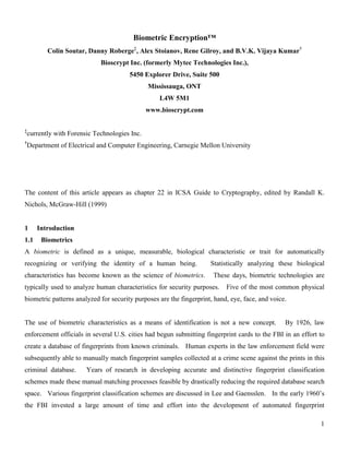
An overview of the processes of enrollment and verification is stated below, with reference to figures 22-1
and 22-2, respectively.
c0(x)
•
•
•
Hstored (u)
Bioscrypt
k0 (N-bit key)
id0
(identification code)
Link
algorithm
Stage E-1
Stage
E-3
Stage E-2
Random
Array
Lookup
tableImage
processing
Encrypt
Hash
S bits of
Hstored (u)
Figure 22- 1 Overview of the enrollment process for Biometric Encryption
Enrollment:
E-1: Image Processing
Combine a series of input fingerprint images with a random (phase) array to create two output arrays:
Hstored(u) and c0(x).
E-2: Key linking
Link a cryptographic key, k0, to the pattern, c0(x), via the link algorithm.
E-3: Identification code creation
Create an identification code, id0, derived from the key, k0.
16. 16
c1(x)
•
•
•
Hstored (u)
Bioscrypt
k1 (N-bit key)
id1
Retrieval
algorithm
Stage V-1
Stage
V-3
Stage V-2
Lookup
table
Image
processing
Encrypt
Hash
S bits of
Hstored (u)
Compareid0
Figure 22- 2 Overview of the verification process for Biometric Encryption
Verification:
V-1: Image Processing
Combine Hstored(u), from the Bioscrypt, with a new series of input fingerprint images to create an
output pattern, c1(x).
V-2: Key Retrieval
Extract a key, k1, from c1(x) using the retrieval algorithm.
V-3: Key Validation
Validate k1 by creating a new identification code, id1, and comparing it with id0.
The processes of enrollment and verification are generally symmetric with respect to the linking and
retrieving of the digital key. Previously in this chapter, details were provided on the creation of c(x), i.e.
stages E-1 and V-1. This section now completes the description of the Biometric Encryption algorithm by
discussing the link and retrieval algorithms (stages E-2 and V-2) as well as the identification code creation
and key validation processes (stages E-3 and V-3). For the purposes of explanation, consider that all output
17. 17
arrays, c(x), are 128×128 complex-valued arrays, and that the cryptographic key, k0, is 128 bits in length, i.e.
N = 128 in figures 22-1 and 22-2.
3.1 Enrollment
The objective of the enrollment procedure is to link an arbitrary N-bit key to the user’s fingerprint and create
the user's Bioscrypt.
With reference to figure 22-1, the three inputs required for the enrollment procedure are: a set of the
legitimate user's fingerprint images, a randomly generated phase-only array, R(u), and an N-bit cryptographic
key, k0. R(u) is generated using a random number generator (RNG). The key, k0, may be an existing key
that is input to the Biometric Encryption algorithm, or it may be generated by the RNG. Note that both the
key, k0, and the random phase array, R(u), are completely independent from the biometric images.
3.1.1 E-1: Image processing
•
•
•
FT-1
• •
( )u0Ai
e
φ− ( )uRi
e φ ( )x0c
( )x1
0f ( )xT
0f
( )
( )u1
u
0
2
0
D
A
α−+α
( )u0A
•
FT
Random
Number
Generator
Bioscrypt
( )ustoredH
( )u0A ( )u0Ai
e
φ
Figure 22- 3 Image processing used in enrollment
18. 18
With reference to figure 22-3, the objective of this stage of enrollment is to generate an output pattern, c0(x),
to be passed to stage E-2, as well as to generate the stored filter function, Hstored(u). As discussed previously
in this chapter, T fingerprint images are acquired from the system user (typically, 4 to 6 images are used).
Fourier transforms are then performed on the images and the terms A0(u) and D0(u) are calculated using
equations 22-7 and 22-8, respectively. The phase term,
( )ui A
e 0
φ
, is extracted from A0(u) and its complex
conjugate,
( )ui A
e 0
φ−
, is used in conjunction with R(u) to calculate Hstored(u) according to equation 22-20.
The output pattern, c0(x), is then calculated via equation 22-16. Note that c0(x) is a 128×128 complex-
valued array, while Hstored(u) is a 128×128 phase-only array. Hstored(u), is then stored as part of the
Bioscrypt, and c0(x) is passed to stage E-2 of enrollment.
3.1.2 E-2: Link algorithm
The link algorithm is responsible for linking the output pattern, c0(x), with an N-bit key, k0. Through this
linking process a lookup table will be created and stored in the Bioscrypt for use in key retrieval during
verification.
An important consideration for this process is that the output pattern obtained during enrollment, c0(x), and
the pattern obtained during verification, c1(x), will differ to a certain extent. These differences are due to
changes in moisture content of the user's finger, positioning of the finger on the image capture device, etc.
To accommodate these differences, some redundancy must be incorporated into the enrollment process.
There are various methods for linking k0 with c0(x), some of which may incorporate the use of error
correcting codes. One particular method using a simple repetitive code is outlined next.
19. 19
Binarize
Bioscrypt
k0
x
y
0 1 1 · · · 1 1
Binarized
enrollment
template
· · ·
Lookup table
( x,y )
( )x0c
Figure 22- 4 Key link algorithm
With reference to figure 22-4, the link algorithm comprises the selection of a portion of c0(x), a binarization
process, and the selection of L values to represent each key bit. The central 64x64 portion of c0(x) is
extracted. This extraction is to provide translation invariance during subsequent verification attempts. Next,
the real and imaginary components of the extracted portion are concatenated to form an enrollment template
of dimension 128×64, i.e. an array with 128 columns and 64 rows. For example, if the element a+bi appears
at position (x, y) of the 64×64 portion of c0(x), then, in the enrollment template, element a will appear at
position (x, y) and element b will appear at position (x+64, y). This concatenation process converts a 64×64
complex-valued array into a 128×64 real-valued array. The enrollment template now contains 8192 real
values, d, derived from either the real or imaginary components, a or b, respectively. Each value of the
enrollment template is then binarized with respect to 0.0, i.e.:
0.0dif0d
0.0dif1d
<→
≥→
This forms a 128×64 binarized enrollment template, which will be used to link with k0.
20. 20
Suppose that the first bit of k0 is 0. Choose L locations from the binarized enrollment template whose
element values are all 0. These locations are then stored as the first column of the lookup table. This
process is continued for all other bits of the key. Each location in the binarized enrollment template can be
used to represent only one key bit. The lookup table now consists of 128 columns with each column
containing L locations in the binarized enrollment template.
Certain constraints on the L values chosen must be observed to create a satisfactory lookup table (Soutar et
al, Biometric Encryption™ - Enrollment and Verification Procedures). These are summarized below:
- L should be greater than one, to provide redundancy in the subsequent retrieval of the key.
- The value of L should be limited to ensure a sufficient number of values exist in the binarized
enrollment template to link with extreme key permutations (i.e. a key containing significantly more ones
than zeroes, or zeroes than ones).
- The selection of the L constituent bits for each key bit should be chosen to minimize the resulting
probability of error in each key bit.
- L should be an odd number so that a majority rule decision process can be used during verification.
3.1.3 E-3: Identification code creation
A requirement of the Biometric Encryption algorithm is that an incorrect key should be produced when an
attacker uses the system with another user’s Bioscrypt. In fact, it is convenient to further constrain the
system such that an incorrect key is never released from the algorithm, but instead a verification failed
message is passed to the cryptographic system. This will avoid the cryptographic system making wasteful
attempts at decryption using an incorrect key. Therefore, a key validation scheme is required for the
process. Obviously the key, k0, itself cannot be stored in the Bioscrypt for comparison with the key
generated at verification. Instead, a combination of standard encryption and hashing algorithms is used to
produce a derived identification code, id0. During verification, a corresponding identification code will be
similarly derived from the retrieved key, k1. Comparing the identification code created during verification
with that created during enrollment allows the system to determine if the key retrieved during verification is
correct.
The method used for key validation is as follows. Using the input N-bit key, k0, as an encryption key,
encrypt S bits of data. Next, hash the encrypted text using a one-way hash function to create an
identification code, id0. Store this identification code in the Bioscrypt.
21. 21
The S bits, to be encrypted, can be any S bits that will be available at both enrollment and verification.
Also, these S bits should be different for each user in order to provide the key validation procedure with
maximal security, see Schneier. Given these constraints, we use S bits from the stored filter function,
Hstored(u), as it is available during both the enrollment and verification procedures. Also, because Hstored(u)
is the product of fingerprint information and a random array, it will be distinct for each user. Therefore, we
use the first S bits of Hstored(u) as input data to the encryption algorithm.
The choice of encryption algorithm and hash function is independent of the Biometric Encryption process.
These algorithms are required simply for creation of the identification code, and the main concern in the
choice of these algorithms is that they are secure. Good examples to use are Triple-DES as the encryption
engine and SHA-1 as the hash function (Schneier).
The lookup table and id0 are now appended to Hstored(u) to complete construction of the Bioscrypt, which can
be stored on any conventional storage medium.
3.2 Verification
The objective of the verification procedure is the successful retrieval of the N-bit key for a legitimate user.
With reference to figure 22-2, a set of biometric images is acquired from the system user and combined with
Hstored(u), the lookup table, and id0, from the Bioscrypt, to retrieve and check the validity of an N-bit key. If
this key is found to be correct, it will be passed on to the cryptographic system.
22. 22
3.2.1 V-1: Image processing
( )
( )u1
u
1
2
1
D
A
α−+α
( )x1c
( )xT
1f( )x1
1f
Bioscrypt
( )ustoredH
FT-1
•
•
•
FT
•
( )u1A
•( )u1A
( )u1Ai
e
φ
Figure 22- 5 Image processing used in verification
With reference to figure 22-5, it is observed that the image processing stage of verification is very similar to
the corresponding stage of enrollment. As in enrollment, T fingerprint images are acquired from the system
user. Fourier transforms are performed on the images and the terms A1(u) and D1(u) are calculated. Using
Hstored(u) retrieved from the Bioscrypt, the output pattern, c1(x), is calculated according to equation 22-19,
and is then passed to stage V-2 of the verification procedure to retrieve the N-bit cryptographic key.
The verification pattern, c1(x), will be used to retrieve the cryptographic key. Clearly, the similarity of the
output patterns, c1(x) and c0(x), significantly affects the discrimination capabilities of the system. It is
therefore interesting to compare the generation of c1(x) and c0(x) for legitimate users and attackers, and to
understand how this affects the discrimination of the system.
23. 23
Consider equations 22-15 and 22-18 which define the enrollment and verification output patterns,
respectively:
( ) ( ) ( ) ( )
( ) ( )
( ) ( ) ï
ý
ü
ïî
ï
í
ì
úû
ù
êë
é•
α−+α
•= φφ−φ− uu
0
2
0u
0
1
0
00
u1u
u
ux RAA iii
ee
DP
A
eAFTc
( ) ( ) ( ) ( )
( ) ( )
( ) ( ) ï
ý
ü
ïî
ï
í
ì
úû
ù
êë
é•
α−+α
•= φφ−φ− uu
1
2
1u
1
1
1
01
u1u
u
ux RAA iii
ee
DP
A
eAFTc
where
( ) ( )ù
êë
é φφ− uu0 RA ii
ee defines the stored filter function, Hstored(u), according to equation 22-20. Recall
that the terms A0(u), D0(u) and A1(u), D1(u) are calculated using the input fingerprint images acquired during
enrollment and verification, respectively.
The magnitude terms in equation 22-15, ( )u0A and ( )u0D are derived from the user’s fingerprint. The
phase arrays from the user’s fingerprints cancel, leaving ( )uRi
e φ
, the random phase array, as the sole phase
contribution to the output, c0(x). The magnitude terms moderate the contribution of the various phase
values to produce c0(x) so that areas in the FT which were more consistent across the enrollment training set
are given more weight.
Now consider a c1(x) pattern generated during verification by a legitimate user and an attacker:
Legitimate user:
A1(x) ≈ A0(x), D1(x) ≈ D0(x), and
( ) ( )
1
uu 01 ť
φ−φ AA ii
ee .
The magnitude information is thus similar to that used during enrollment to generate c0(x), and the phase
information,
( )u1Ai
e
φ
, from the user’s fingerprints during verification essentially cancels out the phase
information,
( )u0Ai
e
φ−
, from the user’s fingerprints during enrollment. This leaves ( )uRi
e φ
, the random
phase array, as the only phase contribution to c1(x), as required.
Attacker:
A1(x) ≠ A0(x), D1(x) ≠ D0(x), and
( ) ( )
1
uu 01 ≠•
φ−φ AA ii
ee .
24. 24
The magnitude information from the attacker’s fingerprints is not equivalent to that derived from the
legitimate user. Therefore, the weighting of the contribution of the phase values is not properly
moderated. Furthermore, the phase information derived from the attacker’s fingerprints does not
cancel the enrollment phase information which was implicitly stored in Hstored(u). Thus, both the
magnitude and phase terms derived from the attacker’s fingerprint affect the generation of c1(x),
producing a pattern that is significantly different from the legitimate user’s c0(x) pattern. Thus, the key
retrieved from this pattern will not match the key linked to c0(x) during legitimate user enrollment.
3.2.2 V-2: Retrieval algorithm
The retrieval algorithm is responsible for retrieving a key from the verification output pattern, c1(x). The
following section describes the steps required to retrieve an N-bit key that was linked with c0(x) using the
link algorithm described earlier.
Binarize
Lookup tableBioscrypt
0 1 1
0
1
0
0
0
1
1
1
1
1
1
1
0
1
0
Decision by majority
( )x1c
k1
1
0
1
1
0
1
Binarized
verification
template
Figure 22- 6 Key retrieval algorithm
Retrieval algorithm (with reference to figure 22-6):
1. Extract the central 64×64 portion of c1(x).
25. 25
2. Concatenate the real and imaginary parts, as in the enrollment stage E-2, to create a verification template
of dimension 128×64. Binarize each value, as in E-2, to create a binarized verification template (the
equivalent of the binarized enrollment template).
3. Use the lookup table to extract the constituent bits of the binarized verification template that are required
for the key. Define k1 as an N-element vector. For the nth
element of k1, sum the L bits of the binarized
verification template whose indices are specified by the nth
column of the lookup table. The nth
element
of k1 is set to 1 if the sum of these bits is greater than L/2, and it is set to 0 otherwise. In other words, a
decision by majority is used to assign the parity of the nth
bit of k1.
4. Determine the validity of the retrieved key. This process is described in the following section on
verification stage V-3.
5. If k1 is found to be the correct key, release it into the system. If k1 is found to be incorrect, return to
c1(x) and extract a 64×64 portion of c1(x) that is offset from the center by one pixel. Continue to repeat
steps 2 to 5 of the retrieval algorithm with all portions of c1(x) that are one pixel offset from the center,
then continue with all portions that are two pixels offset from the center, and so on, up to approximately
sixteen pixel offsets. If at any point the key retrieved is found to be correct, cease the algorithm and
release k1. If the key is found to be incorrect for all pixel offsets, release a verification failed message.
Note that step 5 of the key retrieval algorithm is required to accommodate relative translations of the input
fingerprints between enrollment and verification. We find that, in general, a search of one quarter of the
input aperture, or ±16 pixels in an array of dimension 128×128, is sufficient.
3.2.3 V-3: Key validation
Step 4 of the retrieval algorithm requires that a key, k1, be checked for validity. This key should be released
only if it precisely matches k0, the key linked to the output pattern during enrollment. To check the validity
of k1, we calculate an identification code, id1, and compare it with the stored id0. The identification code,
id1, is calculated the same way as id0 was during enrollment stage E-3, i.e. using k1 as an encryption key,
encrypt the same S bits of the stored filter function, then hash the encrypted text to produce id1. The
identification code, id1, is then compared with id0. If id1 = id0, then k1 = k0, with high probability
(Schneier), and k1 can be released to the cryptographic system. If id1 ≠ id0, then k1 ≠ k0 and either a
verification failed message is released, or the retrieval algorithm continues with the next pixel offset of c1(x).
26. 26
4 Biometric Encryption using other biometric templates
Although the Biometric Encryption algorithm was developed primarily for use with image-based biometric
templates, the process can also be applied to other biometric templates. This can be achieved simply by
representing the non image-based biometric template as an image array. For example, a minutiae-based
fingerprint template can be represented as an image array by embedding a code referring to each minutiae
type at the appropriate location in a two-dimensional array, thereby creating a map of the minutiae points.
This array can then be input to the Biometric Encryption algorithm, as described above for fingerprint
images. Using a minutiae-based rather than an image-based template may have the added advantage of
producing a rotation invariant system, assuming the original minutiae template contained information about
the relative orientation of the minutiae.
For some other biometric types, different considerations may modify the algorithm. For example, images of
the iris or retina can easily be aligned using the center of the eye’s pupil as a reference point. Thus, for these
types of images, the Biometric Encryption process is not required to be translation invariant. Therefore,
transforms other than the Fourier transform may be appropriate, such as the Gabor transform, which was
originally used in the algorithm for iris identification developed by Daugman. Also, the distortion tolerance
requirements of the filter function may be relaxed for biometrics other than fingerprints. The majority of the
distortions present in fingerprint images is due to the skin deforming on contact with a glass or metal surface.
For other biometrics, such as the iris or retina, there typically is no direct contact between the biometric and
the system. Therefore, less distortion will be present in these biometric images, and the distortion tolerance
of the filter can be decreased either by adjusting α in equation 22-11, or by completely removing the
magnitude terms in equations 22-15 and 22-18. This will typically make the system more secure by
improving the discrimination capabilities of the system.
27. 27
5 Conclusions
Biometric Encryption is an algorithm for the linking and retrieval of digital keys, which can be used as a
method for the secure management of cryptographic keys. The cryptographic key is generated
independently from the Biometric Encryption algorithm and can be updated periodically via a re-enrollment
procedure. The convenience and security provided by Biometric Encryption will undoubtedly help to
promote more widespread use of cryptographic systems.
Biometric Encryption and Bioscrypt are registered trademarks of Mytec Technologies Inc.
6 References
[1] Albert Bodo, “Method for producing a digital signature with aid of a biometric feature”, German
patent DE 42 43 908 A1, (1994).
[2] J. Daugman, “High confidence visual recognition of persons by a test of statistical independence”,
IEEE Trans. on Pattern Analysis and Machine Intelligence 15, 1148-1161, (1993)
[3] J.W. Goodman, Introduction to Fourier Optics, McGraw-Hill, (1968).
[4] W.B. Hahn, Jr., and K.A. Bauchert, “Optical correlation algorithm development for the Transfer of
Optical Processing to Systems (TOPS) program”, Proc. SPIE 1959, 48-54, (1993).
[5] B.V.K. Vijaya Kumar, “Tutorial survey of composite filter designs for optical correlators,” Applied
Optics, 31, 4773-4801, (1992)
[6] B.V.K. Vijaya Kumar and L. Hassebrook, “Performance Measures for Correlation Filters”, Applied
Optics, 29, 2997-3006, (1990).
[7] H.C. Lee and R.E. Gaensslen, Eds., Advances in Fingerprint Technology, CRC Press, New York:
Elsevier, (1991).
[8] Abhijit Mahalanobis, B.V.K. Vijaya Kumar and David Casasent, “Minimum average correlation
energy filters,” Appl. Opt. 26, 3633-3640, (1987).
[9] Danny Roberge, Colin Soutar and B.V.K. Vijaya Kumar, “Optimal correlation filter for fingerprint
verification”, Proc. SPIE 3386, 123-133, (1998).
[10] Ph. Réfrégier, “Optimal trade-off filters for noise robustness, sharpness of the correlation peak, and
Horner efficiency,” Opt. Lett. 16, 829-831, (1991).
[11] Bruce Schneier, Applied Cryptography, 2nd
Ed., John Wiley & Sons, Inc., New York, (1996).
[12] Colin Soutar, Danny Roberge, Alex Stoianov, Rene Gilroy, and B.V.K. Vijaya Kumar, “Biometric
Encryption™ using image processing”, Proc. SPIE 3314, 178-188, (1998).
28. 28
[13] Colin Soutar, Danny Roberge, Alex Stoianov, Rene Gilroy, and B.V.K. Vijaya Kumar, "Biometric
Encryption™ - Enrollment and Verification Procedures", Proc. SPIE 3386, 24-35, (1998).
[14] E.G. Steward, Fourier Optics: an introduction, Ellis Horwood Limited, (1983).
[15] D. Stinson, Cryptography: theory and practice, CRC Press Inc., Boca Raton, (1995).
[16] Alex Stoianov, Colin Soutar, and Al Graham, “High-speed fingerprint verification using an optical
correlator,” Proc. SPIE 3386, 242-252, (1998).
[17] A. VanderLugt, Optical Signal Processing, John Wiley & Sons, Inc., (1992).