SlideShare a Scribd company logo
1 of 33
Download to read offline
50
567
69
557
69
567
50
2100
450
600
550
450
720
400
449
A
A
B
B
C
C D
D
E
E
1900
352
Section D-D
402
FINISH TOLERANCE MATERIAL PROJECTION Drawn by: Daniel Cash Scale: 1: 20 and section @ 1:10
Drawing title: Orthographics
Sheet no.: 1 of 3
Date: 04.11.21
Project name:
DAA boardroom table
All dimensions in mm
Clear high gloss lacquer
First angle projection
+-2mm Mahogany
50
20
50
44
21
50
55
10
10
26
100
69
Section A-A
26
44
5
20
65
694
25
297 78
400
352
44
50
44
44
All joint consist of 10mm x 50mm dominos.
Fielded panel consist of MDF substrate lipped
with 35mm x 18mm solid mahogany lipping
and veneered with mahogany . 5mm shodow
gap between frame and panel. All panel
grooves measure 8mm width by 10mm
depth.21mm x 60mm brace at front of frame
joins the two sides together with a dovetail of a
1:8 ratio.
FINISH TOLERANCE MATERIAL PROJECTION Drawn by: Daniel Cash Scale: 1: 5
Drawing title: sections 1
Sheet no.: 2 of 3
Date: 04.11.21
Project name:
DAA boardroom table
All dimensions in mm
High gloss clear
lacquer
+-2mm Mahogany
First angle projection
at A3
Section C-C
21
44
5
20
16
40
69
50
2mm mahogany edging
26
Section E-E
Meeting point of small and big table. See
appendix part 1 for image of clips used to join
tables together.
Joining clip
186
550
10
R13
Section B-B
FINISH TOLERANCE MATERIAL PROJECTION Drawn by: Daniel Cash Scale: 1: 2 and 1:5
Drawing title: sections 2
Sheet no.: 3 of 3
Date: 04.11.21
Project name:
DAA boardroom table
All dimensions in mm
High gloss clear
lacquer
+-2mm Mahogany
First angle projection
Elevation
End View
Plan
800
300
800
750
900
155
130
150
819
900
Piece Length Width Thickness Quantity Material
Base:
Front leg 1000 40 40 2 Walnut
Back leg 1000 40 40 2 Walnut
Front Apron 900 70 21 2 Walnut
Side Apron 300 70 21 2 Walnut
Stretcher 900 30 30 1 Walnut
Side stretcher 300 30 20 2 Walnut
Inlay 2400 4 1 1 Ebony + maple
Cab:
Side 850 260 21 2 Walnut
Top 800 300 21 1 Walnut
Bottom 758 295 18 1 Ply
Large shelf 758 245 18 1 Ply
Small shelf 370 199 18 2 Ply
Shelf edging 3500 5 18 1 Walnut
Veneer - Shelf 1.106 m² 0.5 1 Walnut
Veneer - Back panel 0.49 m² 0.5 1 Maple
Veneer - Door panel 0.8 m² 0.5 1 Walnut
Partition 709 250 18 1 Ply
Drawer front 380 96 30 2 Walnut
Drawer side 212 96 10 4 Walnut
Drawer back 316 73 10 2 Walnut
Drawer base 306 237 4 2 Ply
Filler 100 50 21 2 Walnut
Guides 194 50 18 4 Ply
Back panel 694 644 4 1 Ply
Back stile 800 48 15 2 Walnut
Back rail 800 48 15 2 Walnut
Door rail 400 66 40 4 Walnut
Meeting stile left 750 46 31 1 Walnut
Meeting stile right 750 40 31 1 Walnut
Outside stile 750 40 40 2 walnut
Door panel 643 315 4 2 Ply
Hardware:
Knife hinges x x x 4 Brass
Door push caps x x x 2 Plastic
Drawer push caps x x x 2 Plastic
Binding screws x x x 4 Brass
Art. no. 362.10.803 x 4
Art. no. 245.18.500 x 2
Art. no. 356.05.071 x 4
Article number N/A x 4
FINISH TOLERANCE MATERIAL PROJECTION Drawn by: DC Scale: 1: 10
Drawing title: Cover page
Sheet no.: 1 of 8
Date: 09.12.21
Project name:
Capstone
All dimensions in mm
TBD
First angle projection
+-2MM
at A3
Walnut
Maple
Ebony
30 30
900
10
50
90
50
160
20
140
40
A
A
B
B
C C
Elevation End view
Plan
819 210
160
50
30
210
759
FINISH TOLERANCE MATERIAL PROJECTION Drawn by: DC Scale: 1: 5
Drawing title: Base orthographics
Sheet no.: 2 of 8
Date: 09.12.21
Project name:
Capstone
All dimensions in mm
First angle projection
at A3
TBD +-2MM Walnut
Maple
Ebony
Section C-C
10
70
40
Maple wedges
20
5
30
20
70
70
Section A-A
Inlay banding
Section B-B
30
30
21
15
10
30
150
FINISH TOLERANCE MATERIAL PROJECTION Drawn by: DC Scale: 1: 5 and 1: 2
Drawing title: Base sections
Sheet no.: 3 of 8
Date: 09.12.21
Project name:
Capstone
All dimensions in mm
TBD +-2mm Walnut
Maple
Ebony First angle projection
at A3
850
800
250
300
21
21
30
21
25
10
50
D D
E E
Elevation
Plan
End view
FINISH TOLERANCE MATERIAL PROJECTION Drawn by: DC Scale: 1: 5
Drawing title: Cabinet with doors
Sheet no.: 4 of 8
Date: 09.12.21
Project name:
Capstone
All dimensions in mm
TBD
First angle projection
+-2mm
at A3
Walnut
Maple
50
250
100
18
100
21
21
758
0
18
800
370
Elevation
Plan
F
F
7
8mm x 30mm domino
184
184
204
250
100
4mm Walnut edging
48
631
48
Detail 3
96
4mm Walnut edging
Section F-F
FINISH TOLERANCE MATERIAL PROJECTION Drawn by: DC Scale: 1: 5
Drawing title: Cabinet with no doors
Sheet no.: 5 of 8
Date: 09.12.21
Project name:
Capstone
All dimensions in mm
TBD
First angle projection
+-2mm
at A3
Walnut
Maple
50
18
Solid walnut
Walnut veneered plywood
20
28
35
Back panel in 8mm x 8mm groove
Section D-D
Detail 1
377
250
5
Section E-E
Detail 2
11
4
40
8 8mm x 4mm groove
10
21
40
8
13
11 4
8
6
FINISH TOLERANCE MATERIAL PROJECTION Drawn by: DC Scale: 1: 5 and 1:2
Drawing title: Cabinet sections
Sheet no.: 6 of 8
Date: 09.12.21
Project name:
Capstone
All dimensions in mm
TBD
First angle projection
+-2mm
at A3
Walnut
Maple
Detail 1
Detail 3
G G
383
707
40
40
24
8mm x 5mm panel groove
Left door elevation
Plan
Section G-G
8 6mm x 15mm rebate
64
354
30
12
6
12
30
30
8
24
8
8
Left top rail elevation
Left top rail plan
Right door meeting stile Section of stiles
46
3
3
10°
1
3
5
1
2
2
1
2
6
1
4
31
12
6
12
15
2mm V groove
43
8
36 7
FINISH TOLERANCE MATERIAL PROJECTION Drawn by: DC Scale: 1: 5 and 1:2
Drawing title: Door and door sections
Sheet no.: 7 of 8
Date: 09.12.21
Project name:
Capstone
All dimensions in mm
TBD
First angle projection
+-2mm
and 1:1
Walnut
Maple
316
96
H H
Elevation
End view
Plan
Section H-H
End view
96
10
296
4mm x 5mm panel groove
5
48
67
12 237 34
12
203
33
12
306
209
237
381
84°
9
6
°
FINISH TOLERANCE MATERIAL PROJECTION Drawn by: DC Scale: 1: 5 and 1:2
Drawing title: Drawers
Sheet no.: 8 of 8
Date: 09.12.21
Project name:
Capstone
All dimensions in mm
TBD
First angle projection
+-2mm
at A3
Walnut
Maple
Drawer front in the rough
1983
2238
664
135
FINISH TOLERANCE MATERIAL PROJECTION Drawn by: Daniel Cash Scale: 1: 20
Drawing title: Entrance door
Sheet no.: 1 of 7
Date: 11.11.21
Project name:
Double margin door
All dimensions in mm
TBD
First angle projection
+-2mm Iroko
All work to be carried out in compliance with:
TGD part M
3.1.2.1
(a) the clear opening width of at least one point of access should be a minimum of 900
mm. The access route, leading from this, should maintain a clear width of at least 900 mm and
have a firm and even surface, which is suitable for people using wheelchairs or other mobility
aids and reduces the risk of slipping
3.1.2.2 Level access route
The dwelling should be designed, within the overall constraints of space, so that the difference
in level between the entrance to the dwelling and the dwelling plots point of access is
minimised. A level approach route accommodates the widest range of abilities
3.2.2 Accessible entrance
(a) there should be a clear level area at least 1200 mm wide and at least 1200 mm deep
in front of every accessible entrance
(b) the entrance should be provided with a level entry i.e. with maximum threshold height
of 15 mm with exposed edges chamfered or pencil rounded;
(c) the minimum effective clear opening width of the entrance door should be 800 mm
TGD part D
1.2 Resistance to moisture
Where any material is likely to be adversely affected by condensation, by moisture from the
ground or by airborne moisture such as rain or snow:
(a) the construction should prevent the passage of moisture to the material, or
(b) the material should be treated or otherwise protected from moisture
1.5 Glazing
Any unguarded glazing, in critical locations in doors and door side panels, at low level in
walls and partitions should be safety glazing in accordance with the recommendations of BS
6262
1.6 Letter plates
Letter plates should conform to I.S. EN 13724: 2013, and should be positioned in
accordance with Diagram 2
2.1 Adequacy of workmanship
A proper standard of workmanship and the appropriate use of any material is essential to
achieving compliance with the requirements of the Regulations
Elevation
Plan
End view
A
A
135
64
Elevation Section A-A
Section B-B
B
B B
1983
2238
135
64
375 80
56
21
70
64
1188
200
507
215
64
End view 64
375 80 945 80 375
64
5mm drip groove
FINISH TOLERANCE MATERIAL PROJECTION Drawn by: Daniel Cash Scale: 1: 10
Drawing title: Door frame
Sheet no.: 2 of 7
Date: 11.11.21
Project name:
Double margin door
All dimensions in mm
TBD
First angle projection
+-2mm
at A3
Iroko
*All rebates and grooves shown measure
12mm x 60mm.
*All 45 degree chamfers measure 10mm.
Glazing to consist of double glazed 5mm clear
self cleaning toughened glass in accordance
with the recommendations of BS626, Part 4.
Any fixings and ironmongery used must consist
of non corrosive materials.
Ends of through tenons to be sealed with paint
or suitable resin adhesive, particularly tenons
in both the frame head and cill.
All work to be carried out in accordance with
Technical Guidance Document D Materials and
Workmanship, Section 2.
64
600
1983
135
560
Elevation
Plan
End view
Detail 1
B
B
64
135
60
Section B-B
536
45 45 45
52
64
60
Detail 1
35 25 30 25 20
FINISH TOLERANCE MATERIAL PROJECTION Drawn by: Daniel Cash Scale: 1: 10. Section @ 1:5. Detail @ 1:2.
Drawing title: Elliptical frame
Sheet no.: 3 of 7
Date: 11.11.21
Project name:
Double margin door
All dimensions in mm
TBD
First angle projection
+-2mm Iroko
60
963
95 100 100 95
507
754
254
2114
Folding wedge
Elevation
Plan
End view
287
60
71
56
C
C
B
D D
20
20
20
95 200
Section D-D
Detail 2
60
20
95
200
215
20
95
Section C-C
Detail 2
20
95
10
95
20
FINISH TOLERANCE MATERIAL PROJECTION Drawn by: Daniel Cash Scale: 1: 10, sections @ 1:5
Drawing title: Double margin door
Sheet no.: 4 of 7
Date: 11.11.21
Project name:
Double margin door
All dimensions in mm
TBD +-2mm Add material
information
First angle projection
Orthographics, sections and detail of double-margin door.
Meeting stiles joined with folding wedges. All grooves
measure 20mmx20mm. Detail shown @ scale 1:2.
15
12
8
15
17
5mm x 24mm weather bar
Inward opening door
with a rebate at the
front. Rebate conceals
weather bar which is
housed in a groove in
the cill. Drip groove in
rebate prevents water
traveling along the
horizontal section of
the rebate. Hardwood
weather bar, joined to
door with a tongue and
groove, further
prevents condensation
from traveling towards
the bottom of the door.
Hardcore
Hardcore
Thermal block
Infill
DPC
Insulation
Concrete
Finished floor level
Concrete
Gully
Both threshold details
are in compliance with
Technical Guidance
Documents:
Part M section
3.2.2 Accessible
entrance: (b) the
entrance should be
provided with a level
entry i.e. with maximum
threshold height of 15
mm with exposed
edges chamfered or
pencil rounded.
Part D Section
1.2 Resistance to
moisture: Where any
material is likely to be
adversely affected by
condensation, by
moisture from the
ground or by airborne
moisture such as rain
or snow:
(a) the construction
should prevent the
passage of moisture to
the material
Traditional threshold detail
FINISH TOLERANCE MATERIAL PROJECTION Drawn by: Daniel Cash Scale: 1: 2
Drawing title: Traditional threshold
Sheet no.: 5 of 7
Date: 11.11.21
Project name:
Double margin door
All dimensions in mm
TBD
First angle projection
+-2mm Iroko
15
20
Metal weather bar fixed to door
Rubber seal stopping drafts and water
Inward opening door
with weather strip
installed. Weather strip
consisting of two
independent
components fixed to
both the door and the
cill. Door must sit
20mm above cill to
accommodate weather
strip. Interlocking
rubber seals prevent
drafts and
condensation traveling
past the weather strip.
Hardcore
Hardcore
Thermal block
Infill
DPC
Insulation
Concrete
Finished floor level
Concrete
Gully
Both threshold details
are in compliance with
Technical Guidance
Documents:
Part M section
3.2.2 Accessible
entrance: (b) the
entrance should be
provided with a level
entry i.e. with maximum
threshold height of 15
mm with exposed
edges chamfered or
pencil rounded.
Part D Section
1.2 Resistance to
moisture: Where any
material is likely to be
adversely affected by
condensation, by
moisture from the
ground or by airborne
moisture such as rain
or snow:
(a) the construction
should prevent the
passage of moisture to
the material
Modern threshold detail
FINISH TOLERANCE MATERIAL PROJECTION Drawn by: Daniel Cash Scale: 1: 2
Drawing title: Modern threshold
Sheet no.: 6 of 7
Date: 11.11.21
Project name:
Double margin door
All dimensions in mm
TBD
First angle projection
+-2mm Iroko
Rise and going of stairs
Face mould template
Springing line
Springing line
Center line
Center line
Thickness of material needed
Center line
Center
Twist bevel angle
FINISH TOLERANCE MATERIAL PROJECTION Drawn by: Daniel Cash Scale: 1: 2
Drawing title: Wreath template
Sheet no.: 7 of 7
Date: 11.11.21
Project name:
Wreath template
All dimensions in mm
N/A +-0mm MDF
First angle projection
Front Elevation
Plan
Side Elevation
45
45
770
101°
960
5
1
2
550
95 883
45
883 95
2000
740
A
A
115 45
Front Elevation
Plan
Side Elevation
446
600
550
100°
15
45
1390
45
B
B
71
377
1500
Section B-B
292
71 9 71 9 71
21
Section B-B shows the jointing
method between the table top
and frame. The table legs are
joined with two stretchers with a
7mm x 5mm groove which
houses the buttons and leaves
room for seasonal movement.
600
Section A-A
4
5
9
1
100
230
45
Section A-A shows the meeting
point of the back and seat. The
rear stretcher houses the mitred
tenons, while the front stretcher
houses the stub tenons of the
seat.
FINISH TOLERANCE MATERIAL PROJECTION Drawn by: DC Scale: 1: 10
Client: Joe Soap
Sheet no.: 1 of 1
Date: 13/04/21
Project name:
Outdoor Furniture
All dimensions in mm
Teak oil
First angle projection
+- 2mm
Details: 1:5
Iroko
Table isometric
Sofa isometric
2927,5
900
100
850
50
98,5
Detail 1 shows the pitch line in dashed/dotted pink which
runs between each step. The top of the handrail is
positioned 900mm measured vertically from where the pitch
line meets the tread, in compliance to Technical Guidance
Document Part K.
Detail 2 shows the where the flight meets the upper
finished floor level. The final riser is housed in both the
newell post and wall string. The cut string tenon is joined to
the front of the newell post with a mortice and the newell
post also houses the trimmer joist to the rear where a fixing
is placed. A ramp easing handrail meets the newell post at
the same height as the guarding balustrade handrail on the
upper floor.
As per Technical Guidance Document Part K, a maximum
of 100mm is permitted between each spindel. Shown in the
drawings are 2 spindels per tread with a distance of 100mm
between them. These spindles form a set. The spacing
between each set of spindles is 98.5mm
Detail 1
Detail 2
Designed by
Student number Assignment
Module
TU732
Due date
Scale
Detail scale
Stairs
Joinery
1:10
1:50
Semester 1
14-12-20
C19720711
Daniel Cash
Detail 3
Detail 1
Detail 2
900
260
260
220
220
220
21
18
A A
Designed by
Student number Assignment
Module
TU732
Due date
Scale
Detail scale
Stairs
Joinery
1:10
1:50
Semester 1
14-12-20
C19720711
Daniel Cash
Section A-A shows both the riser and going measurements. Each riser and step is secured in place with slow
driving wedges, shown here in the blue. Each riser has a thickness of 18mm and each tread has a thickness of
21mm. Front of the second riser is positioned on the center line of the newell post. Shown on the right is detail
3. The handrail eases and levels off in line with the handrail on the upper level.
Section A-A
Detail 3
3360
2860
2
0
0
0
Designed by
Student number Assignment
Module
TU732
Due date
Scale
Detail scale
Stairs
Joinery
N/A
1:20
Semester 1
14-12-20
C19720711
Daniel Cash
Site measurements of 2.86m from finished floor level to
finished floor level and a max going of 3.25m. To comply
with Technical Guidance Document Part K, the max
permitted rise in a stairs for private use is 220mm. 2.86m
÷ 220 = 13 risers
A maximum going of 260mm per tread is permitted. 12
treads @ 260mm per tread = 3.12m which falls under the
max going of 3.25m.
As stated in the Technical Guidance Document Part K, a
stairs can have a max pitch of 42 degrees.With a rise of
220mm and a going of 260mm, trigonometry is used to
determine the pitch of the stairs to be 40.2 degrees.
The documents states that for a stairs to comply, the sum
of: 2(rise) + going = min. 550 and max. 700.
2(220) + 260 = 700.
Elevation
Kitchen Bath Bed 2
Bed 1
Lounge
En-Suite
Window A Window B
Window C
Door B
Door A
Window A
Window A Window A
1212
1800
549 549
1128
Window A finished cutting list
Piece Length(mm) Width(mm) Thickness(mm) Quantity
Top Rail 549 55 45 2
Bottom Rail 549 55 45 2
Stiles 1116 55 45 4
Mullion 1800 70 60 2
Frame head 1800 70 60 1
Frame jamb 2112 70 60 2
Frame cill 1800 70 60 1
Section G-G
Section H-H
Elevation
G
H
G
H
Detail 4
Detail 5
Detail 6
Detail 7
Name:
Student no.:
Date:
Module: Title:
Detail scale:
Scale:
Assignment:
Daniel Cash
C19720711
26/02/21
Estimating
Estimating
1:10
N/A
Window A
1212
900
550
826
Window B finished cutting list
Piece Length(mm) Width(mm) Thickness(mm) Quantity
Vent top Rail 826 55 45 1
Vent bottom Rail 826 55 45 1
Vent stiles 550 55 45 2
Transom 900 70 60 1
Frame head 900 70 60 1
Frame jamb 1212 70 60 2
Frame cill 900 70 60 1
Elevation
Section I-I
Section J-J
I
J
I
J
Detail 8
Detail 9
Name:
Student no.:
Date:
Module: Title:
Detail scale:
Scale:
Assignment:
Daniel Cash
C19720711
26/02/21
Estimating
Estimating
1:10
N/A
Window B
912
900
524
290
863
Window C finished cutting list
Piece Length(mm) Width(mm) Thickness(mm) Quantity
Vent top Rail 826 55 45 1
Vent bottom Rail 826 55 45 1
Vent stiles 290 55 45 2
Casement top rail 826 55 45 1
Casement bottom rail 826 55 45 1
Casement stile 524 55 45 2
Transom 900 70 60 1
Frame head 900 70 60 1
Frame jamb 912 70 60 2
Frame cill 900 70 60 1
Elevation
Section K-K
Section L-L
K
L
Detail 10
K
L
Name:
Student no.:
Date:
Module: Title:
Detail scale:
Scale:
Assignment:
Daniel Cash
C19720711
26/02/21
Estimating
Estimating
1:10
N/A
Window C
70
60
55
45
20
48
12
20
50
6
21
70
60
55
45
60
70
18
60
70
18
Detail 7 on the left shows where a
casement stile meets a mullion.
The mullion also receives a
double glazed unit on the
opposite side which forms a
deadlight.
Detail 4 on the left
shows a 70mm x
60mm window jamb
with a rebate at the
front to receive the
55mm x 44mm top
rail of the casement.
Detail 5 on the left
shows the window
casement meeting
the cill. The cill is
rebated at the
bottom to receive
the concrete cill.
Detail 6 on the left
shows the vertical
section of the
window jamb and the
stile of the window
casement.
Detail 8 shows the bottom
rail of the vent light meeting
the transom.
Name:
Student no.:
Date:
Module: Title:
Detail scale:
Scale:
Assignment:
Daniel Cash
C19720711
26/02/21
Estimating
Estimating
N/A
1:2
Window details
20
50
33
15
10
48
12
10
60
55
14
55
30
30
3
21
Detail 9 above shows a deadlight glazing panel meeting a
cill.
Detail 10 above shows the meeting point of the
transom and a vent light on top and bottom.
Name:
Student no.:
Date:
Module: Title:
Detail scale:
Scale:
Assignment:
Daniel Cash
C19720711
26/02/21
Estimating
Estimating
N/A
1:2
Window details 2
900
2100
95
95
922
215
600
215
95 644 95
92 92 92
95
44
Door A finished cutting list
Piece Length(mm) Width(mm) Thickness(mm) Quantity
Top Rail 845 95 44 1
Middle rail 845 215 44 1
Bottom Rail 845 215 44 1
Stiles 2047 95 44 2
Bottom panels 632 108 44 7
Top Panels 956 108 44 7
Frame head 900 95 44 1
Frame jamb 2100 95 44 2
A
B
C
Section A-A
Section B-B
Section C-C
Elevation
Detail 1
Detail 2
A
B
C
Name:
Student no.:
Date:
Module: Title:
Detail scale:
Scale:
Assignment:
Daniel Cash
C19720711
26/02/21
Estimating
Estimating
1:10
N/A
Door A
900
2100
922
215
600
215
95 644 95
21
92 92 92
Door B finished cutting list
Piece Length(mm) Width(mm) Thickness(mm) Quantity
Top Rail 845 95 44 1
Middle rail 845 215 44 1
Bottom Rail 845 215 44 1
Stiles 2047 95 44 2
Bottom panels 632 108 44 7
Glazing bead 1600 21 44 1
Frame head 900 95 44 1
Frame jamb 2100 95 44 2
Elevation
Detail 3
Section F-F
Section E-E
Section D-D
D
E
F
D
E
F
Name:
Student no.:
Date:
Module: Title:
Detail scale:
Scale:
Assignment:
Daniel Cash
C19720711
26/02/21
Estimating
Estimating
1:10
N/A
Door B
95
44
44
29
25
20
79
47
23
Detail 1 to the left shows a 95mm x 44mm door frame with a 46mm x
15mm rebate at the front to recieve the door. The 44mm thick door is
manufactured using tongue and groove boards as shown in detail 1.
Shown below in detail 3 is the horizontal section of the 44mm x
23mm glazing bead between the door stiles. The glazing bead
receives the double glazing panel either side and is secured with
putty.
Detail 2 on the left shows the door stopped 20mm before the
finished floor line to allow for the stormguard to be fitted.
Detail 1
Detail 2
Detail 3
Name:
Student no.:
Date:
Module: Title:
Detail scale:
Scale:
Assignment:
Daniel Cash
C19720711
26/02/21
Estimating
Estimating
N/A
1:2
Door details
Shown is an alternative jointing method
between the curved stile and straight stile
to the hammerhead tenon completed in
class. The curved sections are both joined
with a loose tenon while the top of the
curved stile joins the straight stile also with
a loose tenon. These loose tenons are
sometimes called keys. The bottom of the
curved stile is jointed to the straight stile
with a bridle joint. Sometimes draw pins
are inserted here to further secure the joint
while clamping.

More Related Content

What's hot

Design Portfolio by Aaron Kaira
Design Portfolio by Aaron KairaDesign Portfolio by Aaron Kaira
Design Portfolio by Aaron KairaAaron Kaira
 
Proposed_Floorplans_Professional Practice_DS_Group-A1@50_Proposed Basement Level
Proposed_Floorplans_Professional Practice_DS_Group-A1@50_Proposed Basement LevelProposed_Floorplans_Professional Practice_DS_Group-A1@50_Proposed Basement Level
Proposed_Floorplans_Professional Practice_DS_Group-A1@50_Proposed Basement LevelJermaine Barrett
 
M3 EG BQ steel struture
M3 EG BQ steel strutureM3 EG BQ steel struture
M3 EG BQ steel strutureEst
 
M3 EG BQ metal frame door
M3 EG BQ metal frame doorM3 EG BQ metal frame door
M3 EG BQ metal frame doorEst
 
12724469 wtp-cost-estimate
12724469 wtp-cost-estimate12724469 wtp-cost-estimate
12724469 wtp-cost-estimateimaduddin91
 
Measurement II BQ
Measurement II BQMeasurement II BQ
Measurement II BQashleyyeap
 
Lucy Fortress Feeder Pillars, Galvanised Steel - Size 22
Lucy Fortress Feeder Pillars, Galvanised Steel - Size 22Lucy Fortress Feeder Pillars, Galvanised Steel - Size 22
Lucy Fortress Feeder Pillars, Galvanised Steel - Size 22Thorne & Derrick International
 
M3 EG BQ for timber panel door
M3 EG BQ for timber panel doorM3 EG BQ for timber panel door
M3 EG BQ for timber panel doorEst
 
POSHTEL SHANGHAI 09 2017 - by Sinus Effekt
POSHTEL SHANGHAI 09 2017 - by Sinus EffektPOSHTEL SHANGHAI 09 2017 - by Sinus Effekt
POSHTEL SHANGHAI 09 2017 - by Sinus EffektMorten Lund
 
Lynca Meats - Pork Factory - Meyerton - Sections
Lynca Meats - Pork Factory - Meyerton - SectionsLynca Meats - Pork Factory - Meyerton - Sections
Lynca Meats - Pork Factory - Meyerton - SectionsTrevain Bechan
 
Porta Cabin Presentation
Porta Cabin PresentationPorta Cabin Presentation
Porta Cabin Presentationamcoengg
 
CL Final Assignment Report Part B
CL Final Assignment Report Part BCL Final Assignment Report Part B
CL Final Assignment Report Part BPang Shuen
 
5) int walls finishes bq
5) int walls finishes bq5) int walls finishes bq
5) int walls finishes bqJeanne Hoo
 

What's hot (20)

Design Portfolio by Aaron Kaira
Design Portfolio by Aaron KairaDesign Portfolio by Aaron Kaira
Design Portfolio by Aaron Kaira
 
Proposed_Floorplans_Professional Practice_DS_Group-A1@50_Proposed Basement Level
Proposed_Floorplans_Professional Practice_DS_Group-A1@50_Proposed Basement LevelProposed_Floorplans_Professional Practice_DS_Group-A1@50_Proposed Basement Level
Proposed_Floorplans_Professional Practice_DS_Group-A1@50_Proposed Basement Level
 
M3 EG BQ steel struture
M3 EG BQ steel strutureM3 EG BQ steel struture
M3 EG BQ steel struture
 
M3 EG BQ metal frame door
M3 EG BQ metal frame doorM3 EG BQ metal frame door
M3 EG BQ metal frame door
 
8 months work
8 months work8 months work
8 months work
 
Lucy Zodion Feeder Pillar Catalogue
Lucy Zodion Feeder Pillar CatalogueLucy Zodion Feeder Pillar Catalogue
Lucy Zodion Feeder Pillar Catalogue
 
12724469 wtp-cost-estimate
12724469 wtp-cost-estimate12724469 wtp-cost-estimate
12724469 wtp-cost-estimate
 
Measurement II BQ
Measurement II BQMeasurement II BQ
Measurement II BQ
 
Lucy Fortress Feeder Pillars, Galvanised Steel - Size 22
Lucy Fortress Feeder Pillars, Galvanised Steel - Size 22Lucy Fortress Feeder Pillars, Galvanised Steel - Size 22
Lucy Fortress Feeder Pillars, Galvanised Steel - Size 22
 
Versaloc
VersalocVersaloc
Versaloc
 
M3 EG BQ for timber panel door
M3 EG BQ for timber panel doorM3 EG BQ for timber panel door
M3 EG BQ for timber panel door
 
BQ
BQBQ
BQ
 
005
005005
005
 
POSHTEL SHANGHAI 09 2017 - by Sinus Effekt
POSHTEL SHANGHAI 09 2017 - by Sinus EffektPOSHTEL SHANGHAI 09 2017 - by Sinus Effekt
POSHTEL SHANGHAI 09 2017 - by Sinus Effekt
 
Lynca Meats - Pork Factory - Meyerton - Sections
Lynca Meats - Pork Factory - Meyerton - SectionsLynca Meats - Pork Factory - Meyerton - Sections
Lynca Meats - Pork Factory - Meyerton - Sections
 
Porta Cabin Presentation
Porta Cabin PresentationPorta Cabin Presentation
Porta Cabin Presentation
 
001
001001
001
 
CL Final Assignment Report Part B
CL Final Assignment Report Part BCL Final Assignment Report Part B
CL Final Assignment Report Part B
 
5) int walls finishes bq
5) int walls finishes bq5) int walls finishes bq
5) int walls finishes bq
 
Bq floor
Bq floorBq floor
Bq floor
 

Similar to Design tab

Camperdown Warehouse FF&E Schedule
Camperdown Warehouse FF&E ScheduleCamperdown Warehouse FF&E Schedule
Camperdown Warehouse FF&E ScheduleLindaJaneVanhear2
 
3D Drafting Collection - Letter Size
3D Drafting Collection - Letter Size3D Drafting Collection - Letter Size
3D Drafting Collection - Letter SizeNick Taylor
 
ALYSSA MASON - PORTFOLIO - SCDC
ALYSSA MASON - PORTFOLIO - SCDCALYSSA MASON - PORTFOLIO - SCDC
ALYSSA MASON - PORTFOLIO - SCDCJonathan Mohabir
 
Leisure Centre
Leisure CentreLeisure Centre
Leisure CentreEdel Fox
 
Drafting service sample, residential house, Australia
Drafting service sample, residential house, AustraliaDrafting service sample, residential house, Australia
Drafting service sample, residential house, AustraliaAlexeyRyabchenko
 
PRODUCT BROCHURE OF DS ROOFING SYSTEMS
PRODUCT BROCHURE OF DS ROOFING SYSTEMSPRODUCT BROCHURE OF DS ROOFING SYSTEMS
PRODUCT BROCHURE OF DS ROOFING SYSTEMSDS TECH CORPORATION
 
Killeshin building it carlow
Killeshin building it carlowKilleshin building it carlow
Killeshin building it carlowTej Raj Upreti
 
Lucy Fortress Feeder Pillars - Single Door Feeder Pillars
Lucy Fortress Feeder Pillars - Single Door Feeder PillarsLucy Fortress Feeder Pillars - Single Door Feeder Pillars
Lucy Fortress Feeder Pillars - Single Door Feeder PillarsThorne & Derrick International
 
Lynca Meats - Pork Factory - Meyerton - Plan @ Floor Level 01
Lynca Meats - Pork Factory - Meyerton - Plan @ Floor Level 01Lynca Meats - Pork Factory - Meyerton - Plan @ Floor Level 01
Lynca Meats - Pork Factory - Meyerton - Plan @ Floor Level 01Trevain Bechan
 
Detail behind the proposal
Detail behind the proposalDetail behind the proposal
Detail behind the proposallauracarcano2
 
PORTFOLIO- Golnaz Abadian
PORTFOLIO- Golnaz AbadianPORTFOLIO- Golnaz Abadian
PORTFOLIO- Golnaz AbadianGolnaz Abadian
 
coba_flooring Brochure
coba_flooring Brochurecoba_flooring Brochure
coba_flooring BrochureMatthew Davies
 
Architectural Technology Project
Architectural Technology ProjectArchitectural Technology Project
Architectural Technology ProjectTomcully18
 
Doors winodws toilets
Doors winodws toiletsDoors winodws toilets
Doors winodws toiletsBhagya Silva
 
Buildings and Housings Catalogue 12.15
Buildings and Housings Catalogue 12.15Buildings and Housings Catalogue 12.15
Buildings and Housings Catalogue 12.15Chris Ponticorvo
 

Similar to Design tab (20)

Camperdown Warehouse FF&E Schedule
Camperdown Warehouse FF&E ScheduleCamperdown Warehouse FF&E Schedule
Camperdown Warehouse FF&E Schedule
 
3D Drafting Collection - Letter Size
3D Drafting Collection - Letter Size3D Drafting Collection - Letter Size
3D Drafting Collection - Letter Size
 
Stoneham
Stoneham Stoneham
Stoneham
 
ALYSSA MASON - PORTFOLIO - SCDC
ALYSSA MASON - PORTFOLIO - SCDCALYSSA MASON - PORTFOLIO - SCDC
ALYSSA MASON - PORTFOLIO - SCDC
 
Leisure Centre
Leisure CentreLeisure Centre
Leisure Centre
 
Drafting service sample, residential house, Australia
Drafting service sample, residential house, AustraliaDrafting service sample, residential house, Australia
Drafting service sample, residential house, Australia
 
JOINERY_WORK
JOINERY_WORKJOINERY_WORK
JOINERY_WORK
 
PRODUCT BROCHURE OF DS ROOFING SYSTEMS
PRODUCT BROCHURE OF DS ROOFING SYSTEMSPRODUCT BROCHURE OF DS ROOFING SYSTEMS
PRODUCT BROCHURE OF DS ROOFING SYSTEMS
 
Killeshin building it carlow
Killeshin building it carlowKilleshin building it carlow
Killeshin building it carlow
 
All drawings
All drawingsAll drawings
All drawings
 
Small House Plans & Calculations.pdf
Small House Plans & Calculations.pdfSmall House Plans & Calculations.pdf
Small House Plans & Calculations.pdf
 
Lucy Fortress Feeder Pillars - Single Door Feeder Pillars
Lucy Fortress Feeder Pillars - Single Door Feeder PillarsLucy Fortress Feeder Pillars - Single Door Feeder Pillars
Lucy Fortress Feeder Pillars - Single Door Feeder Pillars
 
Lynca Meats - Pork Factory - Meyerton - Plan @ Floor Level 01
Lynca Meats - Pork Factory - Meyerton - Plan @ Floor Level 01Lynca Meats - Pork Factory - Meyerton - Plan @ Floor Level 01
Lynca Meats - Pork Factory - Meyerton - Plan @ Floor Level 01
 
The specs of container house
The specs of container houseThe specs of container house
The specs of container house
 
Detail behind the proposal
Detail behind the proposalDetail behind the proposal
Detail behind the proposal
 
PORTFOLIO- Golnaz Abadian
PORTFOLIO- Golnaz AbadianPORTFOLIO- Golnaz Abadian
PORTFOLIO- Golnaz Abadian
 
coba_flooring Brochure
coba_flooring Brochurecoba_flooring Brochure
coba_flooring Brochure
 
Architectural Technology Project
Architectural Technology ProjectArchitectural Technology Project
Architectural Technology Project
 
Doors winodws toilets
Doors winodws toiletsDoors winodws toilets
Doors winodws toilets
 
Buildings and Housings Catalogue 12.15
Buildings and Housings Catalogue 12.15Buildings and Housings Catalogue 12.15
Buildings and Housings Catalogue 12.15
 

Recently uploaded

shot list for my tv series two steps back
shot list for my tv series two steps backshot list for my tv series two steps back
shot list for my tv series two steps back17lcow074
 
3D Printing And Designing Final Report.pdf
3D Printing And Designing Final Report.pdf3D Printing And Designing Final Report.pdf
3D Printing And Designing Final Report.pdfSwaraliBorhade
 
VIP Call Girls Service Kukatpally Hyderabad Call +91-8250192130
VIP Call Girls Service Kukatpally Hyderabad Call +91-8250192130VIP Call Girls Service Kukatpally Hyderabad Call +91-8250192130
VIP Call Girls Service Kukatpally Hyderabad Call +91-8250192130Suhani Kapoor
 
call girls in Harsh Vihar (DELHI) 🔝 >༒9953330565🔝 genuine Escort Service 🔝✔️✔️
call girls in Harsh Vihar (DELHI) 🔝 >༒9953330565🔝 genuine Escort Service 🔝✔️✔️call girls in Harsh Vihar (DELHI) 🔝 >༒9953330565🔝 genuine Escort Service 🔝✔️✔️
call girls in Harsh Vihar (DELHI) 🔝 >༒9953330565🔝 genuine Escort Service 🔝✔️✔️9953056974 Low Rate Call Girls In Saket, Delhi NCR
 
The history of music videos a level presentation
The history of music videos a level presentationThe history of music videos a level presentation
The history of music videos a level presentationamedia6
 
Call Girls In Safdarjung Enclave 24/7✡️9711147426✡️ Escorts Service
Call Girls In Safdarjung Enclave 24/7✡️9711147426✡️ Escorts ServiceCall Girls In Safdarjung Enclave 24/7✡️9711147426✡️ Escorts Service
Call Girls In Safdarjung Enclave 24/7✡️9711147426✡️ Escorts Servicejennyeacort
 
Fashion trends before and after covid.pptx
Fashion trends before and after covid.pptxFashion trends before and after covid.pptx
Fashion trends before and after covid.pptxVanshNarang19
 
VIP Call Girls Service Mehdipatnam Hyderabad Call +91-8250192130
VIP Call Girls Service Mehdipatnam Hyderabad Call +91-8250192130VIP Call Girls Service Mehdipatnam Hyderabad Call +91-8250192130
VIP Call Girls Service Mehdipatnam Hyderabad Call +91-8250192130Suhani Kapoor
 
Chapter 19_DDA_TOD Policy_First Draft 2012.pdf
Chapter 19_DDA_TOD Policy_First Draft 2012.pdfChapter 19_DDA_TOD Policy_First Draft 2012.pdf
Chapter 19_DDA_TOD Policy_First Draft 2012.pdfParomita Roy
 
Kindergarten Assessment Questions Via LessonUp
Kindergarten Assessment Questions Via LessonUpKindergarten Assessment Questions Via LessonUp
Kindergarten Assessment Questions Via LessonUpmainac1
 
Kurla Call Girls Pooja Nehwal📞 9892124323 ✅ Vashi Call Service Available Nea...
Kurla Call Girls Pooja Nehwal📞 9892124323 ✅  Vashi Call Service Available Nea...Kurla Call Girls Pooja Nehwal📞 9892124323 ✅  Vashi Call Service Available Nea...
Kurla Call Girls Pooja Nehwal📞 9892124323 ✅ Vashi Call Service Available Nea...Pooja Nehwal
 
Revit Understanding Reference Planes and Reference lines in Revit for Family ...
Revit Understanding Reference Planes and Reference lines in Revit for Family ...Revit Understanding Reference Planes and Reference lines in Revit for Family ...
Revit Understanding Reference Planes and Reference lines in Revit for Family ...Narsimha murthy
 
VIP Call Girls Service Bhagyanagar Hyderabad Call +91-8250192130
VIP Call Girls Service Bhagyanagar Hyderabad Call +91-8250192130VIP Call Girls Service Bhagyanagar Hyderabad Call +91-8250192130
VIP Call Girls Service Bhagyanagar Hyderabad Call +91-8250192130Suhani Kapoor
 
SCRIP Lua HTTP PROGRACMACION PLC WECON CA
SCRIP Lua HTTP PROGRACMACION PLC  WECON CASCRIP Lua HTTP PROGRACMACION PLC  WECON CA
SCRIP Lua HTTP PROGRACMACION PLC WECON CANestorGamez6
 
WAEC Carpentry and Joinery Past Questions
WAEC Carpentry and Joinery Past QuestionsWAEC Carpentry and Joinery Past Questions
WAEC Carpentry and Joinery Past QuestionsCharles Obaleagbon
 

Recently uploaded (20)

shot list for my tv series two steps back
shot list for my tv series two steps backshot list for my tv series two steps back
shot list for my tv series two steps back
 
Cheap Rate ➥8448380779 ▻Call Girls In Iffco Chowk Gurgaon
Cheap Rate ➥8448380779 ▻Call Girls In Iffco Chowk GurgaonCheap Rate ➥8448380779 ▻Call Girls In Iffco Chowk Gurgaon
Cheap Rate ➥8448380779 ▻Call Girls In Iffco Chowk Gurgaon
 
3D Printing And Designing Final Report.pdf
3D Printing And Designing Final Report.pdf3D Printing And Designing Final Report.pdf
3D Printing And Designing Final Report.pdf
 
VIP Call Girls Service Kukatpally Hyderabad Call +91-8250192130
VIP Call Girls Service Kukatpally Hyderabad Call +91-8250192130VIP Call Girls Service Kukatpally Hyderabad Call +91-8250192130
VIP Call Girls Service Kukatpally Hyderabad Call +91-8250192130
 
call girls in Harsh Vihar (DELHI) 🔝 >༒9953330565🔝 genuine Escort Service 🔝✔️✔️
call girls in Harsh Vihar (DELHI) 🔝 >༒9953330565🔝 genuine Escort Service 🔝✔️✔️call girls in Harsh Vihar (DELHI) 🔝 >༒9953330565🔝 genuine Escort Service 🔝✔️✔️
call girls in Harsh Vihar (DELHI) 🔝 >༒9953330565🔝 genuine Escort Service 🔝✔️✔️
 
The history of music videos a level presentation
The history of music videos a level presentationThe history of music videos a level presentation
The history of music videos a level presentation
 
Call Girls Service Mukherjee Nagar @9999965857 Delhi 🫦 No Advance VVIP 🍎 SER...
Call Girls Service Mukherjee Nagar @9999965857 Delhi 🫦 No Advance  VVIP 🍎 SER...Call Girls Service Mukherjee Nagar @9999965857 Delhi 🫦 No Advance  VVIP 🍎 SER...
Call Girls Service Mukherjee Nagar @9999965857 Delhi 🫦 No Advance VVIP 🍎 SER...
 
Call Girls In Safdarjung Enclave 24/7✡️9711147426✡️ Escorts Service
Call Girls In Safdarjung Enclave 24/7✡️9711147426✡️ Escorts ServiceCall Girls In Safdarjung Enclave 24/7✡️9711147426✡️ Escorts Service
Call Girls In Safdarjung Enclave 24/7✡️9711147426✡️ Escorts Service
 
Fashion trends before and after covid.pptx
Fashion trends before and after covid.pptxFashion trends before and after covid.pptx
Fashion trends before and after covid.pptx
 
VIP Call Girls Service Mehdipatnam Hyderabad Call +91-8250192130
VIP Call Girls Service Mehdipatnam Hyderabad Call +91-8250192130VIP Call Girls Service Mehdipatnam Hyderabad Call +91-8250192130
VIP Call Girls Service Mehdipatnam Hyderabad Call +91-8250192130
 
young call girls in Vivek Vihar🔝 9953056974 🔝 Delhi escort Service
young call girls in Vivek Vihar🔝 9953056974 🔝 Delhi escort Serviceyoung call girls in Vivek Vihar🔝 9953056974 🔝 Delhi escort Service
young call girls in Vivek Vihar🔝 9953056974 🔝 Delhi escort Service
 
Chapter 19_DDA_TOD Policy_First Draft 2012.pdf
Chapter 19_DDA_TOD Policy_First Draft 2012.pdfChapter 19_DDA_TOD Policy_First Draft 2012.pdf
Chapter 19_DDA_TOD Policy_First Draft 2012.pdf
 
Kindergarten Assessment Questions Via LessonUp
Kindergarten Assessment Questions Via LessonUpKindergarten Assessment Questions Via LessonUp
Kindergarten Assessment Questions Via LessonUp
 
Kurla Call Girls Pooja Nehwal📞 9892124323 ✅ Vashi Call Service Available Nea...
Kurla Call Girls Pooja Nehwal📞 9892124323 ✅  Vashi Call Service Available Nea...Kurla Call Girls Pooja Nehwal📞 9892124323 ✅  Vashi Call Service Available Nea...
Kurla Call Girls Pooja Nehwal📞 9892124323 ✅ Vashi Call Service Available Nea...
 
Revit Understanding Reference Planes and Reference lines in Revit for Family ...
Revit Understanding Reference Planes and Reference lines in Revit for Family ...Revit Understanding Reference Planes and Reference lines in Revit for Family ...
Revit Understanding Reference Planes and Reference lines in Revit for Family ...
 
Best VIP Call Girls Noida Sector 44 Call Me: 8448380779
Best VIP Call Girls Noida Sector 44 Call Me: 8448380779Best VIP Call Girls Noida Sector 44 Call Me: 8448380779
Best VIP Call Girls Noida Sector 44 Call Me: 8448380779
 
Cheap Rate Call girls Kalkaji 9205541914 shot 1500 night
Cheap Rate Call girls Kalkaji 9205541914 shot 1500 nightCheap Rate Call girls Kalkaji 9205541914 shot 1500 night
Cheap Rate Call girls Kalkaji 9205541914 shot 1500 night
 
VIP Call Girls Service Bhagyanagar Hyderabad Call +91-8250192130
VIP Call Girls Service Bhagyanagar Hyderabad Call +91-8250192130VIP Call Girls Service Bhagyanagar Hyderabad Call +91-8250192130
VIP Call Girls Service Bhagyanagar Hyderabad Call +91-8250192130
 
SCRIP Lua HTTP PROGRACMACION PLC WECON CA
SCRIP Lua HTTP PROGRACMACION PLC  WECON CASCRIP Lua HTTP PROGRACMACION PLC  WECON CA
SCRIP Lua HTTP PROGRACMACION PLC WECON CA
 
WAEC Carpentry and Joinery Past Questions
WAEC Carpentry and Joinery Past QuestionsWAEC Carpentry and Joinery Past Questions
WAEC Carpentry and Joinery Past Questions
 

Design tab

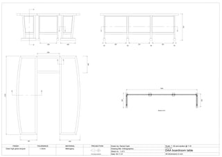
  • 1. 50 567 69 557 69 567 50 2100 450 600 550 450 720 400 449 A A B B C C D D E E 1900 352 Section D-D 402 FINISH TOLERANCE MATERIAL PROJECTION Drawn by: Daniel Cash Scale: 1: 20 and section @ 1:10 Drawing title: Orthographics Sheet no.: 1 of 3 Date: 04.11.21 Project name: DAA boardroom table All dimensions in mm Clear high gloss lacquer First angle projection +-2mm Mahogany
  • 2. 50 20 50 44 21 50 55 10 10 26 100 69 Section A-A 26 44 5 20 65 694 25 297 78 400 352 44 50 44 44 All joint consist of 10mm x 50mm dominos. Fielded panel consist of MDF substrate lipped with 35mm x 18mm solid mahogany lipping and veneered with mahogany . 5mm shodow gap between frame and panel. All panel grooves measure 8mm width by 10mm depth.21mm x 60mm brace at front of frame joins the two sides together with a dovetail of a 1:8 ratio. FINISH TOLERANCE MATERIAL PROJECTION Drawn by: Daniel Cash Scale: 1: 5 Drawing title: sections 1 Sheet no.: 2 of 3 Date: 04.11.21 Project name: DAA boardroom table All dimensions in mm High gloss clear lacquer +-2mm Mahogany First angle projection at A3
  • 3. Section C-C 21 44 5 20 16 40 69 50 2mm mahogany edging 26 Section E-E Meeting point of small and big table. See appendix part 1 for image of clips used to join tables together. Joining clip 186 550 10 R13 Section B-B FINISH TOLERANCE MATERIAL PROJECTION Drawn by: Daniel Cash Scale: 1: 2 and 1:5 Drawing title: sections 2 Sheet no.: 3 of 3 Date: 04.11.21 Project name: DAA boardroom table All dimensions in mm High gloss clear lacquer +-2mm Mahogany First angle projection
  • 4. Elevation End View Plan 800 300 800 750 900 155 130 150 819 900 Piece Length Width Thickness Quantity Material Base: Front leg 1000 40 40 2 Walnut Back leg 1000 40 40 2 Walnut Front Apron 900 70 21 2 Walnut Side Apron 300 70 21 2 Walnut Stretcher 900 30 30 1 Walnut Side stretcher 300 30 20 2 Walnut Inlay 2400 4 1 1 Ebony + maple Cab: Side 850 260 21 2 Walnut Top 800 300 21 1 Walnut Bottom 758 295 18 1 Ply Large shelf 758 245 18 1 Ply Small shelf 370 199 18 2 Ply Shelf edging 3500 5 18 1 Walnut Veneer - Shelf 1.106 m² 0.5 1 Walnut Veneer - Back panel 0.49 m² 0.5 1 Maple Veneer - Door panel 0.8 m² 0.5 1 Walnut Partition 709 250 18 1 Ply Drawer front 380 96 30 2 Walnut Drawer side 212 96 10 4 Walnut Drawer back 316 73 10 2 Walnut Drawer base 306 237 4 2 Ply Filler 100 50 21 2 Walnut Guides 194 50 18 4 Ply Back panel 694 644 4 1 Ply Back stile 800 48 15 2 Walnut Back rail 800 48 15 2 Walnut Door rail 400 66 40 4 Walnut Meeting stile left 750 46 31 1 Walnut Meeting stile right 750 40 31 1 Walnut Outside stile 750 40 40 2 walnut Door panel 643 315 4 2 Ply Hardware: Knife hinges x x x 4 Brass Door push caps x x x 2 Plastic Drawer push caps x x x 2 Plastic Binding screws x x x 4 Brass Art. no. 362.10.803 x 4 Art. no. 245.18.500 x 2 Art. no. 356.05.071 x 4 Article number N/A x 4 FINISH TOLERANCE MATERIAL PROJECTION Drawn by: DC Scale: 1: 10 Drawing title: Cover page Sheet no.: 1 of 8 Date: 09.12.21 Project name: Capstone All dimensions in mm TBD First angle projection +-2MM at A3 Walnut Maple Ebony
  • 5. 30 30 900 10 50 90 50 160 20 140 40 A A B B C C Elevation End view Plan 819 210 160 50 30 210 759 FINISH TOLERANCE MATERIAL PROJECTION Drawn by: DC Scale: 1: 5 Drawing title: Base orthographics Sheet no.: 2 of 8 Date: 09.12.21 Project name: Capstone All dimensions in mm First angle projection at A3 TBD +-2MM Walnut Maple Ebony
  • 6. Section C-C 10 70 40 Maple wedges 20 5 30 20 70 70 Section A-A Inlay banding Section B-B 30 30 21 15 10 30 150 FINISH TOLERANCE MATERIAL PROJECTION Drawn by: DC Scale: 1: 5 and 1: 2 Drawing title: Base sections Sheet no.: 3 of 8 Date: 09.12.21 Project name: Capstone All dimensions in mm TBD +-2mm Walnut Maple Ebony First angle projection at A3
  • 7. 850 800 250 300 21 21 30 21 25 10 50 D D E E Elevation Plan End view FINISH TOLERANCE MATERIAL PROJECTION Drawn by: DC Scale: 1: 5 Drawing title: Cabinet with doors Sheet no.: 4 of 8 Date: 09.12.21 Project name: Capstone All dimensions in mm TBD First angle projection +-2mm at A3 Walnut Maple
  • 8. 50 250 100 18 100 21 21 758 0 18 800 370 Elevation Plan F F 7 8mm x 30mm domino 184 184 204 250 100 4mm Walnut edging 48 631 48 Detail 3 96 4mm Walnut edging Section F-F FINISH TOLERANCE MATERIAL PROJECTION Drawn by: DC Scale: 1: 5 Drawing title: Cabinet with no doors Sheet no.: 5 of 8 Date: 09.12.21 Project name: Capstone All dimensions in mm TBD First angle projection +-2mm at A3 Walnut Maple
  • 9. 50 18 Solid walnut Walnut veneered plywood 20 28 35 Back panel in 8mm x 8mm groove Section D-D Detail 1 377 250 5 Section E-E Detail 2 11 4 40 8 8mm x 4mm groove 10 21 40 8 13 11 4 8 6 FINISH TOLERANCE MATERIAL PROJECTION Drawn by: DC Scale: 1: 5 and 1:2 Drawing title: Cabinet sections Sheet no.: 6 of 8 Date: 09.12.21 Project name: Capstone All dimensions in mm TBD First angle projection +-2mm at A3 Walnut Maple Detail 1 Detail 3
  • 10. G G 383 707 40 40 24 8mm x 5mm panel groove Left door elevation Plan Section G-G 8 6mm x 15mm rebate 64 354 30 12 6 12 30 30 8 24 8 8 Left top rail elevation Left top rail plan Right door meeting stile Section of stiles 46 3 3 10° 1 3 5 1 2 2 1 2 6 1 4 31 12 6 12 15 2mm V groove 43 8 36 7 FINISH TOLERANCE MATERIAL PROJECTION Drawn by: DC Scale: 1: 5 and 1:2 Drawing title: Door and door sections Sheet no.: 7 of 8 Date: 09.12.21 Project name: Capstone All dimensions in mm TBD First angle projection +-2mm and 1:1 Walnut Maple
  • 11. 316 96 H H Elevation End view Plan Section H-H End view 96 10 296 4mm x 5mm panel groove 5 48 67 12 237 34 12 203 33 12 306 209 237 381 84° 9 6 ° FINISH TOLERANCE MATERIAL PROJECTION Drawn by: DC Scale: 1: 5 and 1:2 Drawing title: Drawers Sheet no.: 8 of 8 Date: 09.12.21 Project name: Capstone All dimensions in mm TBD First angle projection +-2mm at A3 Walnut Maple Drawer front in the rough
  • 12. 1983 2238 664 135 FINISH TOLERANCE MATERIAL PROJECTION Drawn by: Daniel Cash Scale: 1: 20 Drawing title: Entrance door Sheet no.: 1 of 7 Date: 11.11.21 Project name: Double margin door All dimensions in mm TBD First angle projection +-2mm Iroko All work to be carried out in compliance with: TGD part M 3.1.2.1 (a) the clear opening width of at least one point of access should be a minimum of 900 mm. The access route, leading from this, should maintain a clear width of at least 900 mm and have a firm and even surface, which is suitable for people using wheelchairs or other mobility aids and reduces the risk of slipping 3.1.2.2 Level access route The dwelling should be designed, within the overall constraints of space, so that the difference in level between the entrance to the dwelling and the dwelling plots point of access is minimised. A level approach route accommodates the widest range of abilities 3.2.2 Accessible entrance (a) there should be a clear level area at least 1200 mm wide and at least 1200 mm deep in front of every accessible entrance (b) the entrance should be provided with a level entry i.e. with maximum threshold height of 15 mm with exposed edges chamfered or pencil rounded; (c) the minimum effective clear opening width of the entrance door should be 800 mm TGD part D 1.2 Resistance to moisture Where any material is likely to be adversely affected by condensation, by moisture from the ground or by airborne moisture such as rain or snow: (a) the construction should prevent the passage of moisture to the material, or (b) the material should be treated or otherwise protected from moisture 1.5 Glazing Any unguarded glazing, in critical locations in doors and door side panels, at low level in walls and partitions should be safety glazing in accordance with the recommendations of BS 6262 1.6 Letter plates Letter plates should conform to I.S. EN 13724: 2013, and should be positioned in accordance with Diagram 2 2.1 Adequacy of workmanship A proper standard of workmanship and the appropriate use of any material is essential to achieving compliance with the requirements of the Regulations Elevation Plan End view
  • 13. A A 135 64 Elevation Section A-A Section B-B B B B 1983 2238 135 64 375 80 56 21 70 64 1188 200 507 215 64 End view 64 375 80 945 80 375 64 5mm drip groove FINISH TOLERANCE MATERIAL PROJECTION Drawn by: Daniel Cash Scale: 1: 10 Drawing title: Door frame Sheet no.: 2 of 7 Date: 11.11.21 Project name: Double margin door All dimensions in mm TBD First angle projection +-2mm at A3 Iroko *All rebates and grooves shown measure 12mm x 60mm. *All 45 degree chamfers measure 10mm. Glazing to consist of double glazed 5mm clear self cleaning toughened glass in accordance with the recommendations of BS626, Part 4. Any fixings and ironmongery used must consist of non corrosive materials. Ends of through tenons to be sealed with paint or suitable resin adhesive, particularly tenons in both the frame head and cill. All work to be carried out in accordance with Technical Guidance Document D Materials and Workmanship, Section 2.
  • 14. 64 600 1983 135 560 Elevation Plan End view Detail 1 B B 64 135 60 Section B-B 536 45 45 45 52 64 60 Detail 1 35 25 30 25 20 FINISH TOLERANCE MATERIAL PROJECTION Drawn by: Daniel Cash Scale: 1: 10. Section @ 1:5. Detail @ 1:2. Drawing title: Elliptical frame Sheet no.: 3 of 7 Date: 11.11.21 Project name: Double margin door All dimensions in mm TBD First angle projection +-2mm Iroko
  • 15. 60 963 95 100 100 95 507 754 254 2114 Folding wedge Elevation Plan End view 287 60 71 56 C C B D D 20 20 20 95 200 Section D-D Detail 2 60 20 95 200 215 20 95 Section C-C Detail 2 20 95 10 95 20 FINISH TOLERANCE MATERIAL PROJECTION Drawn by: Daniel Cash Scale: 1: 10, sections @ 1:5 Drawing title: Double margin door Sheet no.: 4 of 7 Date: 11.11.21 Project name: Double margin door All dimensions in mm TBD +-2mm Add material information First angle projection Orthographics, sections and detail of double-margin door. Meeting stiles joined with folding wedges. All grooves measure 20mmx20mm. Detail shown @ scale 1:2.
  • 16. 15 12 8 15 17 5mm x 24mm weather bar Inward opening door with a rebate at the front. Rebate conceals weather bar which is housed in a groove in the cill. Drip groove in rebate prevents water traveling along the horizontal section of the rebate. Hardwood weather bar, joined to door with a tongue and groove, further prevents condensation from traveling towards the bottom of the door. Hardcore Hardcore Thermal block Infill DPC Insulation Concrete Finished floor level Concrete Gully Both threshold details are in compliance with Technical Guidance Documents: Part M section 3.2.2 Accessible entrance: (b) the entrance should be provided with a level entry i.e. with maximum threshold height of 15 mm with exposed edges chamfered or pencil rounded. Part D Section 1.2 Resistance to moisture: Where any material is likely to be adversely affected by condensation, by moisture from the ground or by airborne moisture such as rain or snow: (a) the construction should prevent the passage of moisture to the material Traditional threshold detail FINISH TOLERANCE MATERIAL PROJECTION Drawn by: Daniel Cash Scale: 1: 2 Drawing title: Traditional threshold Sheet no.: 5 of 7 Date: 11.11.21 Project name: Double margin door All dimensions in mm TBD First angle projection +-2mm Iroko
  • 17. 15 20 Metal weather bar fixed to door Rubber seal stopping drafts and water Inward opening door with weather strip installed. Weather strip consisting of two independent components fixed to both the door and the cill. Door must sit 20mm above cill to accommodate weather strip. Interlocking rubber seals prevent drafts and condensation traveling past the weather strip. Hardcore Hardcore Thermal block Infill DPC Insulation Concrete Finished floor level Concrete Gully Both threshold details are in compliance with Technical Guidance Documents: Part M section 3.2.2 Accessible entrance: (b) the entrance should be provided with a level entry i.e. with maximum threshold height of 15 mm with exposed edges chamfered or pencil rounded. Part D Section 1.2 Resistance to moisture: Where any material is likely to be adversely affected by condensation, by moisture from the ground or by airborne moisture such as rain or snow: (a) the construction should prevent the passage of moisture to the material Modern threshold detail FINISH TOLERANCE MATERIAL PROJECTION Drawn by: Daniel Cash Scale: 1: 2 Drawing title: Modern threshold Sheet no.: 6 of 7 Date: 11.11.21 Project name: Double margin door All dimensions in mm TBD First angle projection +-2mm Iroko
  • 18. Rise and going of stairs Face mould template Springing line Springing line Center line Center line Thickness of material needed Center line Center Twist bevel angle FINISH TOLERANCE MATERIAL PROJECTION Drawn by: Daniel Cash Scale: 1: 2 Drawing title: Wreath template Sheet no.: 7 of 7 Date: 11.11.21 Project name: Wreath template All dimensions in mm N/A +-0mm MDF First angle projection
  • 19. Front Elevation Plan Side Elevation 45 45 770 101° 960 5 1 2 550 95 883 45 883 95 2000 740 A A 115 45 Front Elevation Plan Side Elevation 446 600 550 100° 15 45 1390 45 B B 71 377 1500 Section B-B 292 71 9 71 9 71 21 Section B-B shows the jointing method between the table top and frame. The table legs are joined with two stretchers with a 7mm x 5mm groove which houses the buttons and leaves room for seasonal movement. 600 Section A-A 4 5 9 1 100 230 45 Section A-A shows the meeting point of the back and seat. The rear stretcher houses the mitred tenons, while the front stretcher houses the stub tenons of the seat. FINISH TOLERANCE MATERIAL PROJECTION Drawn by: DC Scale: 1: 10 Client: Joe Soap Sheet no.: 1 of 1 Date: 13/04/21 Project name: Outdoor Furniture All dimensions in mm Teak oil First angle projection +- 2mm Details: 1:5 Iroko Table isometric Sofa isometric
  • 20. 2927,5 900 100 850 50 98,5 Detail 1 shows the pitch line in dashed/dotted pink which runs between each step. The top of the handrail is positioned 900mm measured vertically from where the pitch line meets the tread, in compliance to Technical Guidance Document Part K. Detail 2 shows the where the flight meets the upper finished floor level. The final riser is housed in both the newell post and wall string. The cut string tenon is joined to the front of the newell post with a mortice and the newell post also houses the trimmer joist to the rear where a fixing is placed. A ramp easing handrail meets the newell post at the same height as the guarding balustrade handrail on the upper floor. As per Technical Guidance Document Part K, a maximum of 100mm is permitted between each spindel. Shown in the drawings are 2 spindels per tread with a distance of 100mm between them. These spindles form a set. The spacing between each set of spindles is 98.5mm Detail 1 Detail 2 Designed by Student number Assignment Module TU732 Due date Scale Detail scale Stairs Joinery 1:10 1:50 Semester 1 14-12-20 C19720711 Daniel Cash Detail 3 Detail 1 Detail 2
  • 21. 900 260 260 220 220 220 21 18 A A Designed by Student number Assignment Module TU732 Due date Scale Detail scale Stairs Joinery 1:10 1:50 Semester 1 14-12-20 C19720711 Daniel Cash Section A-A shows both the riser and going measurements. Each riser and step is secured in place with slow driving wedges, shown here in the blue. Each riser has a thickness of 18mm and each tread has a thickness of 21mm. Front of the second riser is positioned on the center line of the newell post. Shown on the right is detail 3. The handrail eases and levels off in line with the handrail on the upper level. Section A-A Detail 3
  • 22. 3360 2860 2 0 0 0 Designed by Student number Assignment Module TU732 Due date Scale Detail scale Stairs Joinery N/A 1:20 Semester 1 14-12-20 C19720711 Daniel Cash Site measurements of 2.86m from finished floor level to finished floor level and a max going of 3.25m. To comply with Technical Guidance Document Part K, the max permitted rise in a stairs for private use is 220mm. 2.86m ÷ 220 = 13 risers A maximum going of 260mm per tread is permitted. 12 treads @ 260mm per tread = 3.12m which falls under the max going of 3.25m. As stated in the Technical Guidance Document Part K, a stairs can have a max pitch of 42 degrees.With a rise of 220mm and a going of 260mm, trigonometry is used to determine the pitch of the stairs to be 40.2 degrees. The documents states that for a stairs to comply, the sum of: 2(rise) + going = min. 550 and max. 700. 2(220) + 260 = 700. Elevation
  • 23. Kitchen Bath Bed 2 Bed 1 Lounge En-Suite Window A Window B Window C Door B Door A Window A Window A Window A
  • 24. 1212 1800 549 549 1128 Window A finished cutting list Piece Length(mm) Width(mm) Thickness(mm) Quantity Top Rail 549 55 45 2 Bottom Rail 549 55 45 2 Stiles 1116 55 45 4 Mullion 1800 70 60 2 Frame head 1800 70 60 1 Frame jamb 2112 70 60 2 Frame cill 1800 70 60 1 Section G-G Section H-H Elevation G H G H Detail 4 Detail 5 Detail 6 Detail 7 Name: Student no.: Date: Module: Title: Detail scale: Scale: Assignment: Daniel Cash C19720711 26/02/21 Estimating Estimating 1:10 N/A Window A
  • 25. 1212 900 550 826 Window B finished cutting list Piece Length(mm) Width(mm) Thickness(mm) Quantity Vent top Rail 826 55 45 1 Vent bottom Rail 826 55 45 1 Vent stiles 550 55 45 2 Transom 900 70 60 1 Frame head 900 70 60 1 Frame jamb 1212 70 60 2 Frame cill 900 70 60 1 Elevation Section I-I Section J-J I J I J Detail 8 Detail 9 Name: Student no.: Date: Module: Title: Detail scale: Scale: Assignment: Daniel Cash C19720711 26/02/21 Estimating Estimating 1:10 N/A Window B
  • 26. 912 900 524 290 863 Window C finished cutting list Piece Length(mm) Width(mm) Thickness(mm) Quantity Vent top Rail 826 55 45 1 Vent bottom Rail 826 55 45 1 Vent stiles 290 55 45 2 Casement top rail 826 55 45 1 Casement bottom rail 826 55 45 1 Casement stile 524 55 45 2 Transom 900 70 60 1 Frame head 900 70 60 1 Frame jamb 912 70 60 2 Frame cill 900 70 60 1 Elevation Section K-K Section L-L K L Detail 10 K L Name: Student no.: Date: Module: Title: Detail scale: Scale: Assignment: Daniel Cash C19720711 26/02/21 Estimating Estimating 1:10 N/A Window C
  • 27. 70 60 55 45 20 48 12 20 50 6 21 70 60 55 45 60 70 18 60 70 18 Detail 7 on the left shows where a casement stile meets a mullion. The mullion also receives a double glazed unit on the opposite side which forms a deadlight. Detail 4 on the left shows a 70mm x 60mm window jamb with a rebate at the front to receive the 55mm x 44mm top rail of the casement. Detail 5 on the left shows the window casement meeting the cill. The cill is rebated at the bottom to receive the concrete cill. Detail 6 on the left shows the vertical section of the window jamb and the stile of the window casement. Detail 8 shows the bottom rail of the vent light meeting the transom. Name: Student no.: Date: Module: Title: Detail scale: Scale: Assignment: Daniel Cash C19720711 26/02/21 Estimating Estimating N/A 1:2 Window details
  • 28. 20 50 33 15 10 48 12 10 60 55 14 55 30 30 3 21 Detail 9 above shows a deadlight glazing panel meeting a cill. Detail 10 above shows the meeting point of the transom and a vent light on top and bottom. Name: Student no.: Date: Module: Title: Detail scale: Scale: Assignment: Daniel Cash C19720711 26/02/21 Estimating Estimating N/A 1:2 Window details 2
  • 29. 900 2100 95 95 922 215 600 215 95 644 95 92 92 92 95 44 Door A finished cutting list Piece Length(mm) Width(mm) Thickness(mm) Quantity Top Rail 845 95 44 1 Middle rail 845 215 44 1 Bottom Rail 845 215 44 1 Stiles 2047 95 44 2 Bottom panels 632 108 44 7 Top Panels 956 108 44 7 Frame head 900 95 44 1 Frame jamb 2100 95 44 2 A B C Section A-A Section B-B Section C-C Elevation Detail 1 Detail 2 A B C Name: Student no.: Date: Module: Title: Detail scale: Scale: Assignment: Daniel Cash C19720711 26/02/21 Estimating Estimating 1:10 N/A Door A
  • 30. 900 2100 922 215 600 215 95 644 95 21 92 92 92 Door B finished cutting list Piece Length(mm) Width(mm) Thickness(mm) Quantity Top Rail 845 95 44 1 Middle rail 845 215 44 1 Bottom Rail 845 215 44 1 Stiles 2047 95 44 2 Bottom panels 632 108 44 7 Glazing bead 1600 21 44 1 Frame head 900 95 44 1 Frame jamb 2100 95 44 2 Elevation Detail 3 Section F-F Section E-E Section D-D D E F D E F Name: Student no.: Date: Module: Title: Detail scale: Scale: Assignment: Daniel Cash C19720711 26/02/21 Estimating Estimating 1:10 N/A Door B
  • 31. 95 44 44 29 25 20 79 47 23 Detail 1 to the left shows a 95mm x 44mm door frame with a 46mm x 15mm rebate at the front to recieve the door. The 44mm thick door is manufactured using tongue and groove boards as shown in detail 1. Shown below in detail 3 is the horizontal section of the 44mm x 23mm glazing bead between the door stiles. The glazing bead receives the double glazing panel either side and is secured with putty. Detail 2 on the left shows the door stopped 20mm before the finished floor line to allow for the stormguard to be fitted. Detail 1 Detail 2 Detail 3 Name: Student no.: Date: Module: Title: Detail scale: Scale: Assignment: Daniel Cash C19720711 26/02/21 Estimating Estimating N/A 1:2 Door details
  • 32.
  • 33. Shown is an alternative jointing method between the curved stile and straight stile to the hammerhead tenon completed in class. The curved sections are both joined with a loose tenon while the top of the curved stile joins the straight stile also with a loose tenon. These loose tenons are sometimes called keys. The bottom of the curved stile is jointed to the straight stile with a bridle joint. Sometimes draw pins are inserted here to further secure the joint while clamping.