IRJET - Effect of Change in Location of Essential Elements of Saddle Supports
Design of chain drive
1. DESIGN OF CHAIN DRIVES USING MATLAB
- Cyril Mathew Samuel
Introduction
Chain Drives are used to transmit power between two
rotating shafts. They are widely used in automobile and
industrial applications. This project aims to provide
solutions for the design of chain drives using MATLAB –
technical computing software.
Figure1 : Parts of a Roller Chain Drive
Programming Methodology
Display the outputs:
Pitch , Roller diameter , Width of plates, FOS ,Centre
Distance , Number of links etc
Checking if Actual Factor of Safety is greater than
Required Factor of Safety
Finding the Power rating values of ISO Chain
Numbers
Calculation of Design Power
Calculation of service factor
Defining the inputs :
Power transmitted , Speeds of sprockets , loading ,
lubrication and rating types
In this program, the user defines the preferred maximum
number of chain strands in the drive. The program finds out
the power rating of each strand and finds out if there are
design options in that particular number of chain strand.
Once this is done, it displays all the design options in that
particular strand number. If there are no design options
available, a message is displayed and the code moves onto
check the design options in the next strand.
Sample Problem
A sample problem , taken from ‘Machine Design’ by R.S
Khurmi (Example 21.1) is solved to demonstrate the working
of the program .
Design a chain drive required to transmit 15 Kw of power .
The larger sprocket runs at 350 rpm and the smaller
sprocket runs at 1000 rpm. It operates at sixteen hours a day
.Assume drop lubrication and heavy load shock conditions.
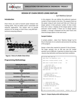
Figure 2 : Output display while defining inputs
2. The input values are entered as shown in Figure 2 , according
to the data given in the question. Of the several design
options obtained, the solution in the textbook problem is
taken for consideration, so as to compare it with the results
obtained from the program. It should be noted that the
values obtained from the program, match well with the
solution in the textbook problem .
Design Parameter Solution from
the textbook
Program
Results
Pitch (mm) 19.05 19.05
Roller Diameter (mm) 12.07 12.07
Width of inner plates
(mm)
11.68 11.68
Pitch diameter of
larger sprocket (mm)
436 430.6
Pitch Line velocity
(mm/s)
7960 7950
Actual FOS 32 30.6
Required FOS 11 12.9
Centre Distance(mm) 572 567.5
Length of chain (mm) 2096 2083
Table 1: Comparison of design solution obtained from the
program and the solved example .
Apart from the solutions displayed in Table 1 ,the program
also gives all other possible chain drive design options (listed
in Table 2).
With the different options available , the user can select a
suitable chain drive design according to his requirements ,
operating conditions and also considering economic
constraints. From Table 2 ,it can be seen that as the number
of chain drive strands increase or as the pitch increases
(considering the same number of strand ) , the actual factor
of safety increases .This means that the design is more safe.
However, it has to be noted that in a drive with more
number of strands, more material needs to be used for
manufacturing and hence this simultaneously increases the
cost of production .
Design
Parameters
Chain
Strand
= 1
Chain Strand
= 2
Chain Strand
= 3
Pitch (mm) 25.4 19 25.4 19 25.4
Roller Diameter
(mm)
15.88 12 15.8 12.07 15.8
Width between
plates (mm)
17.02 11.6 17.02 11.6 17.02
ISO chain
number
16 12 16 12 16
Breaking Load
(kN)
42.3 57.8 84.5 86.7 126.8
Pitch Diameter-
Larger Sprocket
(mm)
574.2 430 574.2 430 574.2
Pitch Line
Velocity (mm/s)
1060 7956 1060 7956 1060
Actual FOS 29.81 30.6 59 45.9 89.68
Required FOS 12.9 12.9 12 12.9 12.97
Centre Distance
(mm)
758 567.5 758 567.5 758
Number of links 109.4 109.3 109.4 109.3 109.3
Length of chain
(mm)
2780 2083 2780 2083 2780
Table 2 : All design options obtained from the program
Limitations
The program can only be used within a limited range of
transmission ratios ( 1-3 ) and speeds of pinion shaft ( 100
rpm - 1400 rpm) .The ISO chain number is also limited from
6B to 16B.
References
www.google.com
www.wikipedia.com
‘Machine Design’ – R.S Khurmi