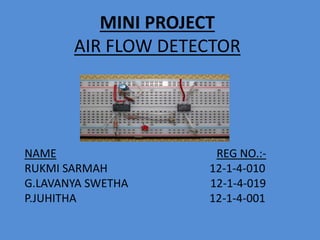
1. MINI PROJECT
AIR FLOW DETECTOR
NAME REG NO.:-
RUKMI SARMAH 12-1-4-010
G.LAVANYA SWETHA 12-1-4-019
P.JUHITHA 12-1-4-001
2. Explicit airflow detection is
essential in many applications.
High power-density electronics are
liable to overheat and self-
destruct when cooling fan failures
go unnoticed. Clean-room
air-handling systems with
undetected dirty, blocked
air filters can ruin process yield.
Laboratory fume hoods can
contain volatile solvents or toxic
reagents, making adequate air
turn-over critical to safety.
3. In these and similar scenarios, the consequences
of undetected airflow interruption can range
from the merely expensive to the frankly
dangerous. Therefore, it becomes necessary to
use some reliable means for airflow detection.
This is a design for detecting air flow. It can be
also used to check whether there is air flow in a
given space
4. BASIC IDEA
• This circuit can give a visual indication of the
rate of air flow. It can be also used to check
whether there is air flow in a given space.
• The filament of a incandescent bulb is the
sensing part of the circuit.
• A constant current source is used to slightly
heat the filament. The heated filament has a
high resistance. (H=(I^2) (RT))
5. HOW IT WORKS
When there is no air flow
the resistance of the
filament will be high.
When there is air flow
the resistance drops ,
because the moving air
will remove some of the
heat generated in the
filament.
We know that heat
generated is directly
proportional to
resistance.
6. • So, with the flow of air, resistance across the
filament varies.
• This variations in the resistance will produce
variation of voltage across the filament
(OHM’S LAW).
• These variations will be picked up by the
opamp (LM339) and the brightness of the LED
at its output will be varied proportionally to
the airflow.
8. Component required:-
S NO. TOTAL QTY DISCRIPTION
R1 1 100 Ohm 1/4W Resistor
R2 1 470 Ohm 1/4W Resistor
R3 1 10k 1/4W Resistor
R4 1 100K 1/4W Resistor
R5 1 1K 1/4W Resistor
C1 1 47uF Electrolytic Capacitor
IC1 1 7805 IC
IC2 1 LM339 IC
L1 1 filament
D1 1 LEDMISC1Board, Wire,
Sockets for ICs, etc.
9. • The filament L1 can be made by removing the
glass of a 40W incandescent bulb.
• Caution,We do not touch the filaments of
incandescent lamps by hand.
• The circuit can be powered from a 12 V DC
power supply.
• In case the filament is not available, we can
use different resistances to denote the change
in resistance across the filament.
10. GETTING FILAMENT FROM A BULB
• The glass will have to be removed from L1
without breaking the filament. We wrap the
glass in masking tape. We slowly crank down
until the glass breaks, then remove the bulb
and carefully peel back the tape. If the
filament has broken, we need another lamp.
11. IC 7805
7805 is a voltage regulator integrated circuit. It is
a member of 78xx series of fixed linear voltage
regulator ICs. The voltage source in a circuit may
have fluctuations and would not give the fixed
voltage output. The voltage regulator
IC maintains the output voltage at a constant
value. The xx in 78xx indicates the fixed output
voltage it is designed to provide. 7805 provides
+5V regulated power supply. Capacitors of
suitable values can be connected at input and
output pins depending upon the respective
voltage levels.
13. IC LM339
LM339 is a comparator IC with four inbuilt comparators. A
comparator is a simple circuit that moves signals between the
analog and digital worlds. It compares two input voltage levels
and gives digital output to indicate the larger one. The two
input pins are termed as inverting (V-) and non-inverting (V+).
The output pin goes high when voltage at V+ is greater than
that at V-, and vice versa. In common applications, one of the
pins is provided with a reference voltage and the other one
receives analog input from a sensor or any external device. If
inverting pin (V-) is set as reference, then V+ must exceed this
reference to result in high output. For inverted logic, the
reference is set at V+ pin.
15. • So as we vary the resistances, the brightness
of LED varies.
• When the resistance is high, i.e there is no air
flow, the LED doesn’t glow.
• When resistance is low i.e when air flow is
there the LED glows
• As we don’t get low resistance in the
laboratory, we use a short circuit with a wire
to denote low resistance.
18. MORE APPLICATIONS IN MEDICAL
SCIENCE
• Spirometers : A spirometer is an apparatus for
measuring the volume of air inspired and
expired by the lungs. A spirometer measures
ventilation, the movement of air into and out of
the lungs.
20. CONCLUSION
Thus, the circuit can give a visual indication of the rate of air
flow.
It can be also used to check whether there is air flow in a
given space.
The filament of an incandescent bulb is the sensing part
of the circuit.
When there is no air flow the resistance of the filament
will be high.
Thus the air flow is been detected and as an output the
LED indicates.