SlideShare a Scribd company logo
1 of 14
Download to read offline
Alex Arsenault & Seema Sud
Signal Processing: An International Journal (SPIJ), Volume (14) : Issue (1) : 2021 1
ISSN: 1985-2339, https://www.cscjournals.org/journals/SPIJ/description.php
Precise Attitude Determination Using a Hexagonal GPS Platform
Alex Arsenault alex.arsenault@aero.org
Digital Electronics and Electromagnetics Department
The Aerospace Corporation
Chantilly, VA 20151, USA
Seema Sud seema.sud@aero.org
Electronic Programs Division
The Aerospace Corporation
Chantilly, VA 20151, USA
Abstract
In this paper, a method of precise attitude determination using GPS is proposed. We use a
hexagonal antenna platform of 1 m diameter (called the wheel) and post-processing algorithms to
calculate attitude, where we focus on yaw to prove the concept. The first part of the algorithm
determines an initial absolute position using single point positioning. The second part involves
double differencing (DD) the carrier phase measurements for the received GPS signals to
determine relative positioning of the antennas on the wheel. The third part consists of Direct
Computation Method (DCM) or Implicit Least Squares (ILS) algorithms which, given sufficiently
accurate knowledge of the fixed body frame coordinates of the wheel, takes in relative positions
of all the receivers and produces the attitude. Field testing results presented in this paper will
show that an accuracy of 0.05 degrees in yaw can be achieved. The results will be compared
with a theoretical error, which is shown by Monte Carlo simulation to be < 0.001 degrees. The
improvement to the current state-of-the-art is that current methods require either very large
baselines of several meters to achieve such accuracy or provide errors in yaw that are orders of
magnitude greater.
Keywords: Carrier Phase Double Differencing, GPS, High Precision, Direct Computation
Method, Implicit Least Squares.
1. INTRODUCTION
Attitude determination is an important application of GPS. GPS attitude determination techniques
capable of delivering high precision results have been around as early as the 1980's, however
much of the previous research techniques have been dependent on the use of long distances
(referred to as baselines) between receivers to produce accurate geodetic estimates (Blewitt,
1997). The goals of this research are to develop a method of attitude determination and show that
precise attitude, i.e. < 0.05 degrees in pitch (P), roll (R), and yaw (Y), can be obtained and to
provide this using a short (<1 m) baseline. Applications include hydrographic surveying, in which
high precision ship attitude is needed for mapping the seafloor and water levels (Lu, 1995), land
surveying, and machine control.
A main issue with obtaining precision attitudes that multipath limits precision in the measured
GPS coordinates (Kos, et al., 2010). We solve this with a combination of existing GPS techniques
in conjunction with attitude computation algorithms to achieve our target accuracy. To leverage
these existing GPS algorithms, an open source software package, RTKLIB, was used to post-
process raw GPS data. We then apply post-processing algorithms, either Direct Computation
Method (DCM) or Implicit Least Squares (ILS), implemented using MatLab, to produce the pitch,
Approved for public release. OTR 2021-00195.
Alex Arsenault & Seema Sud
Signal Processing: An International Journal (SPIJ), Volume (14) : Issue (1) : 2021 2
ISSN: 1985-2339, https://www.cscjournals.org/journals/SPIJ/description.php
roll, and yaw coordinates from the RTKLIB output GPS coordinates. For simplicity, we present
only the yaw results. We will prove that yaw accuracy within the desired 0.05 degrees is feasible,
and we assume that the accuracy could be extended to pitch and roll, which are expected to be
similar. The following section will describe in more detail the antenna platform that is used to
explore this technique and will also describe the underlying theory behind the techniques applied
in our algorithm to achieve such precision. The results are demonstrated with several field tests
using a platform containing six GPS receivers.
A literature survey of current GPS-based attitude determination is provided in Raskaliyev, et al.
(2020). Most recently developed techniques use carrier phase double differencing (CPDD)
methods similar to the approach herein. The best methods were shown to employ CPDD along
with the LAMBDA method an an Extended Kalman Filter (EKF), but the accuracy of even the best
techniques is on the order of 36 - 48 cm, whereas to precision on the order of mm is required to
obtain precise pointing of < 0.05 degrees. In Farhangian, et al. (2020), the authors demonstrate
an improvement in attitude determination using an error prediction and compensation filter based
on Kalman filtering, but the accuracy in pointing is about 0.2 degrees at best.
Other authors have investigated methods using GPS for accurate pointing. In Crassidis, et al.
(2001), the authors proposed an efficient, blind combined solution using GPS and a
magnetometer, but the solution requires at least three baselines which are not coplanar.
Furthermore, this solution improves performance over GPS alone, but the attitude error is > 0.3
degrees. Past work also includes Juang, et al. (1997), who applied two new attitude
determination algorithms for resolving integer ambiguities using similar baselines to our proposed
approach, but tests showed that the error between the two algorithms was about 0.3 degrees. In
another work (Lu, 1995), the author achieved similar pointing accuracy (< 0.06 degrees) as
desired in this paper, but had to use a large baseline, i.e. a 52 m long vessel, to do so. Finally, in
Khalil (2019), the author investigated three algorithms to transform GPS based positioning
measurements from the flat surfaces on which they are computed to ground surfaces on which
they are used. Accuracies were shown to be several cm for absolute positioning.
Our goal is to show that accuracy better than 0.05 degrees can be achieved with a short baseline
of < 1 m, in multipath. We apply a combined approach using research, data collection, and data
analysis. The research is in determining a combined set of algorithms to produce the attitude
accuracy to within our desired tolerance, e.g. RTKLIB and Direct Computation Method (DCM), as
well as determining how to experimentally verify, i.e. using a novel method consisting of a
theodolite and a hexagonal GPS platform, that the proposed approach produces the desired
pointing accuracy. We collect data in the field and compute the yaw with the aforementioned
algorithms. Finally, we perform analysis on the collected data, which is verified with the
theodolite measurements; we also perform a Monte Carlo analysis to compute the theoretical
limits on yaw error as a function of the GPS position errors. Our assumptions about the multipath
environment are deductive since we did not have a way to compute the multipath profile.
An outline of the paper is as follows: The post-processing algorithm to obtain pitch, roll, and yaw
from the GPS receiver outputs is given in Section 2. A brief theoretical analysis showing the best
possible yaw as a function of GPS coordinate errors given in Section 3. The hardware setup for
the field testing is given in Section 4. Results from the field testing, showing the desired yaw
accuracy is achieved, is given in Section 5. Finally, a conclusion and discussion is provided in
Section 6.
2. PRECISION GPS AND ATTITUDE ALGORITHM
The algorithm developed is a multi-part approach for post processing raw data from our GPS
receivers using a combination of proprietary and open source receiver software. We connect to
our U-blox receivers and extract the raw measurements made by the receivers. Open source
GPS software called RTKLIB (Takasu, 2013) is then used to convert our data into the commonly
used RINEX Version 3.02 file standard. The navigation file contains information about the satellite
Alex Arsenault & Seema Sud
Signal Processing: An International Journal (SPIJ), Volume (14) : Issue (1) : 2021 3
ISSN: 1985-2339, https://www.cscjournals.org/journals/SPIJ/description.php
broadcast ephemeris while the observation file contains the specific raw measurements made by
the receiver. With the raw data files in RINEX format, we post-process the data using the RTKLIB
software suite to obtain accurate positioning, and then use DCM or ILS to obtain attitude. Fig. 1
illustrates the steps of the processing sequence.
FIGURE 1: Post-processing flow block diagram.
In the context of GPS applications, raw measurements from a receiver are referred to as
`observables'. There are two main GPS observables that were used as the basis for this
technique (and virtually all other GPS algorithms) – pseudorange and carrier phase.
Pseudorange is derived from the Coarse Acquisition (C/A) code transmitted by the GPS satellite
and is defined as the distance between the phase center of the transmitting satellite antenna and
the phase center of the receiving antenna. The carrier phase is defined as a beat frequency
between the carrier wave transmitted by the GPS satellite and the local oscillator within the GPS
receiver being used. The following sections explain the algorithm and how these observables are
used to estimate receiver position.
2.1 Single Point Solution
2.1.1 Pseudorange Observable and Model
The techniques described in the subsequent sections are used to determine relative position, so
the absolute position of at least one antenna must be solved for initially; we choose the antenna
marked Antenna 1 for this purpose, without loss of generality (see Fig. 1). Pseudorange (P) is the
observable which allows for this initial solution. The pseudorange is determined using the C/A
code, which is transmitted on the L1 carrier at a chip rate of 1,023 chips/second. A simple
equation can be written to describe the pseudorange,
(1)
where tr = time signal was received, ts = time signal was transmitted, and c = speed of light in a
vacuum. The value P, is a number which is computed by the receiver and is made available as a
`raw' measurement. In theory, P represents the range between the receiver and the satellite.
However, in reality there are many offsets and corrections that must be taken into account to
compute any reasonable position for a given receiver. When clock biases for both the satellite
and receiving clock are taken into account, this equation becomes
(2)
or
(3)
Attitude
(pitch,
roll,
yaw)
Receiver1
(reference)
Carrier Phase/
Pseudrorange
Observables
Carrier Phase Double
Differencing
Cycle Slip Detection
IntegerAmbiguity
Resolution (LAMBDA
algorithm)
Extended Kalman
Filtering
RTKLIB Carrier Based
Solution (relative)
Initial
Point
Positioning
Relative
Positions
(ECEF)
Receiver2
Receiver3
Receiver4
Receiver5
Receiver6
RTKLIB Code
SinglePoint
Solution
(absolute)
U-Blox
GPS Receivers
Direct
Computation
Method
(DCM)
or
Implicit
Least
Squares (ILS)
Convert
ECEF
to
ENU
Alex Arsenault & Seema Sud
Signal Processing: An International Journal (SPIJ), Volume (14) : Issue (1) : 2021 4
ISSN: 1985-2339, https://www.cscjournals.org/journals/SPIJ/description.php
where r = receiver clock bias, s = satellite clock bias, and = true range from receiver
tosatellite.
We follow the notation used in the literature, where superscripts and subscripts are used in
variables to denote the specific satellite and receiver combination being referenced. In this paper,
the superscript will be used to denote the satellite, and the subscript will be used to denote the
receiver. If just a subscript is used (as in the clock bias terms), then whether the subscript refers
to a satellite or receiver will be made clear from the context. Going back to Eq. (3), the term
can be replaced with a function that accounts for the Earth Centered Earth Fixed (ECEF)
coordinates of the receiver and satellite. We use the well-known Pythagorean Theorem to write
(4)
where xr, yr, zr are used to denote the ECEF coordinates of the receiver, while xs, ys, zs are used
to denote the ECEF coordinates of the satellite. Substituting Eq. (4) into Eq. (3) allows the
pseudorange observable equation to be written as:
(5)
Both satellite position and satellite clock bias are known from the navigation message, which
leaves us with four unknowns of receiver coordinates xr, yr, zr and the receiver clock bias, r. By
observing the pseudorange at regular intervals, or epochs, a system of equations can be set up
and receiver position can be solved for using a number of different mathematical methods. It is
the pseudorange observation model that is the basis for computing an initial position for our
wheel antennas. This method is described in the following section.
2.1.2 Initial Point Positioning
In the RTKLIB software that is used for post-processing our data, the following weighted least
squares method is used for estimating receiver clock bias and position (Takasu, 2013). When
using Earth Centered Earth Fixed (ECEF) coordinates to reference the location of the
receiver/satellite, a correction term is added to account for the rotation of the Earth that occurs in
between measurement periods (epochs), e. A common approximation for pseudorange that is
known to be accurate within 1 mm is
(6)
The last term in the expression is commonly referred to as the Sagnac effect (Ashby, 2004).
Another vector, , can be defined as the unit line of sight (LOS) vector from the receiver to the
satellite:
(7)
Using the following weighted least squares equation, where i is the epoch being measured, we
solve for r, the receiver position,
(8)
where
(9)
Alex Arsenault & Seema Sud
Signal Processing: An International Journal (SPIJ), Volume (14) : Issue (1) : 2021 5
ISSN: 1985-2339, https://www.cscjournals.org/journals/SPIJ/description.php
and the terms Z and I are added to account for tropospheric and ionospheric effects, respectively.
Note that for a space application, Z and I would be zero. Also,
(10)
and
(11)
is the measurement vector of pseudoranges produced by the receiver. The weight matrix, W, and
, are defined as
(12)
and
(13)
The error factor terms are defined as follows:
F
s
= satellite system error factor
Rr = code/carrier phase error ratio
a and b = carrier phase error factors
= elevation from receiver r to satellite s
eph = standard deviation of ephemeris and clock error
ion = standard deviation of ionospheric error model
trop = standard deviation of tropospheric error model
bias = standard deviation of code bias error
For the standard deviation of ephemeris and clock error, user range accuracy (URA) is used.
User range accuracy is an index value that is provided by GPS. Satellite system error factor is
defined as F
s
= 1 for GPS satellites. Code/carrier phase error ratio is defined as the ratio of
standard of pseudorange errors to carrier phase errors.
In the weighted least squares iteration, an initial r position of [000] is used. After a number of
iterations, the weighted least squares model converges to a stable value which is used as our
initial position for one receiver. This technique alone yields a solution that's accurate on the order
of a few meters. By using precise ephemeris, or by using a receiver capable of processing both
L1and L2 GPS signals, it is possible to get an even better initial position, possibly with an
accuracy of only a few centimeters (Bisnath, et al., 2018).
One of the pitfalls of the single point solution is the number of error sources such as satellite and
receiver clock bias. If less than a few centimeters of accuracy is needed, an alternative method
must be used. By using a technique that involves taking multiple differences of raw phase
measurements, many of these error sources can be either cancelled out or minimized (Blewitt,
1997). This is technique is referred to as double differencing (DD) and is explained in the
following section. Nonetheless, it provides us with a suitable initial point positioning that is
required for subsequent processing (see Fig. 1).
2.2 Carrier Phase Double Differencing (CPDD)
2.2.1 Carrier Phase Observable and Model
Since the L1 carrier frequency is 1575.42 MHz (corresponding to wavelength  = 19.05 cm), it is
capable of providing much more precise positioning information. The carrier phase observable is
Alex Arsenault & Seema Sud
Signal Processing: An International Journal (SPIJ), Volume (14) : Issue (1) : 2021 6
ISSN: 1985-2339, https://www.cscjournals.org/journals/SPIJ/description.php
typically considered and used when more precise methods of GPS positioning are needed.
Phase between the carrier of the satellite signal and the receiver's local oscillator can be
described mathematically as
(14)
where = beat phase between receiver/satellite, r = receiver local oscillator phase (in cycles),
s = satellite signal phase, and N = integer number of cycles. Time of receipt, tr, can be written as
(15)
r0 = receiver phase in cycles at start time and f0 = L1 carrier frequency. Solving Eq. (15) for r,
we obtain
(16)
Likewise, s can be rewritten as
(17)
Substituting Eqs. (16) and (17) into Eq. (14), we get
(18)
Then, by rearranging, we can write
(19)
Since we now have an expression to represent the number of cycles from satellite to receiver, we
can multiply this by wavelength, , to get an expression for the “range” (tr):
(20)
Substituting for using Eq. (19), we get
(21)
and recognizing that f0 = c,
(22)
The expression c(tr-ts) is identical to the pseudorange, while the expression (r0-s0 + N) is
defined as the carrier phase bias term, . Thus, the expression for (tr) can be written as
(23)
Adding in a term to account for clock bias between the receiver and satellite, Eq. (23) becomes
(24)
Finally, adding in terms to account for tropospheric and ionospheric delays, this becomes
(25)
Alex Arsenault & Seema Sud
Signal Processing: An International Journal (SPIJ), Volume (14) : Issue (1) : 2021 7
ISSN: 1985-2339, https://www.cscjournals.org/journals/SPIJ/description.php
For one receiver, this equation can be set up for every satellite that is in view. This is the so-
called `observation equation' which is used as the basis for the double differencing solution,
which is discussed in the next section.
2.2.2 Relative Positioning Using Carrier Phase Double Differencing
As mentioned already, one of the issues with the single point positioning methods that the error
sources such as clock bias can significantly degrade the accuracy of the result. By performing
double differencing of the carrier phase measurements between satellite and receiver pairs, these
sources of error can be greatly reduced (Blewitt, 1997). In the following discussion, we use the
conventional notation  to refer to this double differencing, where the receivers involved are
denoted by subscripts and satellites are denoted by superscripts. Fig. 2 illustrates the phase
components of a `double difference'.
FIGURE 2: Satellite and receiver pair example geometry.
Two single differences can be formed using carrier phases
(26)
and
(27)
A double difference is then formed by differencing these two single differences, i.e.
(28)
Since we have already defined individual carrier phase observable equations for each
receiver/satellite combination, we can substitute Eq. (25) for each single difference, giving
(29)
or
(30)
or
(31)
Following the same logic, we can write the single difference,  , as:
(32)
Alex Arsenault & Seema Sud
Signal Processing: An International Journal (SPIJ), Volume (14) : Issue (1) : 2021 8
ISSN: 1985-2339, https://www.cscjournals.org/journals/SPIJ/description.php
Substituting Eqs. (31) and (32) into Eq. (28), we can define the following expression for the
double difference,
(33)
or
(34)
The bias term,  , can be broken down further and simplified based on how it was defined in
Eq. (23),
(35)
(36)
(37)
(38)
(39)
The term N, although unknown, must be an integer and can be constrained as such when solving
the system of equations. In addition, for short baselines, the ionospheric and tropospheric error
terms can be effectively cancelled out. Substituting Eq. (39) into Eq. (34) and eliminating the
tropospheric and ionospheric error terms yields the following equation,
(40)
which is commonly known as the double difference observation equation. This equation is the
basis for computing the relative antennas positions which will be described in the subsequent
sections.
2.3 RTKLIB Processing
RTKLIB (Takasu, 2013) employs Extended Kalman Filtering (EKF) to estimate the position of a
receiver. The details of the EKF are beyond our scope but can be found in Takasu (2013). Using
the EKF method along with the equations noted above, we have found it is possible to estimate
receiver position to within a few millimeters. Below, we discuss the cycle slip (CS) detection and
integer ambiguity (IA) resolution that must be performed to obtain accurate position estimation.
2.3.1 Cycle Slip (CS) Detection
One common challenge of GPS algorithms is dealing with cycle slips, which is when the receiver
temporary loses lock on the signal. This can cause problems in generating output results since it
creates a discontinuity in the input data. RTKLIB uses the Loss of Lock Indicator (LLI) in the input
data stream to determine when a cycle slip has occurred. When the algorithm detects a cycle slip,
the states of the affected carrier phase bias terms are reset to their initial values so that they can
be recomputed.
2.3.2 Integer Ambiguity (IA) Resolution
Another important component of determining relative positions accurately using carrier phase
double differencing is resolving the carrier phase bias terms to integers. The method for fixing the
integer ambiguities that RTKLIB employs is the well known LAMBDA method. The specific details
of the LAMBDA method are outside the scope of this paper, but more details on that can be found
in Teunissen, et al., (1995). The solution that is found using resulting integer ambiguity values is
Alex Arsenault & Seema Sud
Signal Processing: An International Journal (SPIJ), Volume (14) : Issue (1) : 2021 9
ISSN: 1985-2339, https://www.cscjournals.org/journals/SPIJ/description.php
referred to as the “fixed” solution. RTKLIB then uses the newly computed value to find an
updated position vector for the receiver.
Note that a final step that we perform is to convert the geocentric, i.e. Earth Centered Earth Fixed
(ECEF), coordinates (derived from the carrier phase double differencing) to local level, ENU
(East, North, Up) coordinates, for which a simple transformation must be applied (Torge, 1980).
In the ENU (i.e. local level) coordinate system used in this method, the z-axis is pointing upward
along the WGS-84 ellipsoidal normal, the x-axis pointing towards ellipsoidal East and y-axis
pointing towards ellipsoidal North.
2.4 Attitude Determination
Once relative positions of the antennas have been computed, we need to transform the local level
ENU coordinates from RTKLIB into attitude, i.e. pitch (P), roll (R), and yaw (Y). Again, for proof-
of-concept, the following discussion will focus on yaw alone. There are two methods we use to
compute yaw: the Direct Computation Method (DCM) and the Implicit Least Squares (ILS)
algorithm. DCM generally takes longer than ILS to converge, but ILS suffers from ambiguity and
potential error in the resulting measurements.
2.4.1 Direct Computation Method (DCM)
With this method, we compute yaw directly from each receiver's computed, relative ENU
coordinates as
(41)
where yi is the North coordinate and xi is the East coordinate of the ENU outputs from the last
section, for receiver i, where (i = 1, 2, …, 5). This is computed for only five of the six receivers, as
the first receiver has its GPS coordinates normalized to [000]. The results are averaged together
to obtain the final yaw. Note that there is ambiguity in the atan operation, so we restrict our
measurements to where the yaw is < 90 degrees to avoid the ambiguity. We also ensure the
results are all between 0 and 90 degrees, using a modulo 90 operation before averaging.
2.4.2 Implicit Least Squares (ILS)
The implicit least squares (ILS) method computes pitch, roll, and yaw by using two sets of
coordinate systems. The first is a body frame (BF) coordinate system, and the second is the ENU
coordinate system. The BF is determined once and fixed for all measurements. We compute the
BF coordinates by taking local coordinate system whose origin is at the center of one of the
antennas on the multi-antenna platform. The line between two of the antennas forms the x-axis,
and associated y- and z-axis are taken to be perpendicular to the x-axis. This fixed coordinate
system is measured as precisely as possible to minimize errors. We choose the body frame axes
as shown in Fig. 3, with antennas 1and 5 forming the x-axis. Writing the BF coordinates as rb =
[xbybzb], this results in the following body frame coordinates for each of the six receivers:
= (0 0 0)
T
, = (0 0.5 0)
T
, = (0.433 0.75 0)
T
, = (0.866025 0.5 0)
T
, = (0.866025 0 0)
T
, and
= (0.433 -0.25 0)
T
. The ENU coordinates are determined from the GPS receivers, as previously
described.
Alex Arsenault & Seema Sud
Signal Processing: An International Journal (SPIJ), Volume (14) : Issue (1) : 2021 10
ISSN: 1985-2339, https://www.cscjournals.org/journals/SPIJ/description.php
FIGURE 3: Body frame coordinate system.
According to Lu, et al. (1993), the following relationship exists between local level coordinates of
a receiver and fixed body frame coordinates,
(42)
The term R(P,R,Y) is called the rotation matrix and is defined as
(43)
where c denotes a cosine operation, s denotes a sine operation, and P,R, and Y refer to pitch,
roll, and yaw, respectively.
If the body frame coordinate vector is denoted as, x
b
, and the local level coordinate vector is
denoted as, x, then the following shows how Eq. (42) can be manipulated so that pitch, roll, and
yaw can be solved for algebraically. Write (Krawkiwsky, 1987)
(44)
which can be rewritten as
(45)
yielding the solution for R as
(46)
From here, the individual components of pitch, roll, and yaw can be solved for algebraically using
Eq. (43). Note that due to the nature of the rotation matrix, a 90 degree ambiguity can result. For
this reason, we perform modulo 90 degree corrections in the calculation, as with the DCM
method. Since a platform containing six antennas is used, there are five measurements for pitch,
roll, and yaw to be solved for. The ILS method gives the best estimate for these parameters and
helps to mitigate multipath effects on a single antenna since the final solution is made by the best
1.0 m
0.866 m
0.5 m
Antenna 1
Antenna 2
Antenna 3 Antenna 4
Antenna 5
Antenna 6
yb
xb
Alex Arsenault & Seema Sud
Signal Processing: An International Journal (SPIJ), Volume (14) : Issue (1) : 2021 11
ISSN: 1985-2339, https://www.cscjournals.org/journals/SPIJ/description.php
fit over all antennas (Lu, et al., 1993). However, the ILS can suffer from angle ambiguities, so that
different sets of pitch, roll, and yaw solve Eq. (46).
3. THEORETICAL YAW
A Monte Carlo simulation was performed to determine the theoretical error in yaw. This error is
based on the body frame (BF) coordinate error and GPS position error. As the amount of error in
BF coordinate measurements increases, GPS position measurements must be more accurate in
order to achieve the target accuracy. The error term is implemented by introducing a standard
deviation in the GPS and BF coordinates in Eq. (42), used to compute yaw, and averaging over
10,000 trials to obtain the root mean-square (RMS) yaw error. Fig. 4 shows the GPS position
error vs. yaw relationship for four different values of body frame coordinate error: 0 (no error), 1,
3, and 5 mm. Given that our BF coordinate error is believed to be about 1 mm at most, and the
GPS coordinate errors are < 1 mm, we can use this figure to determine that the theoretically best
yaw is ~ < 0.001 degrees and compare this value to our measurements in Section 5. The
presence of multipath, which is a predominant source of error (Bidikar, et al., 2020), on the link
will necessarily cause our yaw measurements to be worse than this theoretical value.
4. HARDWARE SETUP
The GPS antennas used in this wheel were Novatel GPS-704-X, and the receivers used were U-
blox M8T evaluation kit modules. The antennas are circular in shape with the phase center
located roughly at the center of each receiver. When measuring the distances between
antennas, an attempt was made to measure to/from the phase center of each antenna (separated
by 0.5 m). The U-blox M8T receiver modules are used to generate raw GPS data, which the
RTKLIB software package uses to execute the single point and carrier phase double difference
relative positioning algorithms. Refer to Fig. 3 for a topological diagram of the antenna platform
(the wheel) used for our method.
A block diagram of the hardware setup used in field experiments to validate the ability of the
algorithms to provide precise yaw measurements is shown in Fig. 5. The setup is as follows: the
wheel is mounted onto a fixed platform, which supports the ensemble and does not rotate or
change elevation. We use the adjustable Tribrach to level the rotating platform. We use the
rotating platform to turn the wheel through its yaw axis and lock it into position for a collection
event. We use a Sokkia DT540L Theodolite, mounted onto the assembly, to measure the actual
yaw. The theodolite is accompanied with a viewfinder that allows us to see objects placed far
away. The theodolite has an accuracy of < 5 arcseconds, or 0.0013 degrees.
The experiments are performed in two steps: (1) Using the viewfinder, we point and lock the
wheel and theodolite onto an LED placed on a platform about 100 meters away and record the
yaw angle from the theodolite display; this is called position j = 1 and the theodolite yaw is
denoted YT,1. We perform a collect and compute the yaw with our proposed algorithms; this
measured yaw is denoted Ym,1; (2) We rotate the entire assembly by some arbitrary angle to
position j = 2, lock the wheel assembly in place, and rotate the theodolite back to where it is
pointing at the LED again, thereby allowing us to compute a second yaw angle, YT,2. The
difference between YT,2 and YT,1 is the YT of the rotation. We then measure the yaw angle in
position 2, Ym,2. We compute Ym = Ym,2- Ym,1 and compare this to YT from the theodolite to
determine our algorithm's accuracy, where our goal is < 0.05 degrees. Note that we are
measuring yaw accuracy by a yaw measurement in this experiment. In the next section, we
discuss the results of field tests to demonstrate the proposed approach.
Further note that the measurement accuracy is inversely proportional to the separation of the
antenna elements. So, if the antenna separation is halved from 0.5 m to 0.25 m, we would
expect the theoretical and measured yaw error to approximately double (Lu, et al., 1993).
Alex Arsenault & Seema Sud
Signal Processing: An International Journal (SPIJ), Volume (14) : Issue (1) : 2021 12
ISSN: 1985-2339, https://www.cscjournals.org/journals/SPIJ/description.php
FIGURE 4: Theoretical GPS position error [mm] vs. yaw error [degrees].
5. FIELD TEST RESULTS
We performed three sets of tests and analyzed the collected data. For each test, the receivers
collected for an hour to obtain a single yaw measurement. The first field test was performed on
Jul. 20, 2020. The rotational angle that the theodolite measured was YT=7.57779 degrees,
whereas the algorithms, using the ILS to compute the final yaws, measured Ym= 7:5802
degrees. This is an error of just 0.0024 degrees, well within our desired objective and close to the
theoretical value of < 0.001 degrees. For this collect, the wheel was placed in a parking lot about
25 meters from a building, so our assumption is that multipath was likely minimal (Kos, et al.,
2010).
We performed a second set of field tests on Aug. 10, 2020 where the wheel was placed about 25
meters near a building with a car placed about 2 meters away, to assess the proposed approach
when multipath is introduced (Weill, 1997). The theodolite measurement gave YT = 25.5819
degrees. Using the DCM algorithm on the RTKLIB outputs produced Ym = 25.5669 degrees.
This yields an error of 0.015 degrees. It was noted during the collect that one of the antennas had
convergence issues, which we later discovered was caused by a loose connection. So, we had
Ym,3 = -154.5301 degrees. However, using a modulo operation to limit the value to < 90 degrees,
the value used is 25.4699 degrees. If we exclude this antenna from the measurements, we obtain
Ym = 25.5911 degrees, which results in an error of 0.0092 degrees, meeting the desired yaw
requirement with significant margin, and coming close to theory.
Alex Arsenault & Seema Sud
Signal Processing: An International Journal (SPIJ), Volume (14) : Issue (1) : 2021 13
ISSN: 1985-2339, https://www.cscjournals.org/journals/SPIJ/description.php
FIGURE 5: Hardware setup for field tests (note: distance between wheel and LED platform is ~ 100 m).
A second collect on the same day, where the wheel was placed about 6 meters from the building
resulted in the YT = 36.8764 degrees, Ym = 36.9009 degrees, or an error of 0.0245 degrees.
Due to additional multipath from the proximity of the wheel to the building and car, the error is
larger than theory and larger than in the previous tests. A longer collect could possibly improve
the accuracy even further.
6. CONCLUSION
This paper describes a proposed set of GPS processing algorithms to obtain extremely high
accuracy in yaw measurements using a short baseline (1 m diameter) hexagonal device
containing six GPS receivers. The algorithms, using RTKLIB software, apply carrier phase
differencing as well as other signal processing techniques and an implicit least squares (ILS) or
direct computation method (DCM) approach to obtain highly accurate yaw measurements (<
0.05) degrees. This type of accuracy has not been achieved before with a short baseline receiver
system. The algorithms are discussed and a hardware test setup using a device called a
theodolite is used in a set of field experiments to verify the proposed approach meets the desired
accuracy. The results are also compared to a theoretical analysis and shown to come close to
theory. The field tests included multipath, thereby illustrating that highly accurate yaw in the
presence of multipath is possible. Applications include maritime and land surveying, and
machine control, where large baselines are not practical. Future work is to reduce the form factor
of the wheel and integrate the proposed algorithms into the hardware for autonomous operation.
Future work also includes characterizing the multipath environment to confirm our assumptions
on the severity of the multipath and to investigate and apply methods (e.g. Giorgi, 2013) to
resolve ambiguous estimation errors.
7. ACKNOWLEDGMENTS
The authors thank Jacob Kirschner and George Schmitt for assistance with field testing, Dr. Allan
Tubbs for his guidance, Tom Jenkins for reviewing and providing helpful suggestions, and The
Aerospace Corporation for funding this work. The authors also thank the anonymous reviewers
for their comments that improved the quality of the paper.
Alex Arsenault & Seema Sud
Signal Processing: An International Journal (SPIJ), Volume (14) : Issue (1) : 2021 14
ISSN: 1985-2339, https://www.cscjournals.org/journals/SPIJ/description.php
8. REFERENCES
Ashby, Neil (2004), The Sagnac Effect In the Global Positioning System, Dept.of Physics, Univ. of
Colorado, Boulder.
Bidikar, B., Chapa, B.P., Kumar, M.V., and Rao G.S. (2020), GPS Signal Multipath Error
Mitigation Technique, Satellites Missions and Technologies for Geosciences.
10.5772/intechopen.92295.
Bisnath, S., Aggrey, J., and Seepersad, G. (2018), Innovation: Examining Precise Point
Positioning Now and in the Future, GPS World.
Blewitt, G. (1997), The Basics of the GPS Technique, Department of Geomatics, The University
of Newcastle.
Crassidis, J.L., and Lightsey, E.G. (2001), Combined GPS and Three-Axis Magnetometer Data,
Space Technology, 22(4), 147-156.
Farhangian, F., Landry, R., Jr. (2020), Accuracy Improvement of Attitude Determination Systems
Using EKF-Based Error Prediction Filter and PI Controller, Sensors. 10.3390/s20144055.
Giorgi, G. (2013, September 25-27), Single-baseline GNSS Attitude Determination: The Problem
of Degenerate Solutions, 56
th
Int. Symposium ELMAR, 337-340, Zadar, Croatia.
Juang, J.-C., and Huang, G.-S. (1997), Development of GPS-Based Aattitude Determination
Algorithms, IEEE Trans. On Aerospace and Electronic Systems, 33(3), 968 – 976.
10.1109/7.599320.
Khalil, R. (2019), Accuracy Assessment of GPS_RTK Grid to Ground Solutions, Geoinformatica:
An International Journal (GIIJ), 6(3), 23-32.
Kos, T., Markezic, I., and Pokrajcic, J. (2010, September 15-17), Effects of Multipath Reception
on GPS Positioning Performance, 52
nd
Int. Symposium ELMAR, 399-402, Zadar Croatia.
Krawkiwsky, E.J. (1987), Papers for The CISM Adjustment and Analysis Seminars, The Canadian
Institute of Surveying and Mapping.
Lu, G. (1995), Development of a GPS Multi-Antenna System for Attitude Determination, [Doctoral
Dissertation, Univ. of Calgary].
Lu, G., Cannon, M.E., and Lachapelle, G. (1993), Attitude Determination in a Survey Launch
Using Multi-Antenna GPS Technologies, Dept. of Geomatics Engineering, Univ. of Calgary.
Raskaliyev, A., Patel, S.H., Sobh, T.M., and Ibrayev, A. (2020), GNSS-Based Attitude
Determination Techniques – A Comprehensive Literature Survey, IEEE Access, 8, 24,873-
24,886. 10.1109/ACCESS.2020.2970083.
Takasu, T. (2013), RTKLIB Version 2.4.2 Manual.
Teunissen, P.J.G., de Jonge, P.J., and Tiberius, C.C.J.M. (1995), The Lambda Method for Fast
GPS Surveying, Faculty of Geodetic Engineering, Delft Univ. of Technology.
Torge, W. (1980), Geodesy. Walter de Gruyter and Co.
Weill, L.R. (1997), Conquering Multipath: The GPS Accuracy Battle, GPS World, 59-66.

More Related Content

What's hot

Assessment of the Usefulness of Egnos Differential Corrections in Conducting ...
Assessment of the Usefulness of Egnos Differential Corrections in Conducting ...Assessment of the Usefulness of Egnos Differential Corrections in Conducting ...
Assessment of the Usefulness of Egnos Differential Corrections in Conducting ...IJERA Editor
 
Application of Vision based Techniques for Position Estimation
Application of Vision based Techniques for Position EstimationApplication of Vision based Techniques for Position Estimation
Application of Vision based Techniques for Position EstimationIRJET Journal
 
MIRAS: The SMOS Instrument
MIRAS: The SMOS InstrumentMIRAS: The SMOS Instrument
MIRAS: The SMOS Instrumentadrianocamps
 
MIRAS: the instrument aboard SMOS
MIRAS: the instrument aboard SMOSMIRAS: the instrument aboard SMOS
MIRAS: the instrument aboard SMOSadrianocamps
 
GPS cycle slips detection and repair through various signal combinations
GPS cycle slips detection and repair through various signal combinationsGPS cycle slips detection and repair through various signal combinations
GPS cycle slips detection and repair through various signal combinationsIJMER
 
A Study of Non-Gaussian Error Volumes and Nonlinear Uncertainty Propagation f...
A Study of Non-Gaussian Error Volumes and Nonlinear Uncertainty Propagation f...A Study of Non-Gaussian Error Volumes and Nonlinear Uncertainty Propagation f...
A Study of Non-Gaussian Error Volumes and Nonlinear Uncertainty Propagation f...Justin Spurbeck
 
Estimation of global solar radiation by using machine learning methods
Estimation of global solar radiation by using machine learning methodsEstimation of global solar radiation by using machine learning methods
Estimation of global solar radiation by using machine learning methodsmehmet şahin
 
2009 Dransfield - conforming falcon gravity and the global gravity anomaly
2009 Dransfield - conforming falcon gravity and the global gravity anomaly2009 Dransfield - conforming falcon gravity and the global gravity anomaly
2009 Dransfield - conforming falcon gravity and the global gravity anomalyBrett Johnson
 
Liwenchao.ppt
Liwenchao.pptLiwenchao.ppt
Liwenchao.pptgrssieee
 
IGARSS presentation WKLEE.pptx
IGARSS presentation WKLEE.pptxIGARSS presentation WKLEE.pptx
IGARSS presentation WKLEE.pptxgrssieee
 
“The strong attraction of gravity at Geoscience Australia” (Richard Lane, Geo...
“The strong attraction of gravity at Geoscience Australia” (Richard Lane, Geo...“The strong attraction of gravity at Geoscience Australia” (Richard Lane, Geo...
“The strong attraction of gravity at Geoscience Australia” (Richard Lane, Geo...Richard Lane
 
PR3 MODIS_VIIRS_Geo_Error_Trend_with_Kalman_Filter.pptx
PR3 MODIS_VIIRS_Geo_Error_Trend_with_Kalman_Filter.pptxPR3 MODIS_VIIRS_Geo_Error_Trend_with_Kalman_Filter.pptx
PR3 MODIS_VIIRS_Geo_Error_Trend_with_Kalman_Filter.pptxgrssieee
 
Multiple region of interest tracking of non rigid objects using demon's algor...
Multiple region of interest tracking of non rigid objects using demon's algor...Multiple region of interest tracking of non rigid objects using demon's algor...
Multiple region of interest tracking of non rigid objects using demon's algor...csandit
 
MULTIPLE REGION OF INTEREST TRACKING OF NON-RIGID OBJECTS USING DEMON'S ALGOR...
MULTIPLE REGION OF INTEREST TRACKING OF NON-RIGID OBJECTS USING DEMON'S ALGOR...MULTIPLE REGION OF INTEREST TRACKING OF NON-RIGID OBJECTS USING DEMON'S ALGOR...
MULTIPLE REGION OF INTEREST TRACKING OF NON-RIGID OBJECTS USING DEMON'S ALGOR...cscpconf
 
Hardware Implementation of Low Cost Inertial Navigation System Using Mems Ine...
Hardware Implementation of Low Cost Inertial Navigation System Using Mems Ine...Hardware Implementation of Low Cost Inertial Navigation System Using Mems Ine...
Hardware Implementation of Low Cost Inertial Navigation System Using Mems Ine...IOSR Journals
 
Estimating Parameter of Nonlinear Bias Correction Method using NSGA-II in Dai...
Estimating Parameter of Nonlinear Bias Correction Method using NSGA-II in Dai...Estimating Parameter of Nonlinear Bias Correction Method using NSGA-II in Dai...
Estimating Parameter of Nonlinear Bias Correction Method using NSGA-II in Dai...TELKOMNIKA JOURNAL
 

What's hot (19)

Assessment of the Usefulness of Egnos Differential Corrections in Conducting ...
Assessment of the Usefulness of Egnos Differential Corrections in Conducting ...Assessment of the Usefulness of Egnos Differential Corrections in Conducting ...
Assessment of the Usefulness of Egnos Differential Corrections in Conducting ...
 
Graphics
GraphicsGraphics
Graphics
 
Application of Vision based Techniques for Position Estimation
Application of Vision based Techniques for Position EstimationApplication of Vision based Techniques for Position Estimation
Application of Vision based Techniques for Position Estimation
 
MIRAS: The SMOS Instrument
MIRAS: The SMOS InstrumentMIRAS: The SMOS Instrument
MIRAS: The SMOS Instrument
 
MIRAS: the instrument aboard SMOS
MIRAS: the instrument aboard SMOSMIRAS: the instrument aboard SMOS
MIRAS: the instrument aboard SMOS
 
GPS cycle slips detection and repair through various signal combinations
GPS cycle slips detection and repair through various signal combinationsGPS cycle slips detection and repair through various signal combinations
GPS cycle slips detection and repair through various signal combinations
 
N045077984
N045077984N045077984
N045077984
 
A Study of Non-Gaussian Error Volumes and Nonlinear Uncertainty Propagation f...
A Study of Non-Gaussian Error Volumes and Nonlinear Uncertainty Propagation f...A Study of Non-Gaussian Error Volumes and Nonlinear Uncertainty Propagation f...
A Study of Non-Gaussian Error Volumes and Nonlinear Uncertainty Propagation f...
 
C42011318
C42011318C42011318
C42011318
 
Estimation of global solar radiation by using machine learning methods
Estimation of global solar radiation by using machine learning methodsEstimation of global solar radiation by using machine learning methods
Estimation of global solar radiation by using machine learning methods
 
2009 Dransfield - conforming falcon gravity and the global gravity anomaly
2009 Dransfield - conforming falcon gravity and the global gravity anomaly2009 Dransfield - conforming falcon gravity and the global gravity anomaly
2009 Dransfield - conforming falcon gravity and the global gravity anomaly
 
Liwenchao.ppt
Liwenchao.pptLiwenchao.ppt
Liwenchao.ppt
 
IGARSS presentation WKLEE.pptx
IGARSS presentation WKLEE.pptxIGARSS presentation WKLEE.pptx
IGARSS presentation WKLEE.pptx
 
“The strong attraction of gravity at Geoscience Australia” (Richard Lane, Geo...
“The strong attraction of gravity at Geoscience Australia” (Richard Lane, Geo...“The strong attraction of gravity at Geoscience Australia” (Richard Lane, Geo...
“The strong attraction of gravity at Geoscience Australia” (Richard Lane, Geo...
 
PR3 MODIS_VIIRS_Geo_Error_Trend_with_Kalman_Filter.pptx
PR3 MODIS_VIIRS_Geo_Error_Trend_with_Kalman_Filter.pptxPR3 MODIS_VIIRS_Geo_Error_Trend_with_Kalman_Filter.pptx
PR3 MODIS_VIIRS_Geo_Error_Trend_with_Kalman_Filter.pptx
 
Multiple region of interest tracking of non rigid objects using demon's algor...
Multiple region of interest tracking of non rigid objects using demon's algor...Multiple region of interest tracking of non rigid objects using demon's algor...
Multiple region of interest tracking of non rigid objects using demon's algor...
 
MULTIPLE REGION OF INTEREST TRACKING OF NON-RIGID OBJECTS USING DEMON'S ALGOR...
MULTIPLE REGION OF INTEREST TRACKING OF NON-RIGID OBJECTS USING DEMON'S ALGOR...MULTIPLE REGION OF INTEREST TRACKING OF NON-RIGID OBJECTS USING DEMON'S ALGOR...
MULTIPLE REGION OF INTEREST TRACKING OF NON-RIGID OBJECTS USING DEMON'S ALGOR...
 
Hardware Implementation of Low Cost Inertial Navigation System Using Mems Ine...
Hardware Implementation of Low Cost Inertial Navigation System Using Mems Ine...Hardware Implementation of Low Cost Inertial Navigation System Using Mems Ine...
Hardware Implementation of Low Cost Inertial Navigation System Using Mems Ine...
 
Estimating Parameter of Nonlinear Bias Correction Method using NSGA-II in Dai...
Estimating Parameter of Nonlinear Bias Correction Method using NSGA-II in Dai...Estimating Parameter of Nonlinear Bias Correction Method using NSGA-II in Dai...
Estimating Parameter of Nonlinear Bias Correction Method using NSGA-II in Dai...
 

Similar to Precise GPS Attitude Using Hexagonal Platform

A Solution to Land Area Calculation for Android Phone using GPS-Luwei Yang
A Solution to Land Area Calculation for Android Phone using GPS-Luwei YangA Solution to Land Area Calculation for Android Phone using GPS-Luwei Yang
A Solution to Land Area Calculation for Android Phone using GPS-Luwei YangLuwei Yang
 
Gps ins odometer data fusion
Gps ins odometer data fusionGps ins odometer data fusion
Gps ins odometer data fusionRappy Saha
 
Eecs221 final report
Eecs221   final reportEecs221   final report
Eecs221 final reportSaurebh Raut
 
EECS221 - Final Report
EECS221 - Final ReportEECS221 - Final Report
EECS221 - Final ReportSaurebh Raut
 
Indoor localisation and dead reckoning using Sensor Tag™ BLE.
Indoor localisation and dead reckoning using Sensor Tag™ BLE.Indoor localisation and dead reckoning using Sensor Tag™ BLE.
Indoor localisation and dead reckoning using Sensor Tag™ BLE.Abhishek Madav
 
Environmentally Corrected RSSI Based Real Time Location Detection System
Environmentally Corrected RSSI Based Real Time Location Detection SystemEnvironmentally Corrected RSSI Based Real Time Location Detection System
Environmentally Corrected RSSI Based Real Time Location Detection SystemAIRCC Publishing Corporation
 
TH2.L10.4: SMOS L1 ALGORITHMS
TH2.L10.4: SMOS L1 ALGORITHMSTH2.L10.4: SMOS L1 ALGORITHMS
TH2.L10.4: SMOS L1 ALGORITHMSgrssieee
 
Development of an Integrated Attitude Determination System for Small Unmanned...
Development of an Integrated Attitude Determination System for Small Unmanned...Development of an Integrated Attitude Determination System for Small Unmanned...
Development of an Integrated Attitude Determination System for Small Unmanned...IRJET Journal
 
Particle Swarm Optimization for the Path Loss Reduction in Suburban and Rural...
Particle Swarm Optimization for the Path Loss Reduction in Suburban and Rural...Particle Swarm Optimization for the Path Loss Reduction in Suburban and Rural...
Particle Swarm Optimization for the Path Loss Reduction in Suburban and Rural...IJECEIAES
 
DUAL BAND GNSS ANTENNA PHASE CENTER CHARACTERIZATION FOR AUTOMOTIVE APPLICATIONS
DUAL BAND GNSS ANTENNA PHASE CENTER CHARACTERIZATION FOR AUTOMOTIVE APPLICATIONSDUAL BAND GNSS ANTENNA PHASE CENTER CHARACTERIZATION FOR AUTOMOTIVE APPLICATIONS
DUAL BAND GNSS ANTENNA PHASE CENTER CHARACTERIZATION FOR AUTOMOTIVE APPLICATIONSjantjournal
 
ENVIRONMENTALLY CORRECTED RSSI BASED REAL TIME LOCATION DETECTION SYSTEM
ENVIRONMENTALLY CORRECTED RSSI BASED REAL TIME LOCATION DETECTION SYSTEMENVIRONMENTALLY CORRECTED RSSI BASED REAL TIME LOCATION DETECTION SYSTEM
ENVIRONMENTALLY CORRECTED RSSI BASED REAL TIME LOCATION DETECTION SYSTEMijcsit
 
FR2.L09 - PROCESSING OF MEMPHIS MILLIMETER WAVE MULTI-BASELINE INSAR DATA
FR2.L09 - PROCESSING OF MEMPHIS MILLIMETER WAVE MULTI-BASELINE INSAR DATAFR2.L09 - PROCESSING OF MEMPHIS MILLIMETER WAVE MULTI-BASELINE INSAR DATA
FR2.L09 - PROCESSING OF MEMPHIS MILLIMETER WAVE MULTI-BASELINE INSAR DATAgrssieee
 

Similar to Precise GPS Attitude Using Hexagonal Platform (20)

A Solution to Land Area Calculation for Android Phone using GPS-Luwei Yang
A Solution to Land Area Calculation for Android Phone using GPS-Luwei YangA Solution to Land Area Calculation for Android Phone using GPS-Luwei Yang
A Solution to Land Area Calculation for Android Phone using GPS-Luwei Yang
 
Gps ins odometer data fusion
Gps ins odometer data fusionGps ins odometer data fusion
Gps ins odometer data fusion
 
Gps2
Gps2Gps2
Gps2
 
Eecs221 final report
Eecs221   final reportEecs221   final report
Eecs221 final report
 
EECS221 - Final Report
EECS221 - Final ReportEECS221 - Final Report
EECS221 - Final Report
 
Indoor localisation and dead reckoning using Sensor Tag™ BLE.
Indoor localisation and dead reckoning using Sensor Tag™ BLE.Indoor localisation and dead reckoning using Sensor Tag™ BLE.
Indoor localisation and dead reckoning using Sensor Tag™ BLE.
 
Environmentally Corrected RSSI Based Real Time Location Detection System
Environmentally Corrected RSSI Based Real Time Location Detection SystemEnvironmentally Corrected RSSI Based Real Time Location Detection System
Environmentally Corrected RSSI Based Real Time Location Detection System
 
DGPS
DGPSDGPS
DGPS
 
TH2.L10.4: SMOS L1 ALGORITHMS
TH2.L10.4: SMOS L1 ALGORITHMSTH2.L10.4: SMOS L1 ALGORITHMS
TH2.L10.4: SMOS L1 ALGORITHMS
 
Development of an Integrated Attitude Determination System for Small Unmanned...
Development of an Integrated Attitude Determination System for Small Unmanned...Development of an Integrated Attitude Determination System for Small Unmanned...
Development of an Integrated Attitude Determination System for Small Unmanned...
 
Particle Swarm Optimization for the Path Loss Reduction in Suburban and Rural...
Particle Swarm Optimization for the Path Loss Reduction in Suburban and Rural...Particle Swarm Optimization for the Path Loss Reduction in Suburban and Rural...
Particle Swarm Optimization for the Path Loss Reduction in Suburban and Rural...
 
DUAL BAND GNSS ANTENNA PHASE CENTER CHARACTERIZATION FOR AUTOMOTIVE APPLICATIONS
DUAL BAND GNSS ANTENNA PHASE CENTER CHARACTERIZATION FOR AUTOMOTIVE APPLICATIONSDUAL BAND GNSS ANTENNA PHASE CENTER CHARACTERIZATION FOR AUTOMOTIVE APPLICATIONS
DUAL BAND GNSS ANTENNA PHASE CENTER CHARACTERIZATION FOR AUTOMOTIVE APPLICATIONS
 
DUAL BAND GNSS ANTENNA PHASE CENTER CHARACTERIZATION FOR AUTOMOTIVE APPLICATIONS
DUAL BAND GNSS ANTENNA PHASE CENTER CHARACTERIZATION FOR AUTOMOTIVE APPLICATIONSDUAL BAND GNSS ANTENNA PHASE CENTER CHARACTERIZATION FOR AUTOMOTIVE APPLICATIONS
DUAL BAND GNSS ANTENNA PHASE CENTER CHARACTERIZATION FOR AUTOMOTIVE APPLICATIONS
 
ENVIRONMENTALLY CORRECTED RSSI BASED REAL TIME LOCATION DETECTION SYSTEM
ENVIRONMENTALLY CORRECTED RSSI BASED REAL TIME LOCATION DETECTION SYSTEMENVIRONMENTALLY CORRECTED RSSI BASED REAL TIME LOCATION DETECTION SYSTEM
ENVIRONMENTALLY CORRECTED RSSI BASED REAL TIME LOCATION DETECTION SYSTEM
 
FR2.L09 - PROCESSING OF MEMPHIS MILLIMETER WAVE MULTI-BASELINE INSAR DATA
FR2.L09 - PROCESSING OF MEMPHIS MILLIMETER WAVE MULTI-BASELINE INSAR DATAFR2.L09 - PROCESSING OF MEMPHIS MILLIMETER WAVE MULTI-BASELINE INSAR DATA
FR2.L09 - PROCESSING OF MEMPHIS MILLIMETER WAVE MULTI-BASELINE INSAR DATA
 

Recently uploaded

Swan(sea) Song – personal research during my six years at Swansea ... and bey...
Swan(sea) Song – personal research during my six years at Swansea ... and bey...Swan(sea) Song – personal research during my six years at Swansea ... and bey...
Swan(sea) Song – personal research during my six years at Swansea ... and bey...Alan Dix
 
How to convert PDF to text with Nanonets
How to convert PDF to text with NanonetsHow to convert PDF to text with Nanonets
How to convert PDF to text with Nanonetsnaman860154
 
Salesforce Community Group Quito, Salesforce 101
Salesforce Community Group Quito, Salesforce 101Salesforce Community Group Quito, Salesforce 101
Salesforce Community Group Quito, Salesforce 101Paola De la Torre
 
IAC 2024 - IA Fast Track to Search Focused AI Solutions
IAC 2024 - IA Fast Track to Search Focused AI SolutionsIAC 2024 - IA Fast Track to Search Focused AI Solutions
IAC 2024 - IA Fast Track to Search Focused AI SolutionsEnterprise Knowledge
 
Factors to Consider When Choosing Accounts Payable Services Providers.pptx
Factors to Consider When Choosing Accounts Payable Services Providers.pptxFactors to Consider When Choosing Accounts Payable Services Providers.pptx
Factors to Consider When Choosing Accounts Payable Services Providers.pptxKatpro Technologies
 
[2024]Digital Global Overview Report 2024 Meltwater.pdf
[2024]Digital Global Overview Report 2024 Meltwater.pdf[2024]Digital Global Overview Report 2024 Meltwater.pdf
[2024]Digital Global Overview Report 2024 Meltwater.pdfhans926745
 
Breaking the Kubernetes Kill Chain: Host Path Mount
Breaking the Kubernetes Kill Chain: Host Path MountBreaking the Kubernetes Kill Chain: Host Path Mount
Breaking the Kubernetes Kill Chain: Host Path MountPuma Security, LLC
 
Presentation on how to chat with PDF using ChatGPT code interpreter
Presentation on how to chat with PDF using ChatGPT code interpreterPresentation on how to chat with PDF using ChatGPT code interpreter
Presentation on how to chat with PDF using ChatGPT code interpreternaman860154
 
Benefits Of Flutter Compared To Other Frameworks
Benefits Of Flutter Compared To Other FrameworksBenefits Of Flutter Compared To Other Frameworks
Benefits Of Flutter Compared To Other FrameworksSoftradix Technologies
 
SQL Database Design For Developers at php[tek] 2024
SQL Database Design For Developers at php[tek] 2024SQL Database Design For Developers at php[tek] 2024
SQL Database Design For Developers at php[tek] 2024Scott Keck-Warren
 
Human Factors of XR: Using Human Factors to Design XR Systems
Human Factors of XR: Using Human Factors to Design XR SystemsHuman Factors of XR: Using Human Factors to Design XR Systems
Human Factors of XR: Using Human Factors to Design XR SystemsMark Billinghurst
 
08448380779 Call Girls In Friends Colony Women Seeking Men
08448380779 Call Girls In Friends Colony Women Seeking Men08448380779 Call Girls In Friends Colony Women Seeking Men
08448380779 Call Girls In Friends Colony Women Seeking MenDelhi Call girls
 
Beyond Boundaries: Leveraging No-Code Solutions for Industry Innovation
Beyond Boundaries: Leveraging No-Code Solutions for Industry InnovationBeyond Boundaries: Leveraging No-Code Solutions for Industry Innovation
Beyond Boundaries: Leveraging No-Code Solutions for Industry InnovationSafe Software
 
Slack Application Development 101 Slides
Slack Application Development 101 SlidesSlack Application Development 101 Slides
Slack Application Development 101 Slidespraypatel2
 
WhatsApp 9892124323 ✓Call Girls In Kalyan ( Mumbai ) secure service
WhatsApp 9892124323 ✓Call Girls In Kalyan ( Mumbai ) secure serviceWhatsApp 9892124323 ✓Call Girls In Kalyan ( Mumbai ) secure service
WhatsApp 9892124323 ✓Call Girls In Kalyan ( Mumbai ) secure servicePooja Nehwal
 
Tech-Forward - Achieving Business Readiness For Copilot in Microsoft 365
Tech-Forward - Achieving Business Readiness For Copilot in Microsoft 365Tech-Forward - Achieving Business Readiness For Copilot in Microsoft 365
Tech-Forward - Achieving Business Readiness For Copilot in Microsoft 3652toLead Limited
 
How to Remove Document Management Hurdles with X-Docs?
How to Remove Document Management Hurdles with X-Docs?How to Remove Document Management Hurdles with X-Docs?
How to Remove Document Management Hurdles with X-Docs?XfilesPro
 
SIEMENS: RAPUNZEL – A Tale About Knowledge Graph
SIEMENS: RAPUNZEL – A Tale About Knowledge GraphSIEMENS: RAPUNZEL – A Tale About Knowledge Graph
SIEMENS: RAPUNZEL – A Tale About Knowledge GraphNeo4j
 
GenCyber Cyber Security Day Presentation
GenCyber Cyber Security Day PresentationGenCyber Cyber Security Day Presentation
GenCyber Cyber Security Day PresentationMichael W. Hawkins
 
08448380779 Call Girls In Civil Lines Women Seeking Men
08448380779 Call Girls In Civil Lines Women Seeking Men08448380779 Call Girls In Civil Lines Women Seeking Men
08448380779 Call Girls In Civil Lines Women Seeking MenDelhi Call girls
 

Recently uploaded (20)

Swan(sea) Song – personal research during my six years at Swansea ... and bey...
Swan(sea) Song – personal research during my six years at Swansea ... and bey...Swan(sea) Song – personal research during my six years at Swansea ... and bey...
Swan(sea) Song – personal research during my six years at Swansea ... and bey...
 
How to convert PDF to text with Nanonets
How to convert PDF to text with NanonetsHow to convert PDF to text with Nanonets
How to convert PDF to text with Nanonets
 
Salesforce Community Group Quito, Salesforce 101
Salesforce Community Group Quito, Salesforce 101Salesforce Community Group Quito, Salesforce 101
Salesforce Community Group Quito, Salesforce 101
 
IAC 2024 - IA Fast Track to Search Focused AI Solutions
IAC 2024 - IA Fast Track to Search Focused AI SolutionsIAC 2024 - IA Fast Track to Search Focused AI Solutions
IAC 2024 - IA Fast Track to Search Focused AI Solutions
 
Factors to Consider When Choosing Accounts Payable Services Providers.pptx
Factors to Consider When Choosing Accounts Payable Services Providers.pptxFactors to Consider When Choosing Accounts Payable Services Providers.pptx
Factors to Consider When Choosing Accounts Payable Services Providers.pptx
 
[2024]Digital Global Overview Report 2024 Meltwater.pdf
[2024]Digital Global Overview Report 2024 Meltwater.pdf[2024]Digital Global Overview Report 2024 Meltwater.pdf
[2024]Digital Global Overview Report 2024 Meltwater.pdf
 
Breaking the Kubernetes Kill Chain: Host Path Mount
Breaking the Kubernetes Kill Chain: Host Path MountBreaking the Kubernetes Kill Chain: Host Path Mount
Breaking the Kubernetes Kill Chain: Host Path Mount
 
Presentation on how to chat with PDF using ChatGPT code interpreter
Presentation on how to chat with PDF using ChatGPT code interpreterPresentation on how to chat with PDF using ChatGPT code interpreter
Presentation on how to chat with PDF using ChatGPT code interpreter
 
Benefits Of Flutter Compared To Other Frameworks
Benefits Of Flutter Compared To Other FrameworksBenefits Of Flutter Compared To Other Frameworks
Benefits Of Flutter Compared To Other Frameworks
 
SQL Database Design For Developers at php[tek] 2024
SQL Database Design For Developers at php[tek] 2024SQL Database Design For Developers at php[tek] 2024
SQL Database Design For Developers at php[tek] 2024
 
Human Factors of XR: Using Human Factors to Design XR Systems
Human Factors of XR: Using Human Factors to Design XR SystemsHuman Factors of XR: Using Human Factors to Design XR Systems
Human Factors of XR: Using Human Factors to Design XR Systems
 
08448380779 Call Girls In Friends Colony Women Seeking Men
08448380779 Call Girls In Friends Colony Women Seeking Men08448380779 Call Girls In Friends Colony Women Seeking Men
08448380779 Call Girls In Friends Colony Women Seeking Men
 
Beyond Boundaries: Leveraging No-Code Solutions for Industry Innovation
Beyond Boundaries: Leveraging No-Code Solutions for Industry InnovationBeyond Boundaries: Leveraging No-Code Solutions for Industry Innovation
Beyond Boundaries: Leveraging No-Code Solutions for Industry Innovation
 
Slack Application Development 101 Slides
Slack Application Development 101 SlidesSlack Application Development 101 Slides
Slack Application Development 101 Slides
 
WhatsApp 9892124323 ✓Call Girls In Kalyan ( Mumbai ) secure service
WhatsApp 9892124323 ✓Call Girls In Kalyan ( Mumbai ) secure serviceWhatsApp 9892124323 ✓Call Girls In Kalyan ( Mumbai ) secure service
WhatsApp 9892124323 ✓Call Girls In Kalyan ( Mumbai ) secure service
 
Tech-Forward - Achieving Business Readiness For Copilot in Microsoft 365
Tech-Forward - Achieving Business Readiness For Copilot in Microsoft 365Tech-Forward - Achieving Business Readiness For Copilot in Microsoft 365
Tech-Forward - Achieving Business Readiness For Copilot in Microsoft 365
 
How to Remove Document Management Hurdles with X-Docs?
How to Remove Document Management Hurdles with X-Docs?How to Remove Document Management Hurdles with X-Docs?
How to Remove Document Management Hurdles with X-Docs?
 
SIEMENS: RAPUNZEL – A Tale About Knowledge Graph
SIEMENS: RAPUNZEL – A Tale About Knowledge GraphSIEMENS: RAPUNZEL – A Tale About Knowledge Graph
SIEMENS: RAPUNZEL – A Tale About Knowledge Graph
 
GenCyber Cyber Security Day Presentation
GenCyber Cyber Security Day PresentationGenCyber Cyber Security Day Presentation
GenCyber Cyber Security Day Presentation
 
08448380779 Call Girls In Civil Lines Women Seeking Men
08448380779 Call Girls In Civil Lines Women Seeking Men08448380779 Call Girls In Civil Lines Women Seeking Men
08448380779 Call Girls In Civil Lines Women Seeking Men
 

Precise GPS Attitude Using Hexagonal Platform

  • 1. Alex Arsenault & Seema Sud Signal Processing: An International Journal (SPIJ), Volume (14) : Issue (1) : 2021 1 ISSN: 1985-2339, https://www.cscjournals.org/journals/SPIJ/description.php Precise Attitude Determination Using a Hexagonal GPS Platform Alex Arsenault alex.arsenault@aero.org Digital Electronics and Electromagnetics Department The Aerospace Corporation Chantilly, VA 20151, USA Seema Sud seema.sud@aero.org Electronic Programs Division The Aerospace Corporation Chantilly, VA 20151, USA Abstract In this paper, a method of precise attitude determination using GPS is proposed. We use a hexagonal antenna platform of 1 m diameter (called the wheel) and post-processing algorithms to calculate attitude, where we focus on yaw to prove the concept. The first part of the algorithm determines an initial absolute position using single point positioning. The second part involves double differencing (DD) the carrier phase measurements for the received GPS signals to determine relative positioning of the antennas on the wheel. The third part consists of Direct Computation Method (DCM) or Implicit Least Squares (ILS) algorithms which, given sufficiently accurate knowledge of the fixed body frame coordinates of the wheel, takes in relative positions of all the receivers and produces the attitude. Field testing results presented in this paper will show that an accuracy of 0.05 degrees in yaw can be achieved. The results will be compared with a theoretical error, which is shown by Monte Carlo simulation to be < 0.001 degrees. The improvement to the current state-of-the-art is that current methods require either very large baselines of several meters to achieve such accuracy or provide errors in yaw that are orders of magnitude greater. Keywords: Carrier Phase Double Differencing, GPS, High Precision, Direct Computation Method, Implicit Least Squares. 1. INTRODUCTION Attitude determination is an important application of GPS. GPS attitude determination techniques capable of delivering high precision results have been around as early as the 1980's, however much of the previous research techniques have been dependent on the use of long distances (referred to as baselines) between receivers to produce accurate geodetic estimates (Blewitt, 1997). The goals of this research are to develop a method of attitude determination and show that precise attitude, i.e. < 0.05 degrees in pitch (P), roll (R), and yaw (Y), can be obtained and to provide this using a short (<1 m) baseline. Applications include hydrographic surveying, in which high precision ship attitude is needed for mapping the seafloor and water levels (Lu, 1995), land surveying, and machine control. A main issue with obtaining precision attitudes that multipath limits precision in the measured GPS coordinates (Kos, et al., 2010). We solve this with a combination of existing GPS techniques in conjunction with attitude computation algorithms to achieve our target accuracy. To leverage these existing GPS algorithms, an open source software package, RTKLIB, was used to post- process raw GPS data. We then apply post-processing algorithms, either Direct Computation Method (DCM) or Implicit Least Squares (ILS), implemented using MatLab, to produce the pitch, Approved for public release. OTR 2021-00195.
  • 2. Alex Arsenault & Seema Sud Signal Processing: An International Journal (SPIJ), Volume (14) : Issue (1) : 2021 2 ISSN: 1985-2339, https://www.cscjournals.org/journals/SPIJ/description.php roll, and yaw coordinates from the RTKLIB output GPS coordinates. For simplicity, we present only the yaw results. We will prove that yaw accuracy within the desired 0.05 degrees is feasible, and we assume that the accuracy could be extended to pitch and roll, which are expected to be similar. The following section will describe in more detail the antenna platform that is used to explore this technique and will also describe the underlying theory behind the techniques applied in our algorithm to achieve such precision. The results are demonstrated with several field tests using a platform containing six GPS receivers. A literature survey of current GPS-based attitude determination is provided in Raskaliyev, et al. (2020). Most recently developed techniques use carrier phase double differencing (CPDD) methods similar to the approach herein. The best methods were shown to employ CPDD along with the LAMBDA method an an Extended Kalman Filter (EKF), but the accuracy of even the best techniques is on the order of 36 - 48 cm, whereas to precision on the order of mm is required to obtain precise pointing of < 0.05 degrees. In Farhangian, et al. (2020), the authors demonstrate an improvement in attitude determination using an error prediction and compensation filter based on Kalman filtering, but the accuracy in pointing is about 0.2 degrees at best. Other authors have investigated methods using GPS for accurate pointing. In Crassidis, et al. (2001), the authors proposed an efficient, blind combined solution using GPS and a magnetometer, but the solution requires at least three baselines which are not coplanar. Furthermore, this solution improves performance over GPS alone, but the attitude error is > 0.3 degrees. Past work also includes Juang, et al. (1997), who applied two new attitude determination algorithms for resolving integer ambiguities using similar baselines to our proposed approach, but tests showed that the error between the two algorithms was about 0.3 degrees. In another work (Lu, 1995), the author achieved similar pointing accuracy (< 0.06 degrees) as desired in this paper, but had to use a large baseline, i.e. a 52 m long vessel, to do so. Finally, in Khalil (2019), the author investigated three algorithms to transform GPS based positioning measurements from the flat surfaces on which they are computed to ground surfaces on which they are used. Accuracies were shown to be several cm for absolute positioning. Our goal is to show that accuracy better than 0.05 degrees can be achieved with a short baseline of < 1 m, in multipath. We apply a combined approach using research, data collection, and data analysis. The research is in determining a combined set of algorithms to produce the attitude accuracy to within our desired tolerance, e.g. RTKLIB and Direct Computation Method (DCM), as well as determining how to experimentally verify, i.e. using a novel method consisting of a theodolite and a hexagonal GPS platform, that the proposed approach produces the desired pointing accuracy. We collect data in the field and compute the yaw with the aforementioned algorithms. Finally, we perform analysis on the collected data, which is verified with the theodolite measurements; we also perform a Monte Carlo analysis to compute the theoretical limits on yaw error as a function of the GPS position errors. Our assumptions about the multipath environment are deductive since we did not have a way to compute the multipath profile. An outline of the paper is as follows: The post-processing algorithm to obtain pitch, roll, and yaw from the GPS receiver outputs is given in Section 2. A brief theoretical analysis showing the best possible yaw as a function of GPS coordinate errors given in Section 3. The hardware setup for the field testing is given in Section 4. Results from the field testing, showing the desired yaw accuracy is achieved, is given in Section 5. Finally, a conclusion and discussion is provided in Section 6. 2. PRECISION GPS AND ATTITUDE ALGORITHM The algorithm developed is a multi-part approach for post processing raw data from our GPS receivers using a combination of proprietary and open source receiver software. We connect to our U-blox receivers and extract the raw measurements made by the receivers. Open source GPS software called RTKLIB (Takasu, 2013) is then used to convert our data into the commonly used RINEX Version 3.02 file standard. The navigation file contains information about the satellite
  • 3. Alex Arsenault & Seema Sud Signal Processing: An International Journal (SPIJ), Volume (14) : Issue (1) : 2021 3 ISSN: 1985-2339, https://www.cscjournals.org/journals/SPIJ/description.php broadcast ephemeris while the observation file contains the specific raw measurements made by the receiver. With the raw data files in RINEX format, we post-process the data using the RTKLIB software suite to obtain accurate positioning, and then use DCM or ILS to obtain attitude. Fig. 1 illustrates the steps of the processing sequence. FIGURE 1: Post-processing flow block diagram. In the context of GPS applications, raw measurements from a receiver are referred to as `observables'. There are two main GPS observables that were used as the basis for this technique (and virtually all other GPS algorithms) – pseudorange and carrier phase. Pseudorange is derived from the Coarse Acquisition (C/A) code transmitted by the GPS satellite and is defined as the distance between the phase center of the transmitting satellite antenna and the phase center of the receiving antenna. The carrier phase is defined as a beat frequency between the carrier wave transmitted by the GPS satellite and the local oscillator within the GPS receiver being used. The following sections explain the algorithm and how these observables are used to estimate receiver position. 2.1 Single Point Solution 2.1.1 Pseudorange Observable and Model The techniques described in the subsequent sections are used to determine relative position, so the absolute position of at least one antenna must be solved for initially; we choose the antenna marked Antenna 1 for this purpose, without loss of generality (see Fig. 1). Pseudorange (P) is the observable which allows for this initial solution. The pseudorange is determined using the C/A code, which is transmitted on the L1 carrier at a chip rate of 1,023 chips/second. A simple equation can be written to describe the pseudorange, (1) where tr = time signal was received, ts = time signal was transmitted, and c = speed of light in a vacuum. The value P, is a number which is computed by the receiver and is made available as a `raw' measurement. In theory, P represents the range between the receiver and the satellite. However, in reality there are many offsets and corrections that must be taken into account to compute any reasonable position for a given receiver. When clock biases for both the satellite and receiving clock are taken into account, this equation becomes (2) or (3) Attitude (pitch, roll, yaw) Receiver1 (reference) Carrier Phase/ Pseudrorange Observables Carrier Phase Double Differencing Cycle Slip Detection IntegerAmbiguity Resolution (LAMBDA algorithm) Extended Kalman Filtering RTKLIB Carrier Based Solution (relative) Initial Point Positioning Relative Positions (ECEF) Receiver2 Receiver3 Receiver4 Receiver5 Receiver6 RTKLIB Code SinglePoint Solution (absolute) U-Blox GPS Receivers Direct Computation Method (DCM) or Implicit Least Squares (ILS) Convert ECEF to ENU
  • 4. Alex Arsenault & Seema Sud Signal Processing: An International Journal (SPIJ), Volume (14) : Issue (1) : 2021 4 ISSN: 1985-2339, https://www.cscjournals.org/journals/SPIJ/description.php where r = receiver clock bias, s = satellite clock bias, and = true range from receiver tosatellite. We follow the notation used in the literature, where superscripts and subscripts are used in variables to denote the specific satellite and receiver combination being referenced. In this paper, the superscript will be used to denote the satellite, and the subscript will be used to denote the receiver. If just a subscript is used (as in the clock bias terms), then whether the subscript refers to a satellite or receiver will be made clear from the context. Going back to Eq. (3), the term can be replaced with a function that accounts for the Earth Centered Earth Fixed (ECEF) coordinates of the receiver and satellite. We use the well-known Pythagorean Theorem to write (4) where xr, yr, zr are used to denote the ECEF coordinates of the receiver, while xs, ys, zs are used to denote the ECEF coordinates of the satellite. Substituting Eq. (4) into Eq. (3) allows the pseudorange observable equation to be written as: (5) Both satellite position and satellite clock bias are known from the navigation message, which leaves us with four unknowns of receiver coordinates xr, yr, zr and the receiver clock bias, r. By observing the pseudorange at regular intervals, or epochs, a system of equations can be set up and receiver position can be solved for using a number of different mathematical methods. It is the pseudorange observation model that is the basis for computing an initial position for our wheel antennas. This method is described in the following section. 2.1.2 Initial Point Positioning In the RTKLIB software that is used for post-processing our data, the following weighted least squares method is used for estimating receiver clock bias and position (Takasu, 2013). When using Earth Centered Earth Fixed (ECEF) coordinates to reference the location of the receiver/satellite, a correction term is added to account for the rotation of the Earth that occurs in between measurement periods (epochs), e. A common approximation for pseudorange that is known to be accurate within 1 mm is (6) The last term in the expression is commonly referred to as the Sagnac effect (Ashby, 2004). Another vector, , can be defined as the unit line of sight (LOS) vector from the receiver to the satellite: (7) Using the following weighted least squares equation, where i is the epoch being measured, we solve for r, the receiver position, (8) where (9)
  • 5. Alex Arsenault & Seema Sud Signal Processing: An International Journal (SPIJ), Volume (14) : Issue (1) : 2021 5 ISSN: 1985-2339, https://www.cscjournals.org/journals/SPIJ/description.php and the terms Z and I are added to account for tropospheric and ionospheric effects, respectively. Note that for a space application, Z and I would be zero. Also, (10) and (11) is the measurement vector of pseudoranges produced by the receiver. The weight matrix, W, and , are defined as (12) and (13) The error factor terms are defined as follows: F s = satellite system error factor Rr = code/carrier phase error ratio a and b = carrier phase error factors = elevation from receiver r to satellite s eph = standard deviation of ephemeris and clock error ion = standard deviation of ionospheric error model trop = standard deviation of tropospheric error model bias = standard deviation of code bias error For the standard deviation of ephemeris and clock error, user range accuracy (URA) is used. User range accuracy is an index value that is provided by GPS. Satellite system error factor is defined as F s = 1 for GPS satellites. Code/carrier phase error ratio is defined as the ratio of standard of pseudorange errors to carrier phase errors. In the weighted least squares iteration, an initial r position of [000] is used. After a number of iterations, the weighted least squares model converges to a stable value which is used as our initial position for one receiver. This technique alone yields a solution that's accurate on the order of a few meters. By using precise ephemeris, or by using a receiver capable of processing both L1and L2 GPS signals, it is possible to get an even better initial position, possibly with an accuracy of only a few centimeters (Bisnath, et al., 2018). One of the pitfalls of the single point solution is the number of error sources such as satellite and receiver clock bias. If less than a few centimeters of accuracy is needed, an alternative method must be used. By using a technique that involves taking multiple differences of raw phase measurements, many of these error sources can be either cancelled out or minimized (Blewitt, 1997). This is technique is referred to as double differencing (DD) and is explained in the following section. Nonetheless, it provides us with a suitable initial point positioning that is required for subsequent processing (see Fig. 1). 2.2 Carrier Phase Double Differencing (CPDD) 2.2.1 Carrier Phase Observable and Model Since the L1 carrier frequency is 1575.42 MHz (corresponding to wavelength  = 19.05 cm), it is capable of providing much more precise positioning information. The carrier phase observable is
  • 6. Alex Arsenault & Seema Sud Signal Processing: An International Journal (SPIJ), Volume (14) : Issue (1) : 2021 6 ISSN: 1985-2339, https://www.cscjournals.org/journals/SPIJ/description.php typically considered and used when more precise methods of GPS positioning are needed. Phase between the carrier of the satellite signal and the receiver's local oscillator can be described mathematically as (14) where = beat phase between receiver/satellite, r = receiver local oscillator phase (in cycles), s = satellite signal phase, and N = integer number of cycles. Time of receipt, tr, can be written as (15) r0 = receiver phase in cycles at start time and f0 = L1 carrier frequency. Solving Eq. (15) for r, we obtain (16) Likewise, s can be rewritten as (17) Substituting Eqs. (16) and (17) into Eq. (14), we get (18) Then, by rearranging, we can write (19) Since we now have an expression to represent the number of cycles from satellite to receiver, we can multiply this by wavelength, , to get an expression for the “range” (tr): (20) Substituting for using Eq. (19), we get (21) and recognizing that f0 = c, (22) The expression c(tr-ts) is identical to the pseudorange, while the expression (r0-s0 + N) is defined as the carrier phase bias term, . Thus, the expression for (tr) can be written as (23) Adding in a term to account for clock bias between the receiver and satellite, Eq. (23) becomes (24) Finally, adding in terms to account for tropospheric and ionospheric delays, this becomes (25)
  • 7. Alex Arsenault & Seema Sud Signal Processing: An International Journal (SPIJ), Volume (14) : Issue (1) : 2021 7 ISSN: 1985-2339, https://www.cscjournals.org/journals/SPIJ/description.php For one receiver, this equation can be set up for every satellite that is in view. This is the so- called `observation equation' which is used as the basis for the double differencing solution, which is discussed in the next section. 2.2.2 Relative Positioning Using Carrier Phase Double Differencing As mentioned already, one of the issues with the single point positioning methods that the error sources such as clock bias can significantly degrade the accuracy of the result. By performing double differencing of the carrier phase measurements between satellite and receiver pairs, these sources of error can be greatly reduced (Blewitt, 1997). In the following discussion, we use the conventional notation  to refer to this double differencing, where the receivers involved are denoted by subscripts and satellites are denoted by superscripts. Fig. 2 illustrates the phase components of a `double difference'. FIGURE 2: Satellite and receiver pair example geometry. Two single differences can be formed using carrier phases (26) and (27) A double difference is then formed by differencing these two single differences, i.e. (28) Since we have already defined individual carrier phase observable equations for each receiver/satellite combination, we can substitute Eq. (25) for each single difference, giving (29) or (30) or (31) Following the same logic, we can write the single difference,  , as: (32)
  • 8. Alex Arsenault & Seema Sud Signal Processing: An International Journal (SPIJ), Volume (14) : Issue (1) : 2021 8 ISSN: 1985-2339, https://www.cscjournals.org/journals/SPIJ/description.php Substituting Eqs. (31) and (32) into Eq. (28), we can define the following expression for the double difference, (33) or (34) The bias term,  , can be broken down further and simplified based on how it was defined in Eq. (23), (35) (36) (37) (38) (39) The term N, although unknown, must be an integer and can be constrained as such when solving the system of equations. In addition, for short baselines, the ionospheric and tropospheric error terms can be effectively cancelled out. Substituting Eq. (39) into Eq. (34) and eliminating the tropospheric and ionospheric error terms yields the following equation, (40) which is commonly known as the double difference observation equation. This equation is the basis for computing the relative antennas positions which will be described in the subsequent sections. 2.3 RTKLIB Processing RTKLIB (Takasu, 2013) employs Extended Kalman Filtering (EKF) to estimate the position of a receiver. The details of the EKF are beyond our scope but can be found in Takasu (2013). Using the EKF method along with the equations noted above, we have found it is possible to estimate receiver position to within a few millimeters. Below, we discuss the cycle slip (CS) detection and integer ambiguity (IA) resolution that must be performed to obtain accurate position estimation. 2.3.1 Cycle Slip (CS) Detection One common challenge of GPS algorithms is dealing with cycle slips, which is when the receiver temporary loses lock on the signal. This can cause problems in generating output results since it creates a discontinuity in the input data. RTKLIB uses the Loss of Lock Indicator (LLI) in the input data stream to determine when a cycle slip has occurred. When the algorithm detects a cycle slip, the states of the affected carrier phase bias terms are reset to their initial values so that they can be recomputed. 2.3.2 Integer Ambiguity (IA) Resolution Another important component of determining relative positions accurately using carrier phase double differencing is resolving the carrier phase bias terms to integers. The method for fixing the integer ambiguities that RTKLIB employs is the well known LAMBDA method. The specific details of the LAMBDA method are outside the scope of this paper, but more details on that can be found in Teunissen, et al., (1995). The solution that is found using resulting integer ambiguity values is
  • 9. Alex Arsenault & Seema Sud Signal Processing: An International Journal (SPIJ), Volume (14) : Issue (1) : 2021 9 ISSN: 1985-2339, https://www.cscjournals.org/journals/SPIJ/description.php referred to as the “fixed” solution. RTKLIB then uses the newly computed value to find an updated position vector for the receiver. Note that a final step that we perform is to convert the geocentric, i.e. Earth Centered Earth Fixed (ECEF), coordinates (derived from the carrier phase double differencing) to local level, ENU (East, North, Up) coordinates, for which a simple transformation must be applied (Torge, 1980). In the ENU (i.e. local level) coordinate system used in this method, the z-axis is pointing upward along the WGS-84 ellipsoidal normal, the x-axis pointing towards ellipsoidal East and y-axis pointing towards ellipsoidal North. 2.4 Attitude Determination Once relative positions of the antennas have been computed, we need to transform the local level ENU coordinates from RTKLIB into attitude, i.e. pitch (P), roll (R), and yaw (Y). Again, for proof- of-concept, the following discussion will focus on yaw alone. There are two methods we use to compute yaw: the Direct Computation Method (DCM) and the Implicit Least Squares (ILS) algorithm. DCM generally takes longer than ILS to converge, but ILS suffers from ambiguity and potential error in the resulting measurements. 2.4.1 Direct Computation Method (DCM) With this method, we compute yaw directly from each receiver's computed, relative ENU coordinates as (41) where yi is the North coordinate and xi is the East coordinate of the ENU outputs from the last section, for receiver i, where (i = 1, 2, …, 5). This is computed for only five of the six receivers, as the first receiver has its GPS coordinates normalized to [000]. The results are averaged together to obtain the final yaw. Note that there is ambiguity in the atan operation, so we restrict our measurements to where the yaw is < 90 degrees to avoid the ambiguity. We also ensure the results are all between 0 and 90 degrees, using a modulo 90 operation before averaging. 2.4.2 Implicit Least Squares (ILS) The implicit least squares (ILS) method computes pitch, roll, and yaw by using two sets of coordinate systems. The first is a body frame (BF) coordinate system, and the second is the ENU coordinate system. The BF is determined once and fixed for all measurements. We compute the BF coordinates by taking local coordinate system whose origin is at the center of one of the antennas on the multi-antenna platform. The line between two of the antennas forms the x-axis, and associated y- and z-axis are taken to be perpendicular to the x-axis. This fixed coordinate system is measured as precisely as possible to minimize errors. We choose the body frame axes as shown in Fig. 3, with antennas 1and 5 forming the x-axis. Writing the BF coordinates as rb = [xbybzb], this results in the following body frame coordinates for each of the six receivers: = (0 0 0) T , = (0 0.5 0) T , = (0.433 0.75 0) T , = (0.866025 0.5 0) T , = (0.866025 0 0) T , and = (0.433 -0.25 0) T . The ENU coordinates are determined from the GPS receivers, as previously described.
  • 10. Alex Arsenault & Seema Sud Signal Processing: An International Journal (SPIJ), Volume (14) : Issue (1) : 2021 10 ISSN: 1985-2339, https://www.cscjournals.org/journals/SPIJ/description.php FIGURE 3: Body frame coordinate system. According to Lu, et al. (1993), the following relationship exists between local level coordinates of a receiver and fixed body frame coordinates, (42) The term R(P,R,Y) is called the rotation matrix and is defined as (43) where c denotes a cosine operation, s denotes a sine operation, and P,R, and Y refer to pitch, roll, and yaw, respectively. If the body frame coordinate vector is denoted as, x b , and the local level coordinate vector is denoted as, x, then the following shows how Eq. (42) can be manipulated so that pitch, roll, and yaw can be solved for algebraically. Write (Krawkiwsky, 1987) (44) which can be rewritten as (45) yielding the solution for R as (46) From here, the individual components of pitch, roll, and yaw can be solved for algebraically using Eq. (43). Note that due to the nature of the rotation matrix, a 90 degree ambiguity can result. For this reason, we perform modulo 90 degree corrections in the calculation, as with the DCM method. Since a platform containing six antennas is used, there are five measurements for pitch, roll, and yaw to be solved for. The ILS method gives the best estimate for these parameters and helps to mitigate multipath effects on a single antenna since the final solution is made by the best 1.0 m 0.866 m 0.5 m Antenna 1 Antenna 2 Antenna 3 Antenna 4 Antenna 5 Antenna 6 yb xb
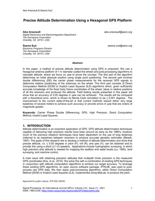
  • 11. Alex Arsenault & Seema Sud Signal Processing: An International Journal (SPIJ), Volume (14) : Issue (1) : 2021 11 ISSN: 1985-2339, https://www.cscjournals.org/journals/SPIJ/description.php fit over all antennas (Lu, et al., 1993). However, the ILS can suffer from angle ambiguities, so that different sets of pitch, roll, and yaw solve Eq. (46). 3. THEORETICAL YAW A Monte Carlo simulation was performed to determine the theoretical error in yaw. This error is based on the body frame (BF) coordinate error and GPS position error. As the amount of error in BF coordinate measurements increases, GPS position measurements must be more accurate in order to achieve the target accuracy. The error term is implemented by introducing a standard deviation in the GPS and BF coordinates in Eq. (42), used to compute yaw, and averaging over 10,000 trials to obtain the root mean-square (RMS) yaw error. Fig. 4 shows the GPS position error vs. yaw relationship for four different values of body frame coordinate error: 0 (no error), 1, 3, and 5 mm. Given that our BF coordinate error is believed to be about 1 mm at most, and the GPS coordinate errors are < 1 mm, we can use this figure to determine that the theoretically best yaw is ~ < 0.001 degrees and compare this value to our measurements in Section 5. The presence of multipath, which is a predominant source of error (Bidikar, et al., 2020), on the link will necessarily cause our yaw measurements to be worse than this theoretical value. 4. HARDWARE SETUP The GPS antennas used in this wheel were Novatel GPS-704-X, and the receivers used were U- blox M8T evaluation kit modules. The antennas are circular in shape with the phase center located roughly at the center of each receiver. When measuring the distances between antennas, an attempt was made to measure to/from the phase center of each antenna (separated by 0.5 m). The U-blox M8T receiver modules are used to generate raw GPS data, which the RTKLIB software package uses to execute the single point and carrier phase double difference relative positioning algorithms. Refer to Fig. 3 for a topological diagram of the antenna platform (the wheel) used for our method. A block diagram of the hardware setup used in field experiments to validate the ability of the algorithms to provide precise yaw measurements is shown in Fig. 5. The setup is as follows: the wheel is mounted onto a fixed platform, which supports the ensemble and does not rotate or change elevation. We use the adjustable Tribrach to level the rotating platform. We use the rotating platform to turn the wheel through its yaw axis and lock it into position for a collection event. We use a Sokkia DT540L Theodolite, mounted onto the assembly, to measure the actual yaw. The theodolite is accompanied with a viewfinder that allows us to see objects placed far away. The theodolite has an accuracy of < 5 arcseconds, or 0.0013 degrees. The experiments are performed in two steps: (1) Using the viewfinder, we point and lock the wheel and theodolite onto an LED placed on a platform about 100 meters away and record the yaw angle from the theodolite display; this is called position j = 1 and the theodolite yaw is denoted YT,1. We perform a collect and compute the yaw with our proposed algorithms; this measured yaw is denoted Ym,1; (2) We rotate the entire assembly by some arbitrary angle to position j = 2, lock the wheel assembly in place, and rotate the theodolite back to where it is pointing at the LED again, thereby allowing us to compute a second yaw angle, YT,2. The difference between YT,2 and YT,1 is the YT of the rotation. We then measure the yaw angle in position 2, Ym,2. We compute Ym = Ym,2- Ym,1 and compare this to YT from the theodolite to determine our algorithm's accuracy, where our goal is < 0.05 degrees. Note that we are measuring yaw accuracy by a yaw measurement in this experiment. In the next section, we discuss the results of field tests to demonstrate the proposed approach. Further note that the measurement accuracy is inversely proportional to the separation of the antenna elements. So, if the antenna separation is halved from 0.5 m to 0.25 m, we would expect the theoretical and measured yaw error to approximately double (Lu, et al., 1993).
  • 12. Alex Arsenault & Seema Sud Signal Processing: An International Journal (SPIJ), Volume (14) : Issue (1) : 2021 12 ISSN: 1985-2339, https://www.cscjournals.org/journals/SPIJ/description.php FIGURE 4: Theoretical GPS position error [mm] vs. yaw error [degrees]. 5. FIELD TEST RESULTS We performed three sets of tests and analyzed the collected data. For each test, the receivers collected for an hour to obtain a single yaw measurement. The first field test was performed on Jul. 20, 2020. The rotational angle that the theodolite measured was YT=7.57779 degrees, whereas the algorithms, using the ILS to compute the final yaws, measured Ym= 7:5802 degrees. This is an error of just 0.0024 degrees, well within our desired objective and close to the theoretical value of < 0.001 degrees. For this collect, the wheel was placed in a parking lot about 25 meters from a building, so our assumption is that multipath was likely minimal (Kos, et al., 2010). We performed a second set of field tests on Aug. 10, 2020 where the wheel was placed about 25 meters near a building with a car placed about 2 meters away, to assess the proposed approach when multipath is introduced (Weill, 1997). The theodolite measurement gave YT = 25.5819 degrees. Using the DCM algorithm on the RTKLIB outputs produced Ym = 25.5669 degrees. This yields an error of 0.015 degrees. It was noted during the collect that one of the antennas had convergence issues, which we later discovered was caused by a loose connection. So, we had Ym,3 = -154.5301 degrees. However, using a modulo operation to limit the value to < 90 degrees, the value used is 25.4699 degrees. If we exclude this antenna from the measurements, we obtain Ym = 25.5911 degrees, which results in an error of 0.0092 degrees, meeting the desired yaw requirement with significant margin, and coming close to theory.
  • 13. Alex Arsenault & Seema Sud Signal Processing: An International Journal (SPIJ), Volume (14) : Issue (1) : 2021 13 ISSN: 1985-2339, https://www.cscjournals.org/journals/SPIJ/description.php FIGURE 5: Hardware setup for field tests (note: distance between wheel and LED platform is ~ 100 m). A second collect on the same day, where the wheel was placed about 6 meters from the building resulted in the YT = 36.8764 degrees, Ym = 36.9009 degrees, or an error of 0.0245 degrees. Due to additional multipath from the proximity of the wheel to the building and car, the error is larger than theory and larger than in the previous tests. A longer collect could possibly improve the accuracy even further. 6. CONCLUSION This paper describes a proposed set of GPS processing algorithms to obtain extremely high accuracy in yaw measurements using a short baseline (1 m diameter) hexagonal device containing six GPS receivers. The algorithms, using RTKLIB software, apply carrier phase differencing as well as other signal processing techniques and an implicit least squares (ILS) or direct computation method (DCM) approach to obtain highly accurate yaw measurements (< 0.05) degrees. This type of accuracy has not been achieved before with a short baseline receiver system. The algorithms are discussed and a hardware test setup using a device called a theodolite is used in a set of field experiments to verify the proposed approach meets the desired accuracy. The results are also compared to a theoretical analysis and shown to come close to theory. The field tests included multipath, thereby illustrating that highly accurate yaw in the presence of multipath is possible. Applications include maritime and land surveying, and machine control, where large baselines are not practical. Future work is to reduce the form factor of the wheel and integrate the proposed algorithms into the hardware for autonomous operation. Future work also includes characterizing the multipath environment to confirm our assumptions on the severity of the multipath and to investigate and apply methods (e.g. Giorgi, 2013) to resolve ambiguous estimation errors. 7. ACKNOWLEDGMENTS The authors thank Jacob Kirschner and George Schmitt for assistance with field testing, Dr. Allan Tubbs for his guidance, Tom Jenkins for reviewing and providing helpful suggestions, and The Aerospace Corporation for funding this work. The authors also thank the anonymous reviewers for their comments that improved the quality of the paper.
  • 14. Alex Arsenault & Seema Sud Signal Processing: An International Journal (SPIJ), Volume (14) : Issue (1) : 2021 14 ISSN: 1985-2339, https://www.cscjournals.org/journals/SPIJ/description.php 8. REFERENCES Ashby, Neil (2004), The Sagnac Effect In the Global Positioning System, Dept.of Physics, Univ. of Colorado, Boulder. Bidikar, B., Chapa, B.P., Kumar, M.V., and Rao G.S. (2020), GPS Signal Multipath Error Mitigation Technique, Satellites Missions and Technologies for Geosciences. 10.5772/intechopen.92295. Bisnath, S., Aggrey, J., and Seepersad, G. (2018), Innovation: Examining Precise Point Positioning Now and in the Future, GPS World. Blewitt, G. (1997), The Basics of the GPS Technique, Department of Geomatics, The University of Newcastle. Crassidis, J.L., and Lightsey, E.G. (2001), Combined GPS and Three-Axis Magnetometer Data, Space Technology, 22(4), 147-156. Farhangian, F., Landry, R., Jr. (2020), Accuracy Improvement of Attitude Determination Systems Using EKF-Based Error Prediction Filter and PI Controller, Sensors. 10.3390/s20144055. Giorgi, G. (2013, September 25-27), Single-baseline GNSS Attitude Determination: The Problem of Degenerate Solutions, 56 th Int. Symposium ELMAR, 337-340, Zadar, Croatia. Juang, J.-C., and Huang, G.-S. (1997), Development of GPS-Based Aattitude Determination Algorithms, IEEE Trans. On Aerospace and Electronic Systems, 33(3), 968 – 976. 10.1109/7.599320. Khalil, R. (2019), Accuracy Assessment of GPS_RTK Grid to Ground Solutions, Geoinformatica: An International Journal (GIIJ), 6(3), 23-32. Kos, T., Markezic, I., and Pokrajcic, J. (2010, September 15-17), Effects of Multipath Reception on GPS Positioning Performance, 52 nd Int. Symposium ELMAR, 399-402, Zadar Croatia. Krawkiwsky, E.J. (1987), Papers for The CISM Adjustment and Analysis Seminars, The Canadian Institute of Surveying and Mapping. Lu, G. (1995), Development of a GPS Multi-Antenna System for Attitude Determination, [Doctoral Dissertation, Univ. of Calgary]. Lu, G., Cannon, M.E., and Lachapelle, G. (1993), Attitude Determination in a Survey Launch Using Multi-Antenna GPS Technologies, Dept. of Geomatics Engineering, Univ. of Calgary. Raskaliyev, A., Patel, S.H., Sobh, T.M., and Ibrayev, A. (2020), GNSS-Based Attitude Determination Techniques – A Comprehensive Literature Survey, IEEE Access, 8, 24,873- 24,886. 10.1109/ACCESS.2020.2970083. Takasu, T. (2013), RTKLIB Version 2.4.2 Manual. Teunissen, P.J.G., de Jonge, P.J., and Tiberius, C.C.J.M. (1995), The Lambda Method for Fast GPS Surveying, Faculty of Geodetic Engineering, Delft Univ. of Technology. Torge, W. (1980), Geodesy. Walter de Gruyter and Co. Weill, L.R. (1997), Conquering Multipath: The GPS Accuracy Battle, GPS World, 59-66.