SlideShare a Scribd company logo
1 of 29
Active and Reactive Power
• When a circuit has resistive and reactive parts, the
resultant power has 2 parts:
– The first is dissipated in the resistive element. This is
the active power, P
– The second is stored and returned by the reactive
element. This is the reactive power, Q , which has
units of volt amperes reactive or var
• While reactive power is not dissipated it does
have an effect on the system
– for example, it increases the current that must be
supplied and increases losses with cables
16.6
Reactive power flow in distribution system result in:
• Transformer over loads;
• Voltage drops at the end of the lines;
• Temperature rise supply cables and thus in active
power losses;
• Over sizing of harmonic protection devices.
 Reactive power (KVAR) required by inductive
loads increases the amount of apparent power
(KVA) in distribution system. This increase in
reactive and apparent power results in a larger
angle measured between KW and KVA.
As θ increases, cosine θ (or power factor)
decreases.
• Consider an
RL circuit
– the relationship
between the various
forms of power can
be illustrated using
a power triangle
• Therefore
Active PowerP = VI cos  watts
Reactive Power Q = VI sin  var
Apparent Power S = VI VA
S2 = P2 + Q2
definition : p.f. = cos  = P/ S
P.F. should be close to unity
Power Factor
• Power factor is particularly important in high-power applications
It is the measure of how effectively electrical equipment converts
electric power (supplied by your power utility) into useful power
output.
• In technical terms, it is the ratio of Active Power (kW) to the
Apparent Power (kVA) of an electrical installation.
• The PF play important role in a.c circuits since power consumed
depends on this factor.
• • 𝑷 = 𝑽𝑰 cos ∅ (for SINGLE PHASE)
• 𝑰 = 𝑷/ 𝑽 𝐜𝐨𝐬 ∅ •
• 𝑷 = √𝟑𝑽 𝑰 cos ∅ (for THREE PHASE)
• 𝑰 = 𝑷/ √𝟑𝑽 𝐜𝐨𝐬 ∅
– power companies therefore penalize industrial users who
introduce a poor power factor
Causes of low power factor :
Low power factor results when KW small in relation to KVA.
This would occur when KVAR is large.
What causes a large KVAR in a system?
• …………… Inductive loads
• All Ac motors
• Transformers
• Arc & induction heating furnance
• High intensity discharge lighting
• All devices using electromagnetic field.
Disadvantage of low power factor
• large kva rating of equipments.
• greater conductor size.
• large copper losses.
• poor voltage regulation.
• reduced handling capacity of system
Benefits for improving power factor
• Lower utility fees by
- Reducing peak KW billing demand
- Eliminating the power factor penalty
• Increased system capacity and reduced system
losses in your electrical system
• Increased voltage level in your electrical
system
• Maintain a better voltage regulation on the
system
The problem of poor power factor is tackled by
adding additional components to bring the power
factor back closer to unity
– a capacitor of an appropriate size in parallel with a
lagging load can ‘cancel out’ the inductive element
– this is power factor correction
Consumers of Reactive Power increase power
factor:
• Capacitors
• Synchronous condenser
• Phase advancer
• Reactive power (VAR) compensation is defined as the management of
reactive power to improve the performance of ac systems.
• Any device which is connected in series or parallel with load and which is
capable of supplying reactive power demanded by load is called reactive
power compensation device.
There are two aspects:-
• a) Load Compensation – The main objectives are to :-
• i) increase the power factor of the system
• ii) to balance the real power drawn from the system
• iii) compensate voltage regulation
• iv) to eliminate current harmonics.
• b) Voltage Support – The main purpose is to decrease the voltage
fluctuation at a given terminal of transmission line.
• Therefore the VAR compensation improves the stability of ac system by
increasing the maximum active power that can be transmitted.
Methods of Reactive Power Compensation
 Shunt compensation
 Series compensation
 Synchronous condensers
 Static VAR compensators
Shunt Compensation
• The device that is connected in parallel with the transmission
line is called the shunt compensator.
• For high voltage transmission line the line capacitance is high and plays a
significant role in voltage conditions of the receiving end.
• When the line is loaded then the reactive power demand of the load is
partially met by the reactive power generated by the line capacitance and
the remaining reactive power demand is met by the reactive power flow
through the line from sending end to the receiving end.
• When load is high (more than SIL) then a large reactive power flows
from sending end to the receiving end resulting in large voltage drop
in the line.
• To improve the voltage at the receiving end shunt capacitors may be
connected at the receiving end to generate and feed the reactive
power to the load so that reactive power flow through the line and
consequently the voltage drop in the line is reduced.
• To control the receiving end voltage a bank of capacitors (large
number of capacitors connected in parallel) is installed at the
receiving end and suitable number of capacitors are switched
in during high load condition depending upon the load
demand.
• Thus the capacitors provide leading VAr to partially meet
reactive power demand of the load to control the voltage.
• If XC = 1/ωC be the reactance of the shunt capacitor then the
reactive power generated of leading VAr supplied by the
capacitor:
• where, |V2| is the magnitude of receiving end voltage.
C
V
X
V
Q
C
C 
2
2
2
2


• When load is small (less than SIL) then the load reactive
power demand may even be lesser than the reactive power
generated by the line capacitor. Under these conditions the
reactive power flow through the line becomes negative, i.e.,
the reactive power flows from receiving end to sending end,
and the receiving end voltage is higher than sending end
voltage (Ferranti effect).
• To control the voltage at the receiving end it is necessary to
absorb or sink reactive power. This is achieved by
connecting shunt reactors at the receiving end.
• If XL = ωL be the reactance of the shunt reactor (inductor)
then the reactive VAr absorbed by the shunt rector:
• where, |V2| is the magnitude of receiving end voltage.
L
V
X
V
Q
L
L 
/
2
2
2
2


• To control the receiving end voltage generally one shunt rector is
installed and switched in during the light load condition.
• To meet the variable reactive power demands requisite number of shunt
capacitors are switched in, in addition to the shunt reactor, which results
in adjustable reactive power absorption by the combination.
• For high voltage transmission line the line capacitance is high and plays
a significant role in voltage conditions of the receiving end.
• When the line is loaded then the reactive power demand of the load is
partially met by the reactive power generated by the line capacitance and
the remaining reactive power demand is met by the reactive power flow
through the line from sending end to the receiving end.
a) uncompensated transmission line b) compensated transmission line
Advantages of Series Compensation
1. Increase in transmission capacity
– The power transfer capacity of a line is given by

sin
.
X
V
E
P 
where, E , V are sending and receiving end voltages
X is reactance of line & δ is phase angle between E and V
• Power transfer without and with compensation:
K
X
X
X
X
X
P
P
X
X
V
E
P
X
V
E
P
L
C
C
L
L
C
L
L









1
1
)
/
1
(
1
)
(
sin
)
(
.
sin
.
1
2
2
1


2. Improvement of System Stability
• For same amount of power transfer and same value of E
and V, the δ in the case of series compensated line is less
than that of uncompensated line.
L
C
L
C
L
L
X
X
X
X
X
V
E
P
X
V
E
P
)
(
sin
sin
sin
)
(
.
sin
.
1
2
2
1









• A lower δ means better system stability
• Series compensation offers most economic solution for
system stability as compared to other methods (reducing
generator, x-mer reactance, bundled conductors, increase
no. of parallel circuits
Disadvantages
1. Increase in fault current
2. Mal operation of distance relay- if the degree
of compensation and location is not proper.
3. High recovery voltage of lines- across the
circuit breaker contacts and is harmful.
Active Compensation
• Synchronous condensers are the active shunt
compensators and have been used to improve the
voltage profile and system stability.
• When machine is overexcited, it acts as shunt
capacitor as it supplies lagging VAr to the system
and when under excited it acts as a shunt coil as it
absorbs reactive power to maintain terminal
voltage.
• The synchronous condenser provides continuous
(step less) adjustment of the reactive power in
both under excited and overexcited mode.
Objective Series Capacitors Shunt Capacitors
Improving Power
Factor
Secondary Primary
Improving Voltage
level in overhead line
system with a normal
and low Power
Factor
Primary Secondary
Improving Voltage
level in overhead line
system with a high
Power Factor
Not Used Primary
Reduce Line Losses Secondary Primary
Reduce Voltage
Fluctuations
Primary Not used

More Related Content

What's hot

Sequence impedances of transformers 
Sequence impedances of transformers Sequence impedances of transformers 
Sequence impedances of transformers Muhammad Moin
 
TRANSMISSION LINES and capacity.pptx
TRANSMISSION LINES and capacity.pptxTRANSMISSION LINES and capacity.pptx
TRANSMISSION LINES and capacity.pptxSatish Pydimarla
 
Power systems symmetrical components
Power systems symmetrical componentsPower systems symmetrical components
Power systems symmetrical componentsanoopeluvathingal
 
Methods of voltage control
Methods of voltage controlMethods of voltage control
Methods of voltage controlv Kalairajan
 
Static shunt compensation
Static shunt compensationStatic shunt compensation
Static shunt compensationAyyarao T S L V
 
Reactive power and voltage control
Reactive power and voltage controlReactive power and voltage control
Reactive power and voltage controlSourabh sharma
 
Disadvantages of corona, radio interference, inductive interference between p...
Disadvantages of corona, radio interference, inductive interference between p...Disadvantages of corona, radio interference, inductive interference between p...
Disadvantages of corona, radio interference, inductive interference between p...vishalgohel12195
 
static series synchronus compensator
static series synchronus compensatorstatic series synchronus compensator
static series synchronus compensatorbhupendra kumar
 
Chapter 4 mechanical design of transmission lines
Chapter 4  mechanical design of transmission linesChapter 4  mechanical design of transmission lines
Chapter 4 mechanical design of transmission linesfiraoltemesgen1
 
Measurement of high_voltage_and_high_currentunit_iv_full_version
Measurement of high_voltage_and_high_currentunit_iv_full_versionMeasurement of high_voltage_and_high_currentunit_iv_full_version
Measurement of high_voltage_and_high_currentunit_iv_full_versionAman Ansari
 
Simplified analysis of graetz circuit copy - copy
Simplified analysis of graetz circuit   copy - copySimplified analysis of graetz circuit   copy - copy
Simplified analysis of graetz circuit copy - copyVert Wheeler
 
Facts static voltage & phase angle regulators
Facts   static voltage & phase angle regulatorsFacts   static voltage & phase angle regulators
Facts static voltage & phase angle regulatorsSITCOE, Yadrav
 
Principles of Power Systems V.K Mehta Complete Book - Chapter 6
Principles of Power Systems V.K Mehta Complete Book - Chapter 6Principles of Power Systems V.K Mehta Complete Book - Chapter 6
Principles of Power Systems V.K Mehta Complete Book - Chapter 6Power System Operation
 
File 1 power system fault analysis
File 1 power system fault analysisFile 1 power system fault analysis
File 1 power system fault analysiskirkusawi
 

What's hot (20)

Sequence impedances of transformers 
Sequence impedances of transformers Sequence impedances of transformers 
Sequence impedances of transformers 
 
Power flow analysis
Power flow analysisPower flow analysis
Power flow analysis
 
TRANSMISSION LINES and capacity.pptx
TRANSMISSION LINES and capacity.pptxTRANSMISSION LINES and capacity.pptx
TRANSMISSION LINES and capacity.pptx
 
load flow 1
 load flow 1 load flow 1
load flow 1
 
Power systems symmetrical components
Power systems symmetrical componentsPower systems symmetrical components
Power systems symmetrical components
 
Power systems İntroduction
Power systems İntroductionPower systems İntroduction
Power systems İntroduction
 
Ps ppt by saran
Ps  ppt by saranPs  ppt by saran
Ps ppt by saran
 
Methods of voltage control
Methods of voltage controlMethods of voltage control
Methods of voltage control
 
Static shunt compensation
Static shunt compensationStatic shunt compensation
Static shunt compensation
 
Reactive power and voltage control
Reactive power and voltage controlReactive power and voltage control
Reactive power and voltage control
 
Disadvantages of corona, radio interference, inductive interference between p...
Disadvantages of corona, radio interference, inductive interference between p...Disadvantages of corona, radio interference, inductive interference between p...
Disadvantages of corona, radio interference, inductive interference between p...
 
static series synchronus compensator
static series synchronus compensatorstatic series synchronus compensator
static series synchronus compensator
 
Chapter 4 mechanical design of transmission lines
Chapter 4  mechanical design of transmission linesChapter 4  mechanical design of transmission lines
Chapter 4 mechanical design of transmission lines
 
UPS Sizing
UPS SizingUPS Sizing
UPS Sizing
 
Measurement of high_voltage_and_high_currentunit_iv_full_version
Measurement of high_voltage_and_high_currentunit_iv_full_versionMeasurement of high_voltage_and_high_currentunit_iv_full_version
Measurement of high_voltage_and_high_currentunit_iv_full_version
 
Simplified analysis of graetz circuit copy - copy
Simplified analysis of graetz circuit   copy - copySimplified analysis of graetz circuit   copy - copy
Simplified analysis of graetz circuit copy - copy
 
Facts static voltage & phase angle regulators
Facts   static voltage & phase angle regulatorsFacts   static voltage & phase angle regulators
Facts static voltage & phase angle regulators
 
Neutral grounding
Neutral groundingNeutral grounding
Neutral grounding
 
Principles of Power Systems V.K Mehta Complete Book - Chapter 6
Principles of Power Systems V.K Mehta Complete Book - Chapter 6Principles of Power Systems V.K Mehta Complete Book - Chapter 6
Principles of Power Systems V.K Mehta Complete Book - Chapter 6
 
File 1 power system fault analysis
File 1 power system fault analysisFile 1 power system fault analysis
File 1 power system fault analysis
 

Similar to power-factor-correction.pptx

Unit 2 Reactive Power Management
Unit 2 Reactive Power ManagementUnit 2 Reactive Power Management
Unit 2 Reactive Power ManagementSANTOSH GADEKAR
 
Application of Capacitors to Distribution System and Voltage Regulation
Application of Capacitors to Distribution System and Voltage RegulationApplication of Capacitors to Distribution System and Voltage Regulation
Application of Capacitors to Distribution System and Voltage RegulationAmeen San
 
Series & shunt compensation and FACTs Devices
Series & shunt compensation and FACTs DevicesSeries & shunt compensation and FACTs Devices
Series & shunt compensation and FACTs Deviceskhemraj298
 
Reactivepowercompensation 140401183847-phpapp01 (6)
Reactivepowercompensation 140401183847-phpapp01 (6)Reactivepowercompensation 140401183847-phpapp01 (6)
Reactivepowercompensation 140401183847-phpapp01 (6)REVANTH CHINTU
 
Reactive power compensation
Reactive power compensationReactive power compensation
Reactive power compensationVikas Saini
 
Reactive power compensation
Reactive power compensationReactive power compensation
Reactive power compensationVikas Saini
 
17-conventional transmission control capabilities; Interline Power Flow Contr...
17-conventional transmission control capabilities; Interline Power Flow Contr...17-conventional transmission control capabilities; Interline Power Flow Contr...
17-conventional transmission control capabilities; Interline Power Flow Contr...RahulJain989779
 
Reactive power consumption in modern power system
Reactive power consumption in modern power systemReactive power consumption in modern power system
Reactive power consumption in modern power systemRahuldey1991
 
REACTIVE POWER
REACTIVE POWERREACTIVE POWER
REACTIVE POWERJeetDatta3
 
Reactive Power : Problems and Solutions
Reactive Power : Problems and SolutionsReactive Power : Problems and Solutions
Reactive Power : Problems and SolutionsAbhinav Dubey
 
Power system voltage stability
Power system voltage stabilityPower system voltage stability
Power system voltage stabilityAkash Choudhary
 
Power system voltage stability
Power system voltage stabilityPower system voltage stability
Power system voltage stabilityAkash Choudhary
 
Power Factor
Power FactorPower Factor
Power FactorTim Cohen
 
COMPENSATION OF REACTIVE POWER
COMPENSATION OF REACTIVE POWERCOMPENSATION OF REACTIVE POWER
COMPENSATION OF REACTIVE POWERST Chowhury
 
1590053 634881478003587500
1590053 6348814780035875001590053 634881478003587500
1590053 634881478003587500Navyasri Jiguru
 

Similar to power-factor-correction.pptx (20)

Unit 2 Reactive Power Management
Unit 2 Reactive Power ManagementUnit 2 Reactive Power Management
Unit 2 Reactive Power Management
 
Application of Capacitors to Distribution System and Voltage Regulation
Application of Capacitors to Distribution System and Voltage RegulationApplication of Capacitors to Distribution System and Voltage Regulation
Application of Capacitors to Distribution System and Voltage Regulation
 
Series & shunt compensation and FACTs Devices
Series & shunt compensation and FACTs DevicesSeries & shunt compensation and FACTs Devices
Series & shunt compensation and FACTs Devices
 
Reactivepowercompensation 140401183847-phpapp01 (6)
Reactivepowercompensation 140401183847-phpapp01 (6)Reactivepowercompensation 140401183847-phpapp01 (6)
Reactivepowercompensation 140401183847-phpapp01 (6)
 
Reactive power compensation
Reactive power compensationReactive power compensation
Reactive power compensation
 
Reactive power compensation
Reactive power compensationReactive power compensation
Reactive power compensation
 
IARE_RPCM_PPT_0.pdf
IARE_RPCM_PPT_0.pdfIARE_RPCM_PPT_0.pdf
IARE_RPCM_PPT_0.pdf
 
17-conventional transmission control capabilities; Interline Power Flow Contr...
17-conventional transmission control capabilities; Interline Power Flow Contr...17-conventional transmission control capabilities; Interline Power Flow Contr...
17-conventional transmission control capabilities; Interline Power Flow Contr...
 
Reactive power consumption in modern power system
Reactive power consumption in modern power systemReactive power consumption in modern power system
Reactive power consumption in modern power system
 
REACTIVE POWER
REACTIVE POWERREACTIVE POWER
REACTIVE POWER
 
Reactive Power : Problems and Solutions
Reactive Power : Problems and SolutionsReactive Power : Problems and Solutions
Reactive Power : Problems and Solutions
 
THE POWER FACTOR
THE POWER FACTOR THE POWER FACTOR
THE POWER FACTOR
 
Power factor
Power factorPower factor
Power factor
 
Power system voltage stability
Power system voltage stabilityPower system voltage stability
Power system voltage stability
 
Power system voltage stability
Power system voltage stabilityPower system voltage stability
Power system voltage stability
 
Power factor improvement
Power factor improvementPower factor improvement
Power factor improvement
 
Power Factor
Power FactorPower Factor
Power Factor
 
EDS Unit 5.pptx
EDS Unit 5.pptxEDS Unit 5.pptx
EDS Unit 5.pptx
 
COMPENSATION OF REACTIVE POWER
COMPENSATION OF REACTIVE POWERCOMPENSATION OF REACTIVE POWER
COMPENSATION OF REACTIVE POWER
 
1590053 634881478003587500
1590053 6348814780035875001590053 634881478003587500
1590053 634881478003587500
 

Recently uploaded

Software Development Life Cycle By Team Orange (Dept. of Pharmacy)
Software Development Life Cycle By  Team Orange (Dept. of Pharmacy)Software Development Life Cycle By  Team Orange (Dept. of Pharmacy)
Software Development Life Cycle By Team Orange (Dept. of Pharmacy)Suman Mia
 
IMPLICATIONS OF THE ABOVE HOLISTIC UNDERSTANDING OF HARMONY ON PROFESSIONAL E...
IMPLICATIONS OF THE ABOVE HOLISTIC UNDERSTANDING OF HARMONY ON PROFESSIONAL E...IMPLICATIONS OF THE ABOVE HOLISTIC UNDERSTANDING OF HARMONY ON PROFESSIONAL E...
IMPLICATIONS OF THE ABOVE HOLISTIC UNDERSTANDING OF HARMONY ON PROFESSIONAL E...RajaP95
 
(MEERA) Dapodi Call Girls Just Call 7001035870 [ Cash on Delivery ] Pune Escorts
(MEERA) Dapodi Call Girls Just Call 7001035870 [ Cash on Delivery ] Pune Escorts(MEERA) Dapodi Call Girls Just Call 7001035870 [ Cash on Delivery ] Pune Escorts
(MEERA) Dapodi Call Girls Just Call 7001035870 [ Cash on Delivery ] Pune Escortsranjana rawat
 
Model Call Girl in Narela Delhi reach out to us at 🔝8264348440🔝
Model Call Girl in Narela Delhi reach out to us at 🔝8264348440🔝Model Call Girl in Narela Delhi reach out to us at 🔝8264348440🔝
Model Call Girl in Narela Delhi reach out to us at 🔝8264348440🔝soniya singh
 
Decoding Kotlin - Your guide to solving the mysterious in Kotlin.pptx
Decoding Kotlin - Your guide to solving the mysterious in Kotlin.pptxDecoding Kotlin - Your guide to solving the mysterious in Kotlin.pptx
Decoding Kotlin - Your guide to solving the mysterious in Kotlin.pptxJoão Esperancinha
 
High Profile Call Girls Nashik Megha 7001305949 Independent Escort Service Na...
High Profile Call Girls Nashik Megha 7001305949 Independent Escort Service Na...High Profile Call Girls Nashik Megha 7001305949 Independent Escort Service Na...
High Profile Call Girls Nashik Megha 7001305949 Independent Escort Service Na...Call Girls in Nagpur High Profile
 
IVE Industry Focused Event - Defence Sector 2024
IVE Industry Focused Event - Defence Sector 2024IVE Industry Focused Event - Defence Sector 2024
IVE Industry Focused Event - Defence Sector 2024Mark Billinghurst
 
Call Girls in Nagpur Suman Call 7001035870 Meet With Nagpur Escorts
Call Girls in Nagpur Suman Call 7001035870 Meet With Nagpur EscortsCall Girls in Nagpur Suman Call 7001035870 Meet With Nagpur Escorts
Call Girls in Nagpur Suman Call 7001035870 Meet With Nagpur EscortsCall Girls in Nagpur High Profile
 
Call Girls Delhi {Jodhpur} 9711199012 high profile service
Call Girls Delhi {Jodhpur} 9711199012 high profile serviceCall Girls Delhi {Jodhpur} 9711199012 high profile service
Call Girls Delhi {Jodhpur} 9711199012 high profile servicerehmti665
 
Biology for Computer Engineers Course Handout.pptx
Biology for Computer Engineers Course Handout.pptxBiology for Computer Engineers Course Handout.pptx
Biology for Computer Engineers Course Handout.pptxDeepakSakkari2
 
MANUFACTURING PROCESS-II UNIT-2 LATHE MACHINE
MANUFACTURING PROCESS-II UNIT-2 LATHE MACHINEMANUFACTURING PROCESS-II UNIT-2 LATHE MACHINE
MANUFACTURING PROCESS-II UNIT-2 LATHE MACHINESIVASHANKAR N
 
SPICE PARK APR2024 ( 6,793 SPICE Models )
SPICE PARK APR2024 ( 6,793 SPICE Models )SPICE PARK APR2024 ( 6,793 SPICE Models )
SPICE PARK APR2024 ( 6,793 SPICE Models )Tsuyoshi Horigome
 
HARMONY IN THE NATURE AND EXISTENCE - Unit-IV
HARMONY IN THE NATURE AND EXISTENCE - Unit-IVHARMONY IN THE NATURE AND EXISTENCE - Unit-IV
HARMONY IN THE NATURE AND EXISTENCE - Unit-IVRajaP95
 
Sheet Pile Wall Design and Construction: A Practical Guide for Civil Engineer...
Sheet Pile Wall Design and Construction: A Practical Guide for Civil Engineer...Sheet Pile Wall Design and Construction: A Practical Guide for Civil Engineer...
Sheet Pile Wall Design and Construction: A Practical Guide for Civil Engineer...Dr.Costas Sachpazis
 
What are the advantages and disadvantages of membrane structures.pptx
What are the advantages and disadvantages of membrane structures.pptxWhat are the advantages and disadvantages of membrane structures.pptx
What are the advantages and disadvantages of membrane structures.pptxwendy cai
 
Introduction and different types of Ethernet.pptx
Introduction and different types of Ethernet.pptxIntroduction and different types of Ethernet.pptx
Introduction and different types of Ethernet.pptxupamatechverse
 
Introduction to Multiple Access Protocol.pptx
Introduction to Multiple Access Protocol.pptxIntroduction to Multiple Access Protocol.pptx
Introduction to Multiple Access Protocol.pptxupamatechverse
 
College Call Girls Nashik Nehal 7001305949 Independent Escort Service Nashik
College Call Girls Nashik Nehal 7001305949 Independent Escort Service NashikCollege Call Girls Nashik Nehal 7001305949 Independent Escort Service Nashik
College Call Girls Nashik Nehal 7001305949 Independent Escort Service NashikCall Girls in Nagpur High Profile
 

Recently uploaded (20)

Software Development Life Cycle By Team Orange (Dept. of Pharmacy)
Software Development Life Cycle By  Team Orange (Dept. of Pharmacy)Software Development Life Cycle By  Team Orange (Dept. of Pharmacy)
Software Development Life Cycle By Team Orange (Dept. of Pharmacy)
 
9953056974 Call Girls In South Ex, Escorts (Delhi) NCR.pdf
9953056974 Call Girls In South Ex, Escorts (Delhi) NCR.pdf9953056974 Call Girls In South Ex, Escorts (Delhi) NCR.pdf
9953056974 Call Girls In South Ex, Escorts (Delhi) NCR.pdf
 
IMPLICATIONS OF THE ABOVE HOLISTIC UNDERSTANDING OF HARMONY ON PROFESSIONAL E...
IMPLICATIONS OF THE ABOVE HOLISTIC UNDERSTANDING OF HARMONY ON PROFESSIONAL E...IMPLICATIONS OF THE ABOVE HOLISTIC UNDERSTANDING OF HARMONY ON PROFESSIONAL E...
IMPLICATIONS OF THE ABOVE HOLISTIC UNDERSTANDING OF HARMONY ON PROFESSIONAL E...
 
(MEERA) Dapodi Call Girls Just Call 7001035870 [ Cash on Delivery ] Pune Escorts
(MEERA) Dapodi Call Girls Just Call 7001035870 [ Cash on Delivery ] Pune Escorts(MEERA) Dapodi Call Girls Just Call 7001035870 [ Cash on Delivery ] Pune Escorts
(MEERA) Dapodi Call Girls Just Call 7001035870 [ Cash on Delivery ] Pune Escorts
 
Model Call Girl in Narela Delhi reach out to us at 🔝8264348440🔝
Model Call Girl in Narela Delhi reach out to us at 🔝8264348440🔝Model Call Girl in Narela Delhi reach out to us at 🔝8264348440🔝
Model Call Girl in Narela Delhi reach out to us at 🔝8264348440🔝
 
Decoding Kotlin - Your guide to solving the mysterious in Kotlin.pptx
Decoding Kotlin - Your guide to solving the mysterious in Kotlin.pptxDecoding Kotlin - Your guide to solving the mysterious in Kotlin.pptx
Decoding Kotlin - Your guide to solving the mysterious in Kotlin.pptx
 
High Profile Call Girls Nashik Megha 7001305949 Independent Escort Service Na...
High Profile Call Girls Nashik Megha 7001305949 Independent Escort Service Na...High Profile Call Girls Nashik Megha 7001305949 Independent Escort Service Na...
High Profile Call Girls Nashik Megha 7001305949 Independent Escort Service Na...
 
IVE Industry Focused Event - Defence Sector 2024
IVE Industry Focused Event - Defence Sector 2024IVE Industry Focused Event - Defence Sector 2024
IVE Industry Focused Event - Defence Sector 2024
 
Call Girls in Nagpur Suman Call 7001035870 Meet With Nagpur Escorts
Call Girls in Nagpur Suman Call 7001035870 Meet With Nagpur EscortsCall Girls in Nagpur Suman Call 7001035870 Meet With Nagpur Escorts
Call Girls in Nagpur Suman Call 7001035870 Meet With Nagpur Escorts
 
Call Girls Delhi {Jodhpur} 9711199012 high profile service
Call Girls Delhi {Jodhpur} 9711199012 high profile serviceCall Girls Delhi {Jodhpur} 9711199012 high profile service
Call Girls Delhi {Jodhpur} 9711199012 high profile service
 
Biology for Computer Engineers Course Handout.pptx
Biology for Computer Engineers Course Handout.pptxBiology for Computer Engineers Course Handout.pptx
Biology for Computer Engineers Course Handout.pptx
 
MANUFACTURING PROCESS-II UNIT-2 LATHE MACHINE
MANUFACTURING PROCESS-II UNIT-2 LATHE MACHINEMANUFACTURING PROCESS-II UNIT-2 LATHE MACHINE
MANUFACTURING PROCESS-II UNIT-2 LATHE MACHINE
 
SPICE PARK APR2024 ( 6,793 SPICE Models )
SPICE PARK APR2024 ( 6,793 SPICE Models )SPICE PARK APR2024 ( 6,793 SPICE Models )
SPICE PARK APR2024 ( 6,793 SPICE Models )
 
HARMONY IN THE NATURE AND EXISTENCE - Unit-IV
HARMONY IN THE NATURE AND EXISTENCE - Unit-IVHARMONY IN THE NATURE AND EXISTENCE - Unit-IV
HARMONY IN THE NATURE AND EXISTENCE - Unit-IV
 
Sheet Pile Wall Design and Construction: A Practical Guide for Civil Engineer...
Sheet Pile Wall Design and Construction: A Practical Guide for Civil Engineer...Sheet Pile Wall Design and Construction: A Practical Guide for Civil Engineer...
Sheet Pile Wall Design and Construction: A Practical Guide for Civil Engineer...
 
What are the advantages and disadvantages of membrane structures.pptx
What are the advantages and disadvantages of membrane structures.pptxWhat are the advantages and disadvantages of membrane structures.pptx
What are the advantages and disadvantages of membrane structures.pptx
 
Introduction and different types of Ethernet.pptx
Introduction and different types of Ethernet.pptxIntroduction and different types of Ethernet.pptx
Introduction and different types of Ethernet.pptx
 
Introduction to Multiple Access Protocol.pptx
Introduction to Multiple Access Protocol.pptxIntroduction to Multiple Access Protocol.pptx
Introduction to Multiple Access Protocol.pptx
 
Call Us -/9953056974- Call Girls In Vikaspuri-/- Delhi NCR
Call Us -/9953056974- Call Girls In Vikaspuri-/- Delhi NCRCall Us -/9953056974- Call Girls In Vikaspuri-/- Delhi NCR
Call Us -/9953056974- Call Girls In Vikaspuri-/- Delhi NCR
 
College Call Girls Nashik Nehal 7001305949 Independent Escort Service Nashik
College Call Girls Nashik Nehal 7001305949 Independent Escort Service NashikCollege Call Girls Nashik Nehal 7001305949 Independent Escort Service Nashik
College Call Girls Nashik Nehal 7001305949 Independent Escort Service Nashik
 

power-factor-correction.pptx

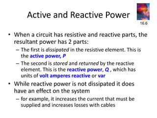
  • 1. Active and Reactive Power • When a circuit has resistive and reactive parts, the resultant power has 2 parts: – The first is dissipated in the resistive element. This is the active power, P – The second is stored and returned by the reactive element. This is the reactive power, Q , which has units of volt amperes reactive or var • While reactive power is not dissipated it does have an effect on the system – for example, it increases the current that must be supplied and increases losses with cables 16.6
  • 2. Reactive power flow in distribution system result in: • Transformer over loads; • Voltage drops at the end of the lines; • Temperature rise supply cables and thus in active power losses; • Over sizing of harmonic protection devices.  Reactive power (KVAR) required by inductive loads increases the amount of apparent power (KVA) in distribution system. This increase in reactive and apparent power results in a larger angle measured between KW and KVA. As θ increases, cosine θ (or power factor) decreases.
  • 3. • Consider an RL circuit – the relationship between the various forms of power can be illustrated using a power triangle
  • 4. • Therefore Active PowerP = VI cos  watts Reactive Power Q = VI sin  var Apparent Power S = VI VA S2 = P2 + Q2 definition : p.f. = cos  = P/ S P.F. should be close to unity
  • 5. Power Factor • Power factor is particularly important in high-power applications It is the measure of how effectively electrical equipment converts electric power (supplied by your power utility) into useful power output. • In technical terms, it is the ratio of Active Power (kW) to the Apparent Power (kVA) of an electrical installation. • The PF play important role in a.c circuits since power consumed depends on this factor. • • 𝑷 = 𝑽𝑰 cos ∅ (for SINGLE PHASE) • 𝑰 = 𝑷/ 𝑽 𝐜𝐨𝐬 ∅ • • 𝑷 = √𝟑𝑽 𝑰 cos ∅ (for THREE PHASE) • 𝑰 = 𝑷/ √𝟑𝑽 𝐜𝐨𝐬 ∅ – power companies therefore penalize industrial users who introduce a poor power factor
  • 6. Causes of low power factor : Low power factor results when KW small in relation to KVA. This would occur when KVAR is large. What causes a large KVAR in a system? • …………… Inductive loads • All Ac motors • Transformers • Arc & induction heating furnance • High intensity discharge lighting • All devices using electromagnetic field. Disadvantage of low power factor • large kva rating of equipments. • greater conductor size. • large copper losses. • poor voltage regulation. • reduced handling capacity of system
  • 7. Benefits for improving power factor • Lower utility fees by - Reducing peak KW billing demand - Eliminating the power factor penalty • Increased system capacity and reduced system losses in your electrical system • Increased voltage level in your electrical system • Maintain a better voltage regulation on the system
  • 8. The problem of poor power factor is tackled by adding additional components to bring the power factor back closer to unity – a capacitor of an appropriate size in parallel with a lagging load can ‘cancel out’ the inductive element – this is power factor correction Consumers of Reactive Power increase power factor: • Capacitors • Synchronous condenser • Phase advancer
  • 9.
  • 10.
  • 11.
  • 12.
  • 13.
  • 14.
  • 15. • Reactive power (VAR) compensation is defined as the management of reactive power to improve the performance of ac systems. • Any device which is connected in series or parallel with load and which is capable of supplying reactive power demanded by load is called reactive power compensation device. There are two aspects:- • a) Load Compensation – The main objectives are to :- • i) increase the power factor of the system • ii) to balance the real power drawn from the system • iii) compensate voltage regulation • iv) to eliminate current harmonics. • b) Voltage Support – The main purpose is to decrease the voltage fluctuation at a given terminal of transmission line. • Therefore the VAR compensation improves the stability of ac system by increasing the maximum active power that can be transmitted. Methods of Reactive Power Compensation  Shunt compensation  Series compensation  Synchronous condensers  Static VAR compensators
  • 16. Shunt Compensation • The device that is connected in parallel with the transmission line is called the shunt compensator. • For high voltage transmission line the line capacitance is high and plays a significant role in voltage conditions of the receiving end. • When the line is loaded then the reactive power demand of the load is partially met by the reactive power generated by the line capacitance and the remaining reactive power demand is met by the reactive power flow through the line from sending end to the receiving end. • When load is high (more than SIL) then a large reactive power flows from sending end to the receiving end resulting in large voltage drop in the line. • To improve the voltage at the receiving end shunt capacitors may be connected at the receiving end to generate and feed the reactive power to the load so that reactive power flow through the line and consequently the voltage drop in the line is reduced.
  • 17. • To control the receiving end voltage a bank of capacitors (large number of capacitors connected in parallel) is installed at the receiving end and suitable number of capacitors are switched in during high load condition depending upon the load demand. • Thus the capacitors provide leading VAr to partially meet reactive power demand of the load to control the voltage. • If XC = 1/ωC be the reactance of the shunt capacitor then the reactive power generated of leading VAr supplied by the capacitor: • where, |V2| is the magnitude of receiving end voltage. C V X V Q C C  2 2 2 2  
  • 18. • When load is small (less than SIL) then the load reactive power demand may even be lesser than the reactive power generated by the line capacitor. Under these conditions the reactive power flow through the line becomes negative, i.e., the reactive power flows from receiving end to sending end, and the receiving end voltage is higher than sending end voltage (Ferranti effect). • To control the voltage at the receiving end it is necessary to absorb or sink reactive power. This is achieved by connecting shunt reactors at the receiving end. • If XL = ωL be the reactance of the shunt reactor (inductor) then the reactive VAr absorbed by the shunt rector: • where, |V2| is the magnitude of receiving end voltage. L V X V Q L L  / 2 2 2 2  
  • 19. • To control the receiving end voltage generally one shunt rector is installed and switched in during the light load condition. • To meet the variable reactive power demands requisite number of shunt capacitors are switched in, in addition to the shunt reactor, which results in adjustable reactive power absorption by the combination. • For high voltage transmission line the line capacitance is high and plays a significant role in voltage conditions of the receiving end. • When the line is loaded then the reactive power demand of the load is partially met by the reactive power generated by the line capacitance and the remaining reactive power demand is met by the reactive power flow through the line from sending end to the receiving end. a) uncompensated transmission line b) compensated transmission line
  • 20.
  • 21. Advantages of Series Compensation 1. Increase in transmission capacity – The power transfer capacity of a line is given by  sin . X V E P  where, E , V are sending and receiving end voltages X is reactance of line & δ is phase angle between E and V • Power transfer without and with compensation: K X X X X X P P X X V E P X V E P L C C L L C L L          1 1 ) / 1 ( 1 ) ( sin ) ( . sin . 1 2 2 1  
  • 22. 2. Improvement of System Stability • For same amount of power transfer and same value of E and V, the δ in the case of series compensated line is less than that of uncompensated line. L C L C L L X X X X X V E P X V E P ) ( sin sin sin ) ( . sin . 1 2 2 1          • A lower δ means better system stability • Series compensation offers most economic solution for system stability as compared to other methods (reducing generator, x-mer reactance, bundled conductors, increase no. of parallel circuits
  • 23. Disadvantages 1. Increase in fault current 2. Mal operation of distance relay- if the degree of compensation and location is not proper. 3. High recovery voltage of lines- across the circuit breaker contacts and is harmful.
  • 24. Active Compensation • Synchronous condensers are the active shunt compensators and have been used to improve the voltage profile and system stability. • When machine is overexcited, it acts as shunt capacitor as it supplies lagging VAr to the system and when under excited it acts as a shunt coil as it absorbs reactive power to maintain terminal voltage. • The synchronous condenser provides continuous (step less) adjustment of the reactive power in both under excited and overexcited mode.
  • 25.
  • 26.
  • 27.
  • 28.
  • 29. Objective Series Capacitors Shunt Capacitors Improving Power Factor Secondary Primary Improving Voltage level in overhead line system with a normal and low Power Factor Primary Secondary Improving Voltage level in overhead line system with a high Power Factor Not Used Primary Reduce Line Losses Secondary Primary Reduce Voltage Fluctuations Primary Not used