SlideShare a Scribd company logo
1 of 31
Download to read offline
Subscriber access provided by Virgina Commonwealth University Libraries & VIVA (Virtual Library of Virginia)
ACS Applied Materials & Interfaces is published by the American Chemical Society.
1155 Sixteenth Street N.W., Washington, DC 20036
Published by American Chemical Society. Copyright © American Chemical Society.
However, no copyright claim is made to original U.S. Government works, or works
produced by employees of any Commonwealth realm Crown government in the course
of their duties.
Article
Highly Transparent and Durable Superhydrophobic Hybrid
Nanoporous Coatings Fabricated from Polysiloxane
Ding Wang, Zongbo Zhang, Yongming Li, and Caihong Xu
ACS Appl. Mater. Interfaces, Just Accepted Manuscript • DOI: 10.1021/am405884x • Publication Date (Web): 10 Feb 2014
Downloaded from http://pubs.acs.org on April 5, 2014
Just Accepted
“Just Accepted” manuscripts have been peer-reviewed and accepted for publication. They are posted
online prior to technical editing, formatting for publication and author proofing. The American Chemical
Society provides “Just Accepted” as a free service to the research community to expedite the
dissemination of scientific material as soon as possible after acceptance. “Just Accepted” manuscripts
appear in full in PDF format accompanied by an HTML abstract. “Just Accepted” manuscripts have been
fully peer reviewed, but should not be considered the official version of record. They are accessible to all
readers and citable by the Digital Object Identifier (DOI®). “Just Accepted” is an optional service offered
to authors. Therefore, the “Just Accepted” Web site may not include all articles that will be published
in the journal. After a manuscript is technically edited and formatted, it will be removed from the “Just
Accepted” Web site and published as an ASAP article. Note that technical editing may introduce minor
changes to the manuscript text and/or graphics which could affect content, and all legal disclaimers
and ethical guidelines that apply to the journal pertain. ACS cannot be held responsible for errors
or consequences arising from the use of information contained in these “Just Accepted” manuscripts.
1
Highly Transparent and Durable Superhydrophobic
Hybrid Nanoporous Coatings Fabricated from
Polysiloxane
Ding Wang,†,‡
Zongbo Zhang,†
Yongming Li,*,†
and Caihong Xu*,†
†
Beijing National Laboratory for Molecular Sciences, Institute of Chemistry, Chinese Academy
of Sciences, Beijing 100190, P.R. China.
‡
University of Chinese Academy of Sciences, Beijing 100049, P.R. China.
KEYWORDS. superhydrophobicity, transparency, organic-inorganic hybrid, solidification-
induced phase separation, Wenzel–Cassie transition
ABSTRACT. Highly transparent and durable superhydrophobic hybrid nanoporous coatings with
different surface roughnesses were fabricated via a simple solidification-induced phase-
separation method using a liquid polysiloxane (PSO) containing Si–H and Si–CH=CH2 groups as
the precursor and methyl-terminated polydimethylsiloxanes (PDMS) as porogens. Owing to the
existence of Si–CHn units, the hybrid material is intrinsically hydrophobic without modification
with expensive fluorinated reagents. The roughness of the coating can be easily controlled at the
nanometer scale by changing the viscosity of the PDMS to achieve both superhydrophobicity
and high transparency. The influence of surface roughness on the transparency and
Page 1 of 30
ACS Paragon Plus Environment
ACS Applied Materials & Interfaces
1
2
3
4
5
6
7
8
9
10
11
12
13
14
15
16
17
18
19
20
21
22
23
24
25
26
27
28
29
30
31
32
33
34
35
36
37
38
39
40
41
42
43
44
45
46
47
48
49
50
51
52
53
54
55
56
57
58
59
60
2
hydrophobicity of the coatings was investigated. The enhancement from hydrophobic to
superhydrophobic with increasing surface roughness can be explained by the transition from the
Wenzel state to the Cassie state. The optimum performance coating has an average transmittance
higher than 85% in the visible light range (400–780 nm), a water contact angle (CA) of 155° and
a slide angle (SA) lower than 1°. The coatings also exhibit good thermal and mechanical
stability, and durable superhydrophobicity, which paves the way for real applications of highly
transparent superhydrophobic coatings.
1. INTRODUCTION
The term superhydrophobic refers to a surface with a water contact angle (CA) larger than
150° and slide angle (SA) lower than 10°. The phenomenon that water droplets cannot adhere to
such a surface but roll off the surface is advantageous for a variety of applications, for example,
in protective equipment.1–4
Transparent superhydrophobic surfaces expand the range of potential
applications to optical fields such as green houses, safety goggles, windshields, solar cell panels
and windows for electronic devices,5–7
and therefore have recently attracted increasing attention.
Realizing the two essential properties of superhydrophobic surfaces, suitable surface roughness
and low surface energy,8,9
requires the combination of advanced design techniques and materials.
The practical application of superhydrophobic surfaces relies on simple and economical
fabrication approaches as well as the durability of the products. Present fabrication approaches
include etching,10–12
lithography,13
electrochemical deposition (ECD),14
physical/chemical vapor
deposition (PVD/CVD),15,16
electrospinning,17,18
nano/microparticle assembly,19–21
templating,22,23
sol–gel process,24,25
and phase separation.26,27
Among these approaches, phase
separation can afford polymer microstructures using relatively simple procedures that do not
require corrosive reagents, special equipment, or harsh experimental conditions, which give it
Page 2 of 30
ACS Paragon Plus Environment
ACS Applied Materials & Interfaces
1
2
3
4
5
6
7
8
9
10
11
12
13
14
15
16
17
18
19
20
21
22
23
24
25
26
27
28
29
30
31
32
33
34
35
36
37
38
39
40
41
42
43
44
45
46
47
48
49
50
51
52
53
54
55
56
57
58
59
60
3
great potential for industrial-scale production. Up to now, superhydrophobic surfaces have been
fabricated by phase separation in solvent–nonsolvent systems,27
vapor-induced phase separation
of copolymers,28
phase separation of polymers with different solubilities,29
polymerization-
induced phase separation (PIPS) of monomers and porogens,30
etc. The fabrication processes
based on phase separation usually consist of only one or two steps without sophisticated
experimental procedures. The resulting polymer surfaces have relatively low surface energies
compared with inorganic materials such as silica particles. For instance, Du et al.26
fabricated
superhydrophobic poly(2-octyl cyanoacrylate) coatings with CAs around 157° by a facile one-
step method in which monomer-covered surfaces were immersed into aqueous ethanol to
promote polymerization accompanied by phase separation. Erbil et al.27
produced
superhydrophobic isotactic polypropylene coatings with CAs reaching 160° by simply dropping
the polymer solution onto the substrate and evaporating the solvent to induce phase separation.
Although superhydrophobicity is easily achieved, fabrication of transparent superhydrophobic
surfaces by phase separation remains a challenge. This is, in part, because the essential property
of superhydrophobicity, surface roughness, is unfavorable for transparency because of light
scattering. It has been demonstrated that for the fabrication of highly transparent
superhydrophobic surfaces, it is necessary to control the roughness below 100 nm (i.e., on a scale
much smaller than the wavelength range of visible light) to effectively lower the intensity of Mie
scattering.31
Achieving such nanoscale roughness makes the fabrication process difficult.
Microphase separation of polymer materials is essentially a chemical kinetic process. Adjustment
of the phase separation scale requires not only careful selection of the raw materials but also
precise control over the experimental conditions, such as the type of solvent, temperature, and
pressure. Some researchers have made efforts to fabricate transparent superhydrophobic surfaces
Page 3 of 30
ACS Paragon Plus Environment
ACS Applied Materials & Interfaces
1
2
3
4
5
6
7
8
9
10
11
12
13
14
15
16
17
18
19
20
21
22
23
24
25
26
27
28
29
30
31
32
33
34
35
36
37
38
39
40
41
42
43
44
45
46
47
48
49
50
51
52
53
54
55
56
57
58
59
60
4
with nanoscale phase separation. Levkin et al.32
created superhydrophobic poly[(butyl
methacrylate)-co-(ethylene dimethacrylate)] coatings through PIPS followed by soaking of the
porogens in methane. Transparency was achieved by changing the composition of the
polymerization mixtures, but superhydrophobicity was lost at the same time. Fluorinated acrylic
material was then grafted onto the transparent surfaces to regain superhydrophobicity
accompanied by a 5–10% decrease in the transmittance, which complicated the fabrication
procedure and increased the production cost. Kato and Sato30
fabricated superhydrophobic
ethylene glycol dimethacrylate based polymer coatings by UV-curing-induced phase separation
and subsequent ethanol flushing of the porogens. The spinning rate was tuned to control the
phase separation scale and thickness of the coating for transparency. The coating spin-coated at
7000 rpm using methyl-myristate-based porogen was highly transparent; however, one of the
curing monomers was also a fluorinated acrylic material and the thickness of the highly
transparent coating was restricted to 250 nm thin. To the best of our knowledge, until now, no
highly transparent superhydrophobic fluoride-free surfaces have been fabricated by the phase-
separation method with controllable nanoscale phase separation. In addition, the polymeric
materials widely used in the phase-separation method suffer from degradation induced by heat,
oxygen and UV irradiation, which is detrimental to long-term superhydrophobicity. Therefore,
this limits the practical applications of the superhydrophobic polymer coatings under harsh
conditions.
In this paper, a simple solidification-induced phase-separation method33–38
has been adopted to
fabricate highly transparent and durable superhydrophobic hybrid coatings using a liquid
polysiloxane (PSO) containing Si−H and Si−CH=CH2 groups as the precursor and methyl-
terminated polydimethylsiloxanes (PDMS) as porogens, both of which are inexpensive and
Page 4 of 30
ACS Paragon Plus Environment
ACS Applied Materials & Interfaces
1
2
3
4
5
6
7
8
9
10
11
12
13
14
15
16
17
18
19
20
21
22
23
24
25
26
27
28
29
30
31
32
33
34
35
36
37
38
39
40
41
42
43
44
45
46
47
48
49
50
51
52
53
54
55
56
57
58
59
60
5
environmentally friendly. As illustrated in Figure 1, the solvent-free mixture of PSO and PDMS
is spin-coated onto the substrate, followed by the catalyzed solidification of PSO, in which phase
separation between PSO and PDMS takes place and the phase separation scale is easily
controlled by the viscosity of the PDMS. The subsequent heat treatment transforms the solidified
PSO into an organic−inorganic hybrid state, which is intrinsically hydrophobic because of the
existence of Si−CHn units and more stable to heat, oxygen, and UV irradiation compared with
polymeric materials. PDMS is decomposed and eliminated after the heat treatment, leading to the
generation of nanoporous rough surfaces. This represents the first example of fabrication of
highly transparent superhydrophobic coatings by phase-separation method without using
expensive fluorinated reagents. The PSO-derived organic−inorganic hybrid material endows the
coatings with good mechanical strength, relatively high thermal stability, and most importantly,
durable superhydrophobicity. Moreover, the nanoscale surface roughness of the coating can be
easily adjusted with this simple phase-separation method, and the high transparency does not rely
on reducing the thickness of the coating.
Page 5 of 30
ACS Paragon Plus Environment
ACS Applied Materials & Interfaces
1
2
3
4
5
6
7
8
9
10
11
12
13
14
15
16
17
18
19
20
21
22
23
24
25
26
27
28
29
30
31
32
33
34
35
36
37
38
39
40
41
42
43
44
45
46
47
48
49
50
51
52
53
54
55
56
57
58
59
60
6
Figure 1. Schematic illustration of the fabrication procedures of the hybrid nanoporous coatings
and the cross-linking formula of the platinum-catalyzed hydrosilylation reaction of Si−H and
Si−CH=CH2 groups in the solidification process of PSO.
2. EXPERIMENTAL SECTION
Polysiloxane (PSO) containing both Si−H and Si−CH=CH2 groups was used as the precursor.
Methyl-terminated polydimethylsiloxanes (PDMS) (Hangping Chemical Co., Beijing, China)
which decompose completely under 550 °C were used as porogens. The samples were denoted as
C0, C1, C2, C3, C4, and C5 using PDMS with different viscosities (Table I) and were fabricated
as follows. First, PSO and PDMS were mixed with a weight ratio of 15:85. Two ppm (weight
ratio to the mixture of PSO and PDMS) of Karstedt’s catalyst (platinum-
divinyltetramethyldisiloxane complex in divinyltetramethyldisiloxane; 1.5 wt % Pt; prepared by
a standard procedure39
) was subsequently added dropwise under vigorous stirring. After the
addition, the mixture was continuously stirred for 30 min at room temperature. The as-prepared
Page 6 of 30
ACS Paragon Plus Environment
ACS Applied Materials & Interfaces
1
2
3
4
5
6
7
8
9
10
11
12
13
14
15
16
17
18
19
20
21
22
23
24
25
26
27
28
29
30
31
32
33
34
35
36
37
38
39
40
41
42
43
44
45
46
47
48
49
50
51
52
53
54
55
56
57
58
59
60
7
mixture (volume: 0.2 mL) was then spin-coated at 2000 rpm (acceleration: 2000 rpm s-1
) for 40 s
onto glass substrates and solidified in an oven at 120 °C for 6 h. Finally, the samples were heated
at 550 °C for 1 h under an argon atmosphere in a Clock Hood-type furnace. The typical ramp
rate was 2 °C min−1
at 20–250 °C and 0.5 °C min−1
at 250–550 °C.
The chemical composition of the organic–inorganic hybrid material was examined by Fourier
transform infrared spectroscopy (FTIR) (TENSOR 27, Bruker) and solid-state 29
Si and 13
C magic
angle spinning (MAS) NMR (Avance III-400, Bruker) analyses. The microstructures of the
coatings were observed with a scanning electron microscope (SEM) (S-4800, Hitachi) operated
at 15 kV. The microdomain sizes of the coatings were estimated by software analysis (SMile
View 2.1, JEOL) of the SEM images. The values reported were the averages of 50 measurements
of different microdomains. The pore diameters, porosities and total pore areas of the coatings
were determined by mercury pressure porosimetry (Pore Master 60GT, Quantachrome
Instruments). The surface morphologies of the coatings were examined by atomic force
microscopy (AFM) (Nanoscope IIIa, Digital Instruments). The surface roughnesses of the
coatings were estimated by software analysis (Nanoscope Analysis 1.20, Veeco) of the AFM
images. The water contact angles of the coatings were determined using a contact angle
goniometer (DSA 100, Krüss) at ambient temperature. The volume of the water droplets was
approximately 3 µL delivered using a micropipette for static contact angles (CA) and 10 µL
delivered using the needle of the goniometer for slide angles (SA). The surface contact angle
values reported were the averages of five measurements made on different areas of the coatings.
The transmission spectra of the coatings in the range between 300 and 800 nm were recorded
using a UV–vis spectrometer (U-3900, Hitachi) with a spectral resolution of 2 nm. The thermal
behaviors of PDMS with different viscosities and the organic–inorganic hybrid material were
Page 7 of 30
ACS Paragon Plus Environment
ACS Applied Materials & Interfaces
1
2
3
4
5
6
7
8
9
10
11
12
13
14
15
16
17
18
19
20
21
22
23
24
25
26
27
28
29
30
31
32
33
34
35
36
37
38
39
40
41
42
43
44
45
46
47
48
49
50
51
52
53
54
55
56
57
58
59
60
8
investigated by thermogravimetric analysis (TGA) (TG/DTA6300, Seiko Instruments Inc.) with
a heating rate of 10 °C min−1
. The TGA of PDMS were performed in argon from 50 to 800 °C,
and the TGA of the hybrid material was performed in air from 50 to 500 °C. The mechanical
stability of C2 and C3 was evaluated by the water drop test,19,20
in which 1500 water droplets
(ca. 50 µL; impact velocity: 10 m s−1
, compression stress: 0.6 N) were dropped from a height of
5 m above the C2 and C3 coatings on glass substrate, respectively. The CAs, SAs, and
transmission spectra of the coatings were measured after impact.
3. RESULTS AND DISCUSSION
3.1. Organic–Inorganic Hybrid Material
The organic–inorganic hybrid material was derived from the polymer precursor PSO through
two fabrication processes: solidification and heat treatment. The solidification process transforms
PSO from a liquid linear polymer into a three-dimensional cross-linked network. The solidified
PSO then forms an organic–inorganic hybrid material upon subsequent heat treatment at 550 °C.
The FTIR spectra of PSO, solidified PSO, and the hybrid coating C0 are shown in Figure 2. In
the FTIR curve of PSO, the absorption peaks at 2164 and 1599 cm−1
are the characteristic
absorptions of the Si–H and Si–CH=CH2 groups, respectively. According to the cross-linking
formula in Figure 1, the platinum-catalyzed hydrosilylation reaction in the solidification process
consumes equal amounts of Si–H and Si–CH=CH2 groups, and the molar ratio of the two groups
in PSO is 1.5:1; therefore, the Si–H groups in PSO are in excess. As a result, there is a weaker
absorption peak of Si–H groups in the FTIR spectrum of solidified PSO (Figure 2). The
remaining Si–H groups undergo Si–H/Si–O redistribution reactions at higher temperatures
forming T (CSiO3) units and releasing gas according to the following equations:40,41
3DH
→ MeSiH3 + 2T, (1)
Page 8 of 30
ACS Paragon Plus Environment
ACS Applied Materials & Interfaces
1
2
3
4
5
6
7
8
9
10
11
12
13
14
15
16
17
18
19
20
21
22
23
24
25
26
27
28
29
30
31
32
33
34
35
36
37
38
39
40
41
42
43
44
45
46
47
48
49
50
51
52
53
54
55
56
57
58
59
60
9
4DH
→ (MeH2Si)2O + 2T, (2)
where DH
= CSi(H)O2 and T = CSiO3. Consequently, there is almost no absorption peak of Si–H
groups in the FTIR spectrum of C0. During the polymer–ceramic transformation (i.e., the
organic–inorganic transformation of PSO), the cleavage of C–H bonds usually starts at 600 °C.42
The peaks in the 2850–3000 cm−1
range and at 1265 cm−1
for C0 relate to the vibration of C–H in
Si–CHn groups, indicating that the C–H bonds persist through heat treatment at 550 °C. The
peaks in the 700–1250 cm−1
range of all curves are ascribed to the vibrations of the Si–O and Si–
C bonds. The sharp and sophisticated peaks in PSO become two broad peaks in C0, signifying a
relatively ordered Si–O–Si and Si–C–Si network in the organic–inorganic hybrid material.
Figure 2. FTIR spectra of PSO, solidified PSO, and C0.
Figure 3a shows the 29
Si MAS NMR spectra of solidified PSO and C0. The two main
resonances in solidified PSO centered at −19 and −33 ppm can be assigned to D (C2SiO2) units,
generated by cross-linking of Si–H and Si–CH=CH2 groups (Figure 1), and DH
(C(H)SiO2) units,
representing the excess Si–H groups, respectively. After heat treatment at 550 °C, the resonance
of the DH
units disappears, indicating the consumption of excess Si–H groups, which is in
Page 9 of 30
ACS Paragon Plus Environment
ACS Applied Materials & Interfaces
1
2
3
4
5
6
7
8
9
10
11
12
13
14
15
16
17
18
19
20
21
22
23
24
25
26
27
28
29
30
31
32
33
34
35
36
37
38
39
40
41
42
43
44
45
46
47
48
49
50
51
52
53
54
55
56
57
58
59
60
10
accordance with the FTIR results. Additionally, two new resonances appear in the C0 spectrum
centered at 6 and −65 ppm, which can be assigned to M (C3SiO) and T (CSiO3) units,
respectively. The T units confirm the aforementioned Si–H/Si–O redistribution reactions (eqs 1
and 2), and the M units provide evidence for the Si–O/Si–C redistribution reactions, which are
the critical reactions in the high-temperature ceramization process of PSO.37
The equations are
2 D → M + T, (3)
D + T → M + Q, (4)
D + M → C + T, (5)
D + Q → 2T, (6)
where C = SiC4, M = C3SiO, D = C2SiO2, T = CSiO3, and Q = SiO4. The equilibrium of these
reactions depends on the materials used and the processing temperature. It is shown in Figure 3a
that the resonances of M, D, and T units are dominant in C0, which is an intermediate state
between polymer and ceramic.43
Solidified PSO becomes organic–inorganic hybrid material
through these redistribution reactions (eqs 1–6) which can further cross–link and strengthen the
Si–O–Si and Si–C–Si network, leading to a relatively rigid structure of the final coatings. The
13
C MAS NMR spectrum of C0 is shown in Figure 3b. The resonance centered at 1.5 ppm is
attributed to the carbon in the Si–CHn units, in agreement with the FTIR spectrum of C0. The
FTIR and NMR results above verify that the organic–inorganic hybrid material contains Si–O,
Si–C, and C–H bonds. The possible structure of the hybrid material is presented in Figure 4. The
hydrophobic C–H bonds are the main reason for the intrinsic hydrophobicity of the hybrid
material, which has a CA of 97.5° at the smooth C0 surface.
Page 10 of 30
ACS Paragon Plus Environment
ACS Applied Materials & Interfaces
1
2
3
4
5
6
7
8
9
10
11
12
13
14
15
16
17
18
19
20
21
22
23
24
25
26
27
28
29
30
31
32
33
34
35
36
37
38
39
40
41
42
43
44
45
46
47
48
49
50
51
52
53
54
55
56
57
58
59
60
11
Figure 3. (a) 29
Si MAS NMR spectra of solidified PSO and C0. (b) 13
C MAS NMR spectrum of
C0.
Page 11 of 30
ACS Paragon Plus Environment
ACS Applied Materials & Interfaces
1
2
3
4
5
6
7
8
9
10
11
12
13
14
15
16
17
18
19
20
21
22
23
24
25
26
27
28
29
30
31
32
33
34
35
36
37
38
39
40
41
42
43
44
45
46
47
48
49
50
51
52
53
54
55
56
57
58
59
60
12
Figure 4. Possible structure of the organic–inorganic hybrid material.
3.2. Microstructure and Surface Morphology
The SEM images of the hybrid coatings prepared using PDMS with different viscosities (Table
I) are shown in Figure 5, together with that of C0 (fabricated without PDMS) for comparison. It
can be observed from Figure 5 that C0 is very smooth and that all the other coatings have similar
microstructures consisting of interconnected microdomains and nanopores. The development of
the nanoporous microstructures is due to the phase separation between PSO and PDMS. Based
on the similarity of the PSO and PDMS molecules (i.e., they both have Si–O–Si skeletons with
Si–CH3 groups), they are compatible with each other in the mixture. During the solidification
process of PSO, the cross-linking reaction of Si–H and Si–CH=CH2 groups gradually transforms
the PSO through diffusion from a homogeneously dispersed linear polymer into interconnected
solid microdomains. The porogen PDMS with higher viscosity directly lowers the diffusion rate
of the catalyst and PSO molecules, and thereby reduces the cross-linking reaction rate of PSO
and leads to greater phase separation. PDMS is then decomposed and eliminated by the heat
Page 12 of 30
ACS Paragon Plus Environment
ACS Applied Materials & Interfaces
1
2
3
4
5
6
7
8
9
10
11
12
13
14
15
16
17
18
19
20
21
22
23
24
25
26
27
28
29
30
31
32
33
34
35
36
37
38
39
40
41
42
43
44
45
46
47
48
49
50
51
52
53
54
55
56
57
58
59
60
13
treatment at 550 °C (Figure S1 of the Supporting Information), accompanied by a shrinkage
about 5% of the thickness of the coating. Owing to the microdomains and nanopores between
them, the surfaces of the coatings become rough, which can be seen from the AFM images in
Figure 6. The nanoscale phase separation can be easily adjusted by changing the viscosity of the
PDMS, resulting in tunable surface roughness of the coating.
Figure 5. SEM images of the C0–C5 coatings.
The microdomain sizes estimated from the SEM images and the average pore diameters
determined by mercury pressure porosimetry are listed in Table I. (The microdomain size and
Page 13 of 30
ACS Paragon Plus Environment
ACS Applied Materials & Interfaces
1
2
3
4
5
6
7
8
9
10
11
12
13
14
15
16
17
18
19
20
21
22
23
24
25
26
27
28
29
30
31
32
33
34
35
36
37
38
39
40
41
42
43
44
45
46
47
48
49
50
51
52
53
54
55
56
57
58
59
60
14
pore diameter distributions are shown in Figure S2 and S3 of the Supporting Information.) The
porosities and the total pore areas determined by mercury pressure porosimetry are listed in
Table S1 of the Supporting Information to give more information concerning the nanoporous
structure. The results in Table I confirm the influence of the viscosity of PDMS on the scale of
the phase separation. With increasing viscosity of PDMS from 10 to 50 cP, the microdomain size
increases from 32 to 52 nm and the average pore diameter increases from 23 to 141 nm,
corresponding to an increasing larger scale of phase separation from C1 to C5. Accordingly, the
total pore area of the coating decreases from 287.9 to 104.5 m2
g-1
based on similar porosities
around 83% (Table S1). The root-mean-square (rms) roughness values, which represent the
standard deviation of the roughness from the height obtained from software analysis of the AFM
images, are also listed in Table I. This shows that C0 has a small rms roughness of 2.5 nm, which
reflects a smooth surface. The rms roughness increases from 24.4 to 87.7 nm for C1–C5, which
is the same variation tendency as the scale of phase separation. It is noted that the rms
roughnesses are all below 100 nm. Such small values are sufficient to reduce the scattering of
visible light, which is the reason for the high transparency of the coatings.
Page 14 of 30
ACS Paragon Plus Environment
ACS Applied Materials & Interfaces
1
2
3
4
5
6
7
8
9
10
11
12
13
14
15
16
17
18
19
20
21
22
23
24
25
26
27
28
29
30
31
32
33
34
35
36
37
38
39
40
41
42
43
44
45
46
47
48
49
50
51
52
53
54
55
56
57
58
59
60
15
Figure 6. AFM images of the C0–C5 coatings.
Table I. The Influence of Different PDMS Viscosities on the Physical Properties of the C0–C5
Coatings.
Page 15 of 30
ACS Paragon Plus Environment
ACS Applied Materials & Interfaces
1
2
3
4
5
6
7
8
9
10
11
12
13
14
15
16
17
18
19
20
21
22
23
24
25
26
27
28
29
30
31
32
33
34
35
36
37
38
39
40
41
42
43
44
45
46
47
48
49
50
51
52
53
54
55
56
57
58
59
60
16
PDMS
Viscosity (cP)
Microdomain
Size (nm)
Average Pore
Diameter (nm)
Roughness
(rmsα
) (nm)
CA (º) SA (º)
C0 —β
— — 2.5 97.5 ± 2.2 Adhesion
C1 10 32 ± 6 23 24.4 142.2 ± 2.7 Adhesion
C2 15 37 ± 5 23 27.3 152.0 ± 0.5 < 1
C3 20 41 ± 1 45 30.6 155.0 ± 0.6 < 1
C4 30 47 ± 2 85 50.9 155.8 ± 1.4 < 1
C5 50 52 ± 2 141 87.7 155.9 ± 0.3 < 1
α
rms, root-mean-square, which gives the standard deviation of the height values
β
—, not used or not determined
3.3. Hydrophobicity
The water CAs and SAs of C0–C5 were investigated to examine the hydrophobicity of the
coatings. The results are shown in Table I and Figure 7. The intrinsic CA of the smooth coating
C0 is 97.5°, which is hydrophobic because of the composition of the hybrid material as
demonstrated above. With increasing surface roughness from C1 to C5, the CA increases
initially from 142.2° to 155.0° and then remains almost constant around 155°. The water droplets
on C0 and C1 never roll off even when the glass slide is turned upside-down. The SAs of C2–C5
are all identified as less than 1° because the deposited water droplets slide off immediately after
they are separated from the needle when the glass slide is tilted at an angle of 1° (Video S1 of the
Supporting Information). Based on these results, C2–C5 are identified as superhydrophobic
coatings.
Page 16 of 30
ACS Paragon Plus Environment
ACS Applied Materials & Interfaces
1
2
3
4
5
6
7
8
9
10
11
12
13
14
15
16
17
18
19
20
21
22
23
24
25
26
27
28
29
30
31
32
33
34
35
36
37
38
39
40
41
42
43
44
45
46
47
48
49
50
51
52
53
54
55
56
57
58
59
60
17
Figure 7. Water contact angles (CA) and slide angles (SA) of the C0–C5 coatings.
The enhancement from hydrophobic to superhydrophobic with increasing surface roughness of
the coatings can be explained by the transition from the Wenzel state to the Cassie state.44
According to the Wenzel model (eq I),45
the air entrapped in the voids of the substrate can be
excluded by water droplets and a solid/liquid interface can form. The apparent Wenzel contact
angle, θW
, is defined as
cos θW
= r cos θ0, (I)
where r is the roughness factor and defined as the ratio of true surface area to the horizontal
projection of the surface area (r is larger than unity), and θ0
is the Young’s contact angle
determined on a smooth surface of the same nature. Equation I predicts an increase of θW
with
increasing r when the substrate is intrinsically hydrophobic (θ0
> 90°). In contrast, in the Cassie
model (eq II),46
water droplets are suspended beyond the air entrapped in the voids of the
substrate and a solid/liquid/air composite interface forms. The apparent Cassie contact angle, θC
,
is defined as
cos θC
= f (cos θ0 + 1) − 1, (II)
Page 17 of 30
ACS Paragon Plus Environment
ACS Applied Materials & Interfaces
1
2
3
4
5
6
7
8
9
10
11
12
13
14
15
16
17
18
19
20
21
22
23
24
25
26
27
28
29
30
31
32
33
34
35
36
37
38
39
40
41
42
43
44
45
46
47
48
49
50
51
52
53
54
55
56
57
58
59
60
18
where f is the fraction of solid/liquid contact. Equation II predicts an increase of θC
with
decreasing solid/liquid contact in which increasingly more air is entrapped in the voids. In short,
increasing surface roughness leads to increasing CA on Wenzel surfaces, but the surface
roughness does not directly relate to the CA on Cassie surfaces. In addition, because of the
decreased solid/liquid contact in the Cassie state, water droplets roll more easily on Cassie
surfaces than on Wenzel surfaces, resulting in lower SAs.47–49
It is obvious from Figure 7 that the
transition from the Wenzel state to the Cassie state takes place between C1 and C2.
C0 and C1 are both in the Wenzel state. The higher surface roughness of C1 results in a higher
CA of 142°. The adhesion of water droplets on C0 and C1 is due to the tight solid/liquid contact
such that the adsorption force at the interface is higher than the gravitation force acting on the
droplet when the glass slide is vertical. The superhydrophobic coatings C2−C5 are in the Cassie
state. The fraction of solid/liquid contact in a solid/liquid/air composite interface is determined
by many parameters of the surface morphology such as shape, size, height, and distribution of
the microdomains.13,50
Therefore, the CA no longer increases with increasing rms roughness.
According to eq II, the almost constant CA of 155° for C2−C5 implies a similar fraction of
solid/liquid contact (ca. 10%), resulting in extremely low SAs because the water droplets almost
float upon the air pockets within the rough surfaces.
3.4. Transparency
Figure 8a shows the UV–vis transmission spectra of bare glass and the C0–C5 coatings on
glass substrates. The transmittance decreases with increasing surface roughness from C0 to C5.
However, the coatings are all transparent in the visible light wavelength range (400–780 nm),
which is reflected in the easy readability of the letters underneath the coated glass slides even in
the angled photograph (Figure 8b). Among the superhydrophobic coatings C2–C5, C2 has the
Page 18 of 30
ACS Paragon Plus Environment
ACS Applied Materials & Interfaces
1
2
3
4
5
6
7
8
9
10
11
12
13
14
15
16
17
18
19
20
21
22
23
24
25
26
27
28
29
30
31
32
33
34
35
36
37
38
39
40
41
42
43
44
45
46
47
48
49
50
51
52
53
54
55
56
57
58
59
60
19
highest average transmittance of 88.6%, very close to the value of bare glass (91.0%), in the
visible light wavelength range. The C3 coating has a high CA of 155° and an average
transmittance of 85.1%. It can be observed from the inset of Figure 8a that C0 has a slightly
higher transmittance in the near-IR wavelength range, suggesting that the refractive index of the
hybrid material is between that of air and glass, which could reduce reflection at the air/substrate
interface and increase transparency. However, the main reason for the high transparency of the
coatings is that the surface roughness of all surfaces is less than 100 nm—far from the minimum
wavelength of visible light of 400 nm. Such nanoscale roughness could reduce the particle-size-
dependent Mie scattering, resulting in higher transparency with lower surface roughness. In
addition, as another parameter that affects transparency, the thickness of the coatings in this work
is between 2 and 7 µm (Figure S4 of the Supporting Information). In other words, the high
transparency of the coatings does not rely on the thinness.
Page 19 of 30
ACS Paragon Plus Environment
ACS Applied Materials & Interfaces
1
2
3
4
5
6
7
8
9
10
11
12
13
14
15
16
17
18
19
20
21
22
23
24
25
26
27
28
29
30
31
32
33
34
35
36
37
38
39
40
41
42
43
44
45
46
47
48
49
50
51
52
53
54
55
56
57
58
59
60
20
Figure 8. (a) UV–vis transmission spectra of bare glass and the C0–C5 coatings. The inset
shows the magnified curves of bare glass and C0. (b) Angled (upper) and front (lower)
photographs of bare glass and the C1–C5 coatings.
3.5. Thermal and Mechanical Stability, and Durable Superhydrophobicity
The organic–inorganic hybrid material is relatively more stable toward heat and oxygen
compared with polymeric materials. There is no weight loss in the TGA curve of the hybrid
material (Figure S5 of the Supporting Information) up to 300 °C in air. The CA and SA of C3
remain unchanged after heat treatment at 400 °C for 1 h in air at 155.0° and less than 1°,
respectively. The good stability toward heat and oxygen makes this material applicable in high-
temperature processes where polymeric materials might melt. One of the problems for the
Page 20 of 30
ACS Paragon Plus Environment
ACS Applied Materials & Interfaces
1
2
3
4
5
6
7
8
9
10
11
12
13
14
15
16
17
18
19
20
21
22
23
24
25
26
27
28
29
30
31
32
33
34
35
36
37
38
39
40
41
42
43
44
45
46
47
48
49
50
51
52
53
54
55
56
57
58
59
60
21
practical application of superhydrophobic surfaces is that the elaborately designed
microstructures of the rough surfaces are easily damaged due to their weak mechanical strength.
However, the nanoporous structure extends through the entire thickness of the coating (Figure S4
of the Supporting Information); therefore, the surface of the coating remains nanoporous and
superhydrophobic even if the top layer of the coating has been scraped off. Besides, the bonding
of the coatings with the glass substrate is good, because peeling off adhesive tapes (3M Scotch
Cellophane Film Tape 610, pressed with approximately 10kPa to the coatings) does not remove
the coating on the area underneath. The mechanical stability of C2 and C3 on glass substrate was
examined by the water drop test, in which about 1500 water droplets (ca. 50 µL, impacting
velocity: 10 m s−1
, compression stress: 0.6 N) are dropped from a height of 5 m above the
coating. The CAs, SAs, and average transmittances in the visible light wavelength range of the
coatings before and after impact were listed in Table II. (The transmission spectra are shown in
Figure S6 of the Supporting Information.) The superhydrophobicity and transparency of water
rinsed coatings almost remained unchanged, reflecting their good mechanical strength.
Table II. Comparison of the Superhydrophobicity and Transparency of the Coatings C2 and C3
Before and After the Water Drop Test.
CA (º) SA (º) Average Transmittanceα
(%)
C2 152.0 ± 0.5 < 1 88.6
C2 after impact 152.3 ± 0.6 < 1 88.8
C3 155.0 ± 0.6 < 1 85.1
C3 after impact 155.1 ± 0.2 < 1 85.0
α
in the visible light wavelength range: 400–780 nm
Another important requirement for real applications is the durability of superhydrophobicity.
The CA and SA of the C3 were measured every two weeks after storage under ambient
Page 21 of 30
ACS Paragon Plus Environment
ACS Applied Materials & Interfaces
1
2
3
4
5
6
7
8
9
10
11
12
13
14
15
16
17
18
19
20
21
22
23
24
25
26
27
28
29
30
31
32
33
34
35
36
37
38
39
40
41
42
43
44
45
46
47
48
49
50
51
52
53
54
55
56
57
58
59
60
22
conditions beside the window. The superhydrophobicity of the coating remained excellent with
no change of CA and SA for five months. The durable superhydrophobicity results from the
chemical composition of the organic–inorganic hybrid material (Figure 4). This material has
almost no active sites that form hydrogen bonds or hydrogen bonding active groups that can
undergo hydration.51
4. CONCLUSIONS
A simple and inexpensive solidification-induced phase-separation method has been applied to
fabricate highly transparent and durable superhydrophobic (CA: 155°, SA: < 1°) organic–
inorganic hybrid nanoporous coatings using a liquid PSO as the precursor and PDMS as
porogens. This is the first time that highly transparent and superhydrophobic coatings have been
fabricated by phase-separation method without using expensive fluorinated reagents. The method
can easily provide nanoscale surface roughness using intrinsically hydrophobic hybrid material
to fulfill the requirements of both high transparency and superhydrophobicity. The influence of
surface roughness on the transparency and hydrophobicity of the coatings was investigated. The
coating changed from the Wenzel state to the Cassie state and from hydrophobicity to
superhydrophobicity with increasing surface roughness. The transparency of the coating
decreased with increasing surface roughness; however, the coatings were all transparent mainly
because the surface roughnesses were below 100 nm. It must be emphasized that the PSO-
derived organic–inorganic hybrid material endowed the coatings with good stability toward heat
and oxygen, and that the excellent superhydrophobicity lasted for more than five months. The
shortcoming of the current method is the relatively high temperature for heat treatment. Further
studies on the selection of porogens with lower decomposition temperature are ongoing in our
laboratory. The simple and economical fabrication process, high transparency, durable
Page 22 of 30
ACS Paragon Plus Environment
ACS Applied Materials & Interfaces
1
2
3
4
5
6
7
8
9
10
11
12
13
14
15
16
17
18
19
20
21
22
23
24
25
26
27
28
29
30
31
32
33
34
35
36
37
38
39
40
41
42
43
44
45
46
47
48
49
50
51
52
53
54
55
56
57
58
59
60
23
hydrophobicity, and good thermal and mechanical stability of the coatings highlight their
potential in practical applications such as safety goggles, windshields, solar cell panels, and
windows for electronic devices.
ASSOCIATED CONTENT
Supporting Information
Video of water droplets rolling off the superhydrophobic surface of C3. TGA curves of PDMS
with different viscosities in argon with a heating rate of 10 ºC min–1 from 50 to 800 ºC. The
microdomain size distributions, pore diameter distributions, porosities, and total pore areas of the
coatings C1–C5. SEM images of the cross sections of the coatings C1–C5. TGA curve of the
hybrid material in air with a heating rate of 10 °C min−1
from 50 to 500 °C. UV–vis transmission
spectra of C2 and C3 after the water drop test. This material is available free of charge via the
Internet at http://pubs.acs.org.
AUTHOR INFORMATION
Corresponding Author
*Tel.: +86-10-62554487. Fax: +86-10-62554487. E-mail: lym018@iccas.ac.cn (L.Y.);
caihong@iccas.ac.cn (X.C.).
Funding Sources
National Natural Science Foundation of China (51273205), Ministry of Science and Technology
of China (2010CB934705, 2012CB933200)
Notes
The authors declare no competing financial interest.
Page 23 of 30
ACS Paragon Plus Environment
ACS Applied Materials & Interfaces
1
2
3
4
5
6
7
8
9
10
11
12
13
14
15
16
17
18
19
20
21
22
23
24
25
26
27
28
29
30
31
32
33
34
35
36
37
38
39
40
41
42
43
44
45
46
47
48
49
50
51
52
53
54
55
56
57
58
59
60
24
ACKNOWLEDGMENT
The authors acknowledge the financial support from the National Natural Science Foundation
of China (51273205), Ministry of Science and Technology of China (2010CB934705,
2012CB933200).
REFERENCES
(1) Kako, T.; Nakajima, A.; Irie, H.; Kato, Z.; Uematsu, K.; Watanabe, T.; Hashimoto, K.
Adhesion and Sliding of Wet Snow on a Super-Hydrophobic Surface with Hydrophilic Channels
J. Mater. Sci 2004, 39, 547–555.
(2) Zielecka, M.; Bujnowska, E. Silicone-Containing Polymer Matrices as Protective Coatings:
Properties and Applications Prog. Org. Coat. 2006, 55, 160–167.
(3) Mahltig, B.; Böttcher, H. Modified Silica Sol Coatings for Water-Repellent Textiles J. Sol-
Gel Sci. Technol. 2003, 27, 43–52.
(4) Zhang, H.; Lamb, R.; Lewis, J. Engineering Nanoscale Roughness on Hydrophobic Surface
—Preliminary Assessment of Fouling Behaviour Sci. Technol. Adv. Mater. 2005, 6, 236–239.
(5) Choi, S. J.; Huh, S. Y. Direct Structuring of a Biomimetic Anti-Reflective, Self-Cleaning
Surface for Light Harvesting in Organic Solar Cells Macromol. Rapid Commun. 2010, 31, 539–
544.
(6) Tadanaga, K.; Katata, N.; Minami, T. Super-Water-Repellent Al2O3 Coating Films with
High Transparency J. Am. Ceram. Soc. 1997, 80, 1040–1042.
Page 24 of 30
ACS Paragon Plus Environment
ACS Applied Materials & Interfaces
1
2
3
4
5
6
7
8
9
10
11
12
13
14
15
16
17
18
19
20
21
22
23
24
25
26
27
28
29
30
31
32
33
34
35
36
37
38
39
40
41
42
43
44
45
46
47
48
49
50
51
52
53
54
55
56
57
58
59
60
25
(7) Lee, S. G.; Lee, D. Y.; Lim, H. S.; Lee, D. H.; Lee, S.; Cho, K. Switchable Transparency
and Wetting of Elastomeric Smart Windows Adv. Mater. 2010, 22, 5013–5017.
(8) Sun, T.; Feng, L.; Gao, X.; Jiang, L. Bioinspired Surfaces with Special Wettability Acc.
Chem. Res. 2005, 38, 644–652.
(9) Zhang, X.; Shi, F.; Niu, J.; Jiang, Y.; Wang, Z. Superhydrophobic Surfaces: From
Structural Control to Functional Application J. Mater. Chem. 2008, 18, 621–633.
(10) Song, X.; Zhai, J.; Wang, Y.; Jiang, L. Fabrication of Superhydrophobic Surfaces by Self-
Assembly and Their Water-Adhesion Properties J. Phys. Chem. B 2005, 109, 4048–4052.
(11) Qian, B.; Shen, Z. Fabrication of Superhydrophobic Surfaces by Dislocation-Selective
Chemical Etching on Aluminum, Copper, and Zinc Substrates Langmuir 2005, 21, 9007–9009.
(12) Her, E. K.; Ko, T. J.; Shin, B.; Roh, H.; Dai, W.; Seong, W. K.; Kim, H. Y.; Lee, K. R.;
Oh, K. H.; Moon, M. W. Superhydrophobic Transparent Surface of Nanostructured Poly(Methyl
Methacrylate) Enhanced by a Hydrolysis Reaction Plasma Processes Polym. 2013, 10, 481–488.
(13) Öner, D.; McCarthy, T., Jr. Ultrahydrophobic Surfaces. Effects of Topography Length
Scales on Wettability Langmuir 2000, 16, 7777–7782.
(14) Shirtcliffe, N. J.; McHale, G.; Newton, M. I.; Chabrol, G.; Perry, C. C. Dual-Scale
Roughness Produces Unusually Water-Repellent Surfaces Adv. Mater. 2004, 16, 1929–1932.
(15) Tavana, H.; Amirfazli, A.; Neumann, A. W. Fabrication of Superhydrophobic Surfaces of
n-Hexatriacontane Langmuir 2006, 22, 5556–5559.
Page 25 of 30
ACS Paragon Plus Environment
ACS Applied Materials & Interfaces
1
2
3
4
5
6
7
8
9
10
11
12
13
14
15
16
17
18
19
20
21
22
23
24
25
26
27
28
29
30
31
32
33
34
35
36
37
38
39
40
41
42
43
44
45
46
47
48
49
50
51
52
53
54
55
56
57
58
59
60
26
(16) Lau, K. K. S.; Bico, J.; Teo, K. B. K.; Chhowalla, M.; Amaratunga, G. A. J.; Milne, W. I.;
McKinley, G. H.; Gleason, K. K. Superhydrophobic Carbon Nanotube Forests Nano Lett. 2003,
3, 1701–1705.
(17) Park, S. H.; Lee, S. M.; Lim, H. S.; Han, J. T.; Lee, D. R.; Shin, H. S.; Jeong, Y.; Kim, J.;
Cho, J. H. Robust Superhydrophobic Mats Based on Electrospun Crystalline Nanofibers
Combined with a Silane Precursor ACS Appl. Mater. Interfaces 2010, 2, 658–662.
(18) Ma, M.; Hill, R. M.; Lowery, J. L.; Fridrikh, S. V.; Rutledge, G. C. Electrospun
Poly(Styrene-block-dimethylsiloxane) Block Copolymer Fibers Exhibiting Superhydrophobicity
Langmuir 2005, 21, 5549–5554.
(19) Gao, L.; He, J. Surface Hydrophobic Co-Modification of Hollow Silica Nanoparticles
toward Large-Area Transparent Superhydrophobic Coatings J. Colloid Interface Sci. 2013, 396,
152–159.
(20) Xu, L.; Karunakaran, R. G.; Guo, J.; Yang, S. Transparent, Superhydrophobic Surfaces
from One-Step Spin Coating of Hydrophobic Nanoparticles ACS Appl. Mater. Interfaces 2012, 4,
1118–1125.
(21) Du, X.; Li, X.; He, J. Facile Fabrication of Hierarchically Structured Silica Coatings from
Hierarchically Mesoporous Silica Nanoparticles and Their Excellent Superhydrophilicity and
Superhydrophobicity ACS Appl. Mater. Interfaces 2010, 2, 2365–2372.
(22) Xu, Q. F.; Liu, Y.; Lin, F. J.; Mondal, B.; Lyons, A. M. Superhydrophobic TiO2–Polymer
Nanocomposite Surface with UV-Induced Reversible Wettability and Self-Cleaning Properties
ACS Appl. Mater. Interfaces 2013, 5, 8915–8924.
Page 26 of 30
ACS Paragon Plus Environment
ACS Applied Materials & Interfaces
1
2
3
4
5
6
7
8
9
10
11
12
13
14
15
16
17
18
19
20
21
22
23
24
25
26
27
28
29
30
31
32
33
34
35
36
37
38
39
40
41
42
43
44
45
46
47
48
49
50
51
52
53
54
55
56
57
58
59
60
27
(23) Deng, X.; Mammen, L.; Butt, H. J.; Vollmer, D. Candle Soot as a Template for a
Transparent Robust Superamphiphobic Coating Science 2012, 335, 67–70.
(24) Shang, H. M.; Wang, Y.; Limmer, S. J.; Chou, T. P.; Takahashi, K.; Cao, G. Z. Optically
Transparent Superhydrophobic Silica-Based Films Thin Solid Films 2005, 472, 37–43.
(25) Tadanaga, K.; Kitamuro, K.; Matsuda, A.; Minami, T. Formation of Superhydrophobic
Alumina Coating Films with High Transparency on Polymer Substrates by the Sol-Gel Method
J. Sol-Gel Sci. Technol. 2003, 26, 705–708.
(26) Du, X.; Li, J. S.; Li, L. X.; Levkin, P. A. Porous Poly(2-Octyl Cyanoacrylate): A Facile
One-Step Preparation of Superhydrophobic Coatings on Different Substrates J. Mater. Chem. A
2013, 1, 1026–1029.
(27) Erbil, H. Y.; Demirel, A. L.; Avci, Y.; Mert, O. Transformation of a Simple Plastic into a
Superhydrophobic Surface Science 2003, 299, 1377–1380.
(28) Zhao, N.; Xie, Q.; Weng, L.; Wang, S.; Zhang, X.; Xu, J. Superhydrophobic Surface from
Vapor-Induced Phase Separation of Copolymer Micellar Solution Macromolecules 2005, 38,
8996–8999.
(29) Xie, Q.; Xu, J.; Feng, L.; Jiang, L.; Tang, W.; Luo, X.; Han, C. C. Facile Creation of a
Super-Amphiphobic Coating Surface with Bionic Microstructure Adv. Mater. 2004, 16, 302–
305.
(30) Kato, S.; Sato, A. Micro/Nanotextured Polymer Coatings Fabricated by UV Curing-
Induced Phase Separation: Creation of Superhydrophobic Surfaces J. Mater. Chem. 2012, 22,
8613–8621.
Page 27 of 30
ACS Paragon Plus Environment
ACS Applied Materials & Interfaces
1
2
3
4
5
6
7
8
9
10
11
12
13
14
15
16
17
18
19
20
21
22
23
24
25
26
27
28
29
30
31
32
33
34
35
36
37
38
39
40
41
42
43
44
45
46
47
48
49
50
51
52
53
54
55
56
57
58
59
60
28
(31) Nakajima, A.; Fujishima, A.; Hashimoto, K.; Watanabe, T. Preparation of Transparent
Superhydrophobic Boehmite and Silica Films by Sublimation of Aluminum Acetylacetonate
Adv. Mater. 1999, 11, 1365–1368.
(32) Levkin, P. A.; Svec, F.; Frechet, J. M. Porous Polymer Coatings: A Versatile Approach to
Superhydrophobic Surfaces Adv. Funct. Mater. 2009, 19, 1993–1998.
(33) Wu, J.; Li, Y.; Chen, L.; Zhang, Z.; Wang, D.; Xu, C. Simple Fabrication of Micro/Nano-
Porous SiOC Foam from Polysiloxane J. Mater. Chem. 2012, 22, 6542–6545.
(34) Inoue, T. Reaction-Induced Phase Decomposition in Polymer Blends Prog. Polym. Sci.
1995, 20, 119–153.
(35) Meng, F.; Zheng, S.; Li, H.; Liang, Q.; Liu, T. Formation of Ordered Nanostructures in
Epoxy Thermosets:  A Mechanism of Reaction-Induced Microphase Separation
Macromolecules 2006, 39, 5072–5080.
(36) Lipatov, Y. S.; Kosyanchuk, L. F.; Nesterov, A. F. Phase Separation in Blends of Linear
Polymers Formed in Situ According to Different Mechanisms Polym. Int. 2002, 51, 772–780.
(37) Park, J. W.; Kim, S. C. Phase Separation During Synthesis of Polyetherimide/Epoxy
Semi-IPNs Polym. Adv. Technol. 1996, 7, 209–220.
(38) Girard-Reydet, E.; Sautereau, H.; Pascault, J. P.; Keates, P.; Navard, P.; Thollet, G.;
Vigier, G. Reaction-Induced Phase Separation Mechanisms in Modified Thermosets Polymer
1998, 39, 2269–2279.
(39) Karstedt, B. D.; Scotia, N. Y. Platinum-Vinylsiloxanes. U.S. Patent 3,715,334, Feburary
6, 1973.
Page 28 of 30
ACS Paragon Plus Environment
ACS Applied Materials & Interfaces
1
2
3
4
5
6
7
8
9
10
11
12
13
14
15
16
17
18
19
20
21
22
23
24
25
26
27
28
29
30
31
32
33
34
35
36
37
38
39
40
41
42
43
44
45
46
47
48
49
50
51
52
53
54
55
56
57
58
59
60
29
(40) Gualandris, V.; Hourlier-Bahloul, D.; Babonneau, F. Structural Investigation of the First
Stages of Pyrolysis of Si-C-O Preceramic Polymers Containing Si–H Bonds J. Sol-Gel Sci.
Technol. 1999, 14, 39–48.
(41) Belot, V.; Corriu, R. J. P.; Leclercq, D.; Mutin, P. H.; Vioux, A. Redistribution Reactions
in Silsesquioxane Gels J. Mater. Sci. Lett. 1990, 9, 1052–1054.
(42) Radovanovic, E.; Gozzi, M. F.; Gonçalves, M. C.; Yoshida, I. V. P. Silicon Oxycarbide
Glasses from Silicone Networks J. Non-Cryst. Solids 1999, 248, 37–48.
(43) Schiavon, M. A.; Radovanovic, E.; Yoshida, I. V. P. Microstructural Characterisation of
Monolithic Ceramic Matrix Composites from Polysiloxane and SiC Powder Powder Technol.
2002, 123, 232–241.
(44) Johnson, R. E., Jr.; Dettre, R. H. Contact Angle Hysteresis I. Study of an Idealized Rough
Surface Adv. Chem. Ser. 1964, 43, 112–135.
(45) Wenzel, R. N. Resistance of Solid Surfaces to Wetting by Water Ind. Eng. Chem. 1936,
28, 988–994.
(46) Cassie, A. B. D.; Baxter, S. Wettability of Porous Surfaces Trans. Faraday Soc. 1944, 40,
546–551.
(47) Lafuma, A.; Quere, D. Superhydrophobic States Nat. Mater. 2003, 2, 457–460.
(48) McHale, G.; Shirtcliffe, N. J.; Newton, M. I. Contact-Angle Hysteresis on Super-
Hydrophobic Surfaces Langmuir 2004, 20, 10146–10149.
Page 29 of 30
ACS Paragon Plus Environment
ACS Applied Materials & Interfaces
1
2
3
4
5
6
7
8
9
10
11
12
13
14
15
16
17
18
19
20
21
22
23
24
25
26
27
28
29
30
31
32
33
34
35
36
37
38
39
40
41
42
43
44
45
46
47
48
49
50
51
52
53
54
55
56
57
58
59
60
30
(49) Pilotek, S.; Schmidt, H. K. Wettability of Microstructured Hydrophobic Sol-Gel Coatings
J. Sol-Gel Sci. Technol. 2003, 26, 789–792.
(50) Li, W.; Amirfazli, A. Microtextured Superhydrophobic Surfaces: A Thermodynamic
Analysis Adv. Colloid Interface Sci. 2007, 132, 51–68.
(51) Boinovich, L.; Emelyanenko, A. M.; Pashinin, A. S. Analysis of Long-Term Durability of
Superhydrophobic Properties under Continuous Contact with Water ACS Appl. Mater. Interfaces
2010, 2, 1754–1758.
SYNOPSIS
Page 30 of 30
ACS Paragon Plus Environment
ACS Applied Materials & Interfaces
1
2
3
4
5
6
7
8
9
10
11
12
13
14
15
16
17
18
19
20
21
22
23
24
25
26
27
28
29
30
31
32
33
34
35
36
37
38
39
40
41
42
43
44
45
46
47
48
49
50
51
52
53
54
55
56
57
58
59
60

More Related Content

What's hot

Carbonation
CarbonationCarbonation
CarbonationJ C
 
Self-healing concrete
Self-healing concreteSelf-healing concrete
Self-healing concreteChanna Basava
 
IRJET- Effect of Sea Water and Strength of Concrete
IRJET-  	  Effect of Sea Water and Strength of ConcreteIRJET-  	  Effect of Sea Water and Strength of Concrete
IRJET- Effect of Sea Water and Strength of ConcreteIRJET Journal
 
Self Healing Bacterial Concrete Presentation
Self Healing Bacterial Concrete PresentationSelf Healing Bacterial Concrete Presentation
Self Healing Bacterial Concrete PresentationLuke Van de Vate
 
Graphene As A Water Filter
Graphene As A Water FilterGraphene As A Water Filter
Graphene As A Water FilterDon Basile
 
Calcite forming bacteria and production of biocement
Calcite forming bacteria and production of biocementCalcite forming bacteria and production of biocement
Calcite forming bacteria and production of biocementSaajida Sultaana
 
International Concrete Sustainability Conference 2013 Bijoy
International Concrete Sustainability Conference 2013 Bijoy International Concrete Sustainability Conference 2013 Bijoy
International Concrete Sustainability Conference 2013 Bijoy Bijoy K. Halder
 
Alkali aggregate reaction
Alkali aggregate reactionAlkali aggregate reaction
Alkali aggregate reactionJ C
 
Chemical Vapour Deposition
Chemical Vapour DepositionChemical Vapour Deposition
Chemical Vapour Depositionjitendrahemwani
 
Crystalline Technology
Crystalline Technology Crystalline Technology
Crystalline Technology harshkapoor16
 
Water repellents selection guide dow corning
Water repellents selection guide   dow corningWater repellents selection guide   dow corning
Water repellents selection guide dow corningnikhaarj
 
self healing concrete
self healing concreteself healing concrete
self healing concretejs slides
 
BIOCEMENTATION FOR SAND USING WASTE (CONTAIN CALCIUM SOURCE)
BIOCEMENTATION FOR SAND USING WASTE (CONTAIN CALCIUM SOURCE)BIOCEMENTATION FOR SAND USING WASTE (CONTAIN CALCIUM SOURCE)
BIOCEMENTATION FOR SAND USING WASTE (CONTAIN CALCIUM SOURCE)Aniket Pateriya
 

What's hot (20)

Carbonation
CarbonationCarbonation
Carbonation
 
Biocement
BiocementBiocement
Biocement
 
I48076671
I48076671I48076671
I48076671
 
Self-healing concrete
Self-healing concreteSelf-healing concrete
Self-healing concrete
 
Carbonation
CarbonationCarbonation
Carbonation
 
IRJET- Effect of Sea Water and Strength of Concrete
IRJET-  	  Effect of Sea Water and Strength of ConcreteIRJET-  	  Effect of Sea Water and Strength of Concrete
IRJET- Effect of Sea Water and Strength of Concrete
 
Self Healing Bacterial Concrete Presentation
Self Healing Bacterial Concrete PresentationSelf Healing Bacterial Concrete Presentation
Self Healing Bacterial Concrete Presentation
 
Seminar
Seminar Seminar
Seminar
 
Maleki india2014
Maleki india2014Maleki india2014
Maleki india2014
 
Graphene As A Water Filter
Graphene As A Water FilterGraphene As A Water Filter
Graphene As A Water Filter
 
Calcite forming bacteria and production of biocement
Calcite forming bacteria and production of biocementCalcite forming bacteria and production of biocement
Calcite forming bacteria and production of biocement
 
International Concrete Sustainability Conference 2013 Bijoy
International Concrete Sustainability Conference 2013 Bijoy International Concrete Sustainability Conference 2013 Bijoy
International Concrete Sustainability Conference 2013 Bijoy
 
Bio concrete
Bio concreteBio concrete
Bio concrete
 
Alkali aggregate reaction
Alkali aggregate reactionAlkali aggregate reaction
Alkali aggregate reaction
 
Bio concrete ppt
Bio concrete pptBio concrete ppt
Bio concrete ppt
 
Chemical Vapour Deposition
Chemical Vapour DepositionChemical Vapour Deposition
Chemical Vapour Deposition
 
Crystalline Technology
Crystalline Technology Crystalline Technology
Crystalline Technology
 
Water repellents selection guide dow corning
Water repellents selection guide   dow corningWater repellents selection guide   dow corning
Water repellents selection guide dow corning
 
self healing concrete
self healing concreteself healing concrete
self healing concrete
 
BIOCEMENTATION FOR SAND USING WASTE (CONTAIN CALCIUM SOURCE)
BIOCEMENTATION FOR SAND USING WASTE (CONTAIN CALCIUM SOURCE)BIOCEMENTATION FOR SAND USING WASTE (CONTAIN CALCIUM SOURCE)
BIOCEMENTATION FOR SAND USING WASTE (CONTAIN CALCIUM SOURCE)
 

Similar to Highly Transparent and Durable Superhydrophobic Hybrid.pdf

PREPARATION OF NANOCOMPOSITES
PREPARATION OF NANOCOMPOSITESPREPARATION OF NANOCOMPOSITES
PREPARATION OF NANOCOMPOSITESArjun K Gopi
 
IRJET- Enhancement Performance of Polymer High Voltage Insulators using Nano-...
IRJET- Enhancement Performance of Polymer High Voltage Insulators using Nano-...IRJET- Enhancement Performance of Polymer High Voltage Insulators using Nano-...
IRJET- Enhancement Performance of Polymer High Voltage Insulators using Nano-...IRJET Journal
 
Fabrication of superhydrophobic wood surface with enhanced.pdf
Fabrication of superhydrophobic wood surface with enhanced.pdfFabrication of superhydrophobic wood surface with enhanced.pdf
Fabrication of superhydrophobic wood surface with enhanced.pdfAwais44108
 
2019 chemical reaction system separation, and photocatalysis degradation
2019 chemical reaction system separation, and photocatalysis degradation2019 chemical reaction system separation, and photocatalysis degradation
2019 chemical reaction system separation, and photocatalysis degradationArief Budhyantoro
 
JofApplPhys_Iwanaga-Marciniak 2007
JofApplPhys_Iwanaga-Marciniak 2007JofApplPhys_Iwanaga-Marciniak 2007
JofApplPhys_Iwanaga-Marciniak 2007Monika Marciniak
 
Sol gel coating
Sol gel coatingSol gel coating
Sol gel coatingengrktk
 
The use of montmorillonite organoclay in preparation of uv cured dgba epoxy a...
The use of montmorillonite organoclay in preparation of uv cured dgba epoxy a...The use of montmorillonite organoclay in preparation of uv cured dgba epoxy a...
The use of montmorillonite organoclay in preparation of uv cured dgba epoxy a...Jenaro L. VARELA CASELIS
 
Deposition and Analysis of Graphene Thin Films
Deposition and Analysis of Graphene Thin FilmsDeposition and Analysis of Graphene Thin Films
Deposition and Analysis of Graphene Thin FilmsAndy Skippins
 
E047031040
E047031040E047031040
E047031040inventy
 
Chemical vapour deposition
Chemical vapour depositionChemical vapour deposition
Chemical vapour depositionSethu Ram
 
Peroxides & Photovoltaic
Peroxides & PhotovoltaicPeroxides & Photovoltaic
Peroxides & PhotovoltaicMohamed Adam K
 
Atomization of reduced graphene oxide ultra thin film for transparent electro...
Atomization of reduced graphene oxide ultra thin film for transparent electro...Atomization of reduced graphene oxide ultra thin film for transparent electro...
Atomization of reduced graphene oxide ultra thin film for transparent electro...Conference Papers
 
Paper id 21201429
Paper id 21201429Paper id 21201429
Paper id 21201429IJRAT
 
art%3A10.1007%2Fs40789-016-0124-3
art%3A10.1007%2Fs40789-016-0124-3art%3A10.1007%2Fs40789-016-0124-3
art%3A10.1007%2Fs40789-016-0124-3Oloye Olawale
 
Water-splitting photoelectrodes consisting of heterojunctions of carbon nitri...
Water-splitting photoelectrodes consisting of heterojunctions of carbon nitri...Water-splitting photoelectrodes consisting of heterojunctions of carbon nitri...
Water-splitting photoelectrodes consisting of heterojunctions of carbon nitri...Pawan Kumar
 
2016_LA Tech_Symposium_Poster_Hang Zhang_Final
2016_LA Tech_Symposium_Poster_Hang Zhang_Final2016_LA Tech_Symposium_Poster_Hang Zhang_Final
2016_LA Tech_Symposium_Poster_Hang Zhang_FinalZhang Hang
 

Similar to Highly Transparent and Durable Superhydrophobic Hybrid.pdf (20)

PREPARATION OF NANOCOMPOSITES
PREPARATION OF NANOCOMPOSITESPREPARATION OF NANOCOMPOSITES
PREPARATION OF NANOCOMPOSITES
 
IRJET- Enhancement Performance of Polymer High Voltage Insulators using Nano-...
IRJET- Enhancement Performance of Polymer High Voltage Insulators using Nano-...IRJET- Enhancement Performance of Polymer High Voltage Insulators using Nano-...
IRJET- Enhancement Performance of Polymer High Voltage Insulators using Nano-...
 
Fabrication of superhydrophobic wood surface with enhanced.pdf
Fabrication of superhydrophobic wood surface with enhanced.pdfFabrication of superhydrophobic wood surface with enhanced.pdf
Fabrication of superhydrophobic wood surface with enhanced.pdf
 
Anti-Icing.pptx
Anti-Icing.pptxAnti-Icing.pptx
Anti-Icing.pptx
 
2019 chemical reaction system separation, and photocatalysis degradation
2019 chemical reaction system separation, and photocatalysis degradation2019 chemical reaction system separation, and photocatalysis degradation
2019 chemical reaction system separation, and photocatalysis degradation
 
JofApplPhys_Iwanaga-Marciniak 2007
JofApplPhys_Iwanaga-Marciniak 2007JofApplPhys_Iwanaga-Marciniak 2007
JofApplPhys_Iwanaga-Marciniak 2007
 
Sol gel coating
Sol gel coatingSol gel coating
Sol gel coating
 
The use of montmorillonite organoclay in preparation of uv cured dgba epoxy a...
The use of montmorillonite organoclay in preparation of uv cured dgba epoxy a...The use of montmorillonite organoclay in preparation of uv cured dgba epoxy a...
The use of montmorillonite organoclay in preparation of uv cured dgba epoxy a...
 
Marques_Sol_gel.pdf
Marques_Sol_gel.pdfMarques_Sol_gel.pdf
Marques_Sol_gel.pdf
 
RSC 2015-NanoCoater
RSC 2015-NanoCoaterRSC 2015-NanoCoater
RSC 2015-NanoCoater
 
Deposition and Analysis of Graphene Thin Films
Deposition and Analysis of Graphene Thin FilmsDeposition and Analysis of Graphene Thin Films
Deposition and Analysis of Graphene Thin Films
 
E047031040
E047031040E047031040
E047031040
 
Chemical vapour deposition
Chemical vapour depositionChemical vapour deposition
Chemical vapour deposition
 
Peroxides & Photovoltaic
Peroxides & PhotovoltaicPeroxides & Photovoltaic
Peroxides & Photovoltaic
 
Atomization of reduced graphene oxide ultra thin film for transparent electro...
Atomization of reduced graphene oxide ultra thin film for transparent electro...Atomization of reduced graphene oxide ultra thin film for transparent electro...
Atomization of reduced graphene oxide ultra thin film for transparent electro...
 
Atomization of reduced graphene oxide ultra thin film for transparent electro...
Atomization of reduced graphene oxide ultra thin film for transparent electro...Atomization of reduced graphene oxide ultra thin film for transparent electro...
Atomization of reduced graphene oxide ultra thin film for transparent electro...
 
Paper id 21201429
Paper id 21201429Paper id 21201429
Paper id 21201429
 
art%3A10.1007%2Fs40789-016-0124-3
art%3A10.1007%2Fs40789-016-0124-3art%3A10.1007%2Fs40789-016-0124-3
art%3A10.1007%2Fs40789-016-0124-3
 
Water-splitting photoelectrodes consisting of heterojunctions of carbon nitri...
Water-splitting photoelectrodes consisting of heterojunctions of carbon nitri...Water-splitting photoelectrodes consisting of heterojunctions of carbon nitri...
Water-splitting photoelectrodes consisting of heterojunctions of carbon nitri...
 
2016_LA Tech_Symposium_Poster_Hang Zhang_Final
2016_LA Tech_Symposium_Poster_Hang Zhang_Final2016_LA Tech_Symposium_Poster_Hang Zhang_Final
2016_LA Tech_Symposium_Poster_Hang Zhang_Final
 

Recently uploaded

the ladakh protest in leh ladakh 2024 sonam wangchuk.pptx
the ladakh protest in leh ladakh 2024 sonam wangchuk.pptxthe ladakh protest in leh ladakh 2024 sonam wangchuk.pptx
the ladakh protest in leh ladakh 2024 sonam wangchuk.pptxhumanexperienceaaa
 
(PRIYA) Rajgurunagar Call Girls Just Call 7001035870 [ Cash on Delivery ] Pun...
(PRIYA) Rajgurunagar Call Girls Just Call 7001035870 [ Cash on Delivery ] Pun...(PRIYA) Rajgurunagar Call Girls Just Call 7001035870 [ Cash on Delivery ] Pun...
(PRIYA) Rajgurunagar Call Girls Just Call 7001035870 [ Cash on Delivery ] Pun...ranjana rawat
 
Model Call Girl in Narela Delhi reach out to us at 🔝8264348440🔝
Model Call Girl in Narela Delhi reach out to us at 🔝8264348440🔝Model Call Girl in Narela Delhi reach out to us at 🔝8264348440🔝
Model Call Girl in Narela Delhi reach out to us at 🔝8264348440🔝soniya singh
 
Sheet Pile Wall Design and Construction: A Practical Guide for Civil Engineer...
Sheet Pile Wall Design and Construction: A Practical Guide for Civil Engineer...Sheet Pile Wall Design and Construction: A Practical Guide for Civil Engineer...
Sheet Pile Wall Design and Construction: A Practical Guide for Civil Engineer...Dr.Costas Sachpazis
 
Introduction and different types of Ethernet.pptx
Introduction and different types of Ethernet.pptxIntroduction and different types of Ethernet.pptx
Introduction and different types of Ethernet.pptxupamatechverse
 
OSVC_Meta-Data based Simulation Automation to overcome Verification Challenge...
OSVC_Meta-Data based Simulation Automation to overcome Verification Challenge...OSVC_Meta-Data based Simulation Automation to overcome Verification Challenge...
OSVC_Meta-Data based Simulation Automation to overcome Verification Challenge...Soham Mondal
 
Call Girls Service Nagpur Tanvi Call 7001035870 Meet With Nagpur Escorts
Call Girls Service Nagpur Tanvi Call 7001035870 Meet With Nagpur EscortsCall Girls Service Nagpur Tanvi Call 7001035870 Meet With Nagpur Escorts
Call Girls Service Nagpur Tanvi Call 7001035870 Meet With Nagpur EscortsCall Girls in Nagpur High Profile
 
Coefficient of Thermal Expansion and their Importance.pptx
Coefficient of Thermal Expansion and their Importance.pptxCoefficient of Thermal Expansion and their Importance.pptx
Coefficient of Thermal Expansion and their Importance.pptxAsutosh Ranjan
 
MANUFACTURING PROCESS-II UNIT-5 NC MACHINE TOOLS
MANUFACTURING PROCESS-II UNIT-5 NC MACHINE TOOLSMANUFACTURING PROCESS-II UNIT-5 NC MACHINE TOOLS
MANUFACTURING PROCESS-II UNIT-5 NC MACHINE TOOLSSIVASHANKAR N
 
main PPT.pptx of girls hostel security using rfid
main PPT.pptx of girls hostel security using rfidmain PPT.pptx of girls hostel security using rfid
main PPT.pptx of girls hostel security using rfidNikhilNagaraju
 
Extrusion Processes and Their Limitations
Extrusion Processes and Their LimitationsExtrusion Processes and Their Limitations
Extrusion Processes and Their Limitations120cr0395
 
Processing & Properties of Floor and Wall Tiles.pptx
Processing & Properties of Floor and Wall Tiles.pptxProcessing & Properties of Floor and Wall Tiles.pptx
Processing & Properties of Floor and Wall Tiles.pptxpranjaldaimarysona
 
(SHREYA) Chakan Call Girls Just Call 7001035870 [ Cash on Delivery ] Pune Esc...
(SHREYA) Chakan Call Girls Just Call 7001035870 [ Cash on Delivery ] Pune Esc...(SHREYA) Chakan Call Girls Just Call 7001035870 [ Cash on Delivery ] Pune Esc...
(SHREYA) Chakan Call Girls Just Call 7001035870 [ Cash on Delivery ] Pune Esc...ranjana rawat
 
VIP Call Girls Service Kondapur Hyderabad Call +91-8250192130
VIP Call Girls Service Kondapur Hyderabad Call +91-8250192130VIP Call Girls Service Kondapur Hyderabad Call +91-8250192130
VIP Call Girls Service Kondapur Hyderabad Call +91-8250192130Suhani Kapoor
 
Call for Papers - African Journal of Biological Sciences, E-ISSN: 2663-2187, ...
Call for Papers - African Journal of Biological Sciences, E-ISSN: 2663-2187, ...Call for Papers - African Journal of Biological Sciences, E-ISSN: 2663-2187, ...
Call for Papers - African Journal of Biological Sciences, E-ISSN: 2663-2187, ...Christo Ananth
 
Microscopic Analysis of Ceramic Materials.pptx
Microscopic Analysis of Ceramic Materials.pptxMicroscopic Analysis of Ceramic Materials.pptx
Microscopic Analysis of Ceramic Materials.pptxpurnimasatapathy1234
 
Software Development Life Cycle By Team Orange (Dept. of Pharmacy)
Software Development Life Cycle By  Team Orange (Dept. of Pharmacy)Software Development Life Cycle By  Team Orange (Dept. of Pharmacy)
Software Development Life Cycle By Team Orange (Dept. of Pharmacy)Suman Mia
 
Call Girls in Nagpur Suman Call 7001035870 Meet With Nagpur Escorts
Call Girls in Nagpur Suman Call 7001035870 Meet With Nagpur EscortsCall Girls in Nagpur Suman Call 7001035870 Meet With Nagpur Escorts
Call Girls in Nagpur Suman Call 7001035870 Meet With Nagpur EscortsCall Girls in Nagpur High Profile
 

Recently uploaded (20)

the ladakh protest in leh ladakh 2024 sonam wangchuk.pptx
the ladakh protest in leh ladakh 2024 sonam wangchuk.pptxthe ladakh protest in leh ladakh 2024 sonam wangchuk.pptx
the ladakh protest in leh ladakh 2024 sonam wangchuk.pptx
 
Roadmap to Membership of RICS - Pathways and Routes
Roadmap to Membership of RICS - Pathways and RoutesRoadmap to Membership of RICS - Pathways and Routes
Roadmap to Membership of RICS - Pathways and Routes
 
(PRIYA) Rajgurunagar Call Girls Just Call 7001035870 [ Cash on Delivery ] Pun...
(PRIYA) Rajgurunagar Call Girls Just Call 7001035870 [ Cash on Delivery ] Pun...(PRIYA) Rajgurunagar Call Girls Just Call 7001035870 [ Cash on Delivery ] Pun...
(PRIYA) Rajgurunagar Call Girls Just Call 7001035870 [ Cash on Delivery ] Pun...
 
Model Call Girl in Narela Delhi reach out to us at 🔝8264348440🔝
Model Call Girl in Narela Delhi reach out to us at 🔝8264348440🔝Model Call Girl in Narela Delhi reach out to us at 🔝8264348440🔝
Model Call Girl in Narela Delhi reach out to us at 🔝8264348440🔝
 
★ CALL US 9953330565 ( HOT Young Call Girls In Badarpur delhi NCR
★ CALL US 9953330565 ( HOT Young Call Girls In Badarpur delhi NCR★ CALL US 9953330565 ( HOT Young Call Girls In Badarpur delhi NCR
★ CALL US 9953330565 ( HOT Young Call Girls In Badarpur delhi NCR
 
Sheet Pile Wall Design and Construction: A Practical Guide for Civil Engineer...
Sheet Pile Wall Design and Construction: A Practical Guide for Civil Engineer...Sheet Pile Wall Design and Construction: A Practical Guide for Civil Engineer...
Sheet Pile Wall Design and Construction: A Practical Guide for Civil Engineer...
 
Introduction and different types of Ethernet.pptx
Introduction and different types of Ethernet.pptxIntroduction and different types of Ethernet.pptx
Introduction and different types of Ethernet.pptx
 
OSVC_Meta-Data based Simulation Automation to overcome Verification Challenge...
OSVC_Meta-Data based Simulation Automation to overcome Verification Challenge...OSVC_Meta-Data based Simulation Automation to overcome Verification Challenge...
OSVC_Meta-Data based Simulation Automation to overcome Verification Challenge...
 
Call Girls Service Nagpur Tanvi Call 7001035870 Meet With Nagpur Escorts
Call Girls Service Nagpur Tanvi Call 7001035870 Meet With Nagpur EscortsCall Girls Service Nagpur Tanvi Call 7001035870 Meet With Nagpur Escorts
Call Girls Service Nagpur Tanvi Call 7001035870 Meet With Nagpur Escorts
 
Coefficient of Thermal Expansion and their Importance.pptx
Coefficient of Thermal Expansion and their Importance.pptxCoefficient of Thermal Expansion and their Importance.pptx
Coefficient of Thermal Expansion and their Importance.pptx
 
MANUFACTURING PROCESS-II UNIT-5 NC MACHINE TOOLS
MANUFACTURING PROCESS-II UNIT-5 NC MACHINE TOOLSMANUFACTURING PROCESS-II UNIT-5 NC MACHINE TOOLS
MANUFACTURING PROCESS-II UNIT-5 NC MACHINE TOOLS
 
main PPT.pptx of girls hostel security using rfid
main PPT.pptx of girls hostel security using rfidmain PPT.pptx of girls hostel security using rfid
main PPT.pptx of girls hostel security using rfid
 
Extrusion Processes and Their Limitations
Extrusion Processes and Their LimitationsExtrusion Processes and Their Limitations
Extrusion Processes and Their Limitations
 
Processing & Properties of Floor and Wall Tiles.pptx
Processing & Properties of Floor and Wall Tiles.pptxProcessing & Properties of Floor and Wall Tiles.pptx
Processing & Properties of Floor and Wall Tiles.pptx
 
(SHREYA) Chakan Call Girls Just Call 7001035870 [ Cash on Delivery ] Pune Esc...
(SHREYA) Chakan Call Girls Just Call 7001035870 [ Cash on Delivery ] Pune Esc...(SHREYA) Chakan Call Girls Just Call 7001035870 [ Cash on Delivery ] Pune Esc...
(SHREYA) Chakan Call Girls Just Call 7001035870 [ Cash on Delivery ] Pune Esc...
 
VIP Call Girls Service Kondapur Hyderabad Call +91-8250192130
VIP Call Girls Service Kondapur Hyderabad Call +91-8250192130VIP Call Girls Service Kondapur Hyderabad Call +91-8250192130
VIP Call Girls Service Kondapur Hyderabad Call +91-8250192130
 
Call for Papers - African Journal of Biological Sciences, E-ISSN: 2663-2187, ...
Call for Papers - African Journal of Biological Sciences, E-ISSN: 2663-2187, ...Call for Papers - African Journal of Biological Sciences, E-ISSN: 2663-2187, ...
Call for Papers - African Journal of Biological Sciences, E-ISSN: 2663-2187, ...
 
Microscopic Analysis of Ceramic Materials.pptx
Microscopic Analysis of Ceramic Materials.pptxMicroscopic Analysis of Ceramic Materials.pptx
Microscopic Analysis of Ceramic Materials.pptx
 
Software Development Life Cycle By Team Orange (Dept. of Pharmacy)
Software Development Life Cycle By  Team Orange (Dept. of Pharmacy)Software Development Life Cycle By  Team Orange (Dept. of Pharmacy)
Software Development Life Cycle By Team Orange (Dept. of Pharmacy)
 
Call Girls in Nagpur Suman Call 7001035870 Meet With Nagpur Escorts
Call Girls in Nagpur Suman Call 7001035870 Meet With Nagpur EscortsCall Girls in Nagpur Suman Call 7001035870 Meet With Nagpur Escorts
Call Girls in Nagpur Suman Call 7001035870 Meet With Nagpur Escorts
 

Highly Transparent and Durable Superhydrophobic Hybrid.pdf

  • 1. Subscriber access provided by Virgina Commonwealth University Libraries & VIVA (Virtual Library of Virginia) ACS Applied Materials & Interfaces is published by the American Chemical Society. 1155 Sixteenth Street N.W., Washington, DC 20036 Published by American Chemical Society. Copyright © American Chemical Society. However, no copyright claim is made to original U.S. Government works, or works produced by employees of any Commonwealth realm Crown government in the course of their duties. Article Highly Transparent and Durable Superhydrophobic Hybrid Nanoporous Coatings Fabricated from Polysiloxane Ding Wang, Zongbo Zhang, Yongming Li, and Caihong Xu ACS Appl. Mater. Interfaces, Just Accepted Manuscript • DOI: 10.1021/am405884x • Publication Date (Web): 10 Feb 2014 Downloaded from http://pubs.acs.org on April 5, 2014 Just Accepted “Just Accepted” manuscripts have been peer-reviewed and accepted for publication. They are posted online prior to technical editing, formatting for publication and author proofing. The American Chemical Society provides “Just Accepted” as a free service to the research community to expedite the dissemination of scientific material as soon as possible after acceptance. “Just Accepted” manuscripts appear in full in PDF format accompanied by an HTML abstract. “Just Accepted” manuscripts have been fully peer reviewed, but should not be considered the official version of record. They are accessible to all readers and citable by the Digital Object Identifier (DOI®). “Just Accepted” is an optional service offered to authors. Therefore, the “Just Accepted” Web site may not include all articles that will be published in the journal. After a manuscript is technically edited and formatted, it will be removed from the “Just Accepted” Web site and published as an ASAP article. Note that technical editing may introduce minor changes to the manuscript text and/or graphics which could affect content, and all legal disclaimers and ethical guidelines that apply to the journal pertain. ACS cannot be held responsible for errors or consequences arising from the use of information contained in these “Just Accepted” manuscripts.
  • 2. 1 Highly Transparent and Durable Superhydrophobic Hybrid Nanoporous Coatings Fabricated from Polysiloxane Ding Wang,†,‡ Zongbo Zhang,† Yongming Li,*,† and Caihong Xu*,† † Beijing National Laboratory for Molecular Sciences, Institute of Chemistry, Chinese Academy of Sciences, Beijing 100190, P.R. China. ‡ University of Chinese Academy of Sciences, Beijing 100049, P.R. China. KEYWORDS. superhydrophobicity, transparency, organic-inorganic hybrid, solidification- induced phase separation, Wenzel–Cassie transition ABSTRACT. Highly transparent and durable superhydrophobic hybrid nanoporous coatings with different surface roughnesses were fabricated via a simple solidification-induced phase- separation method using a liquid polysiloxane (PSO) containing Si–H and Si–CH=CH2 groups as the precursor and methyl-terminated polydimethylsiloxanes (PDMS) as porogens. Owing to the existence of Si–CHn units, the hybrid material is intrinsically hydrophobic without modification with expensive fluorinated reagents. The roughness of the coating can be easily controlled at the nanometer scale by changing the viscosity of the PDMS to achieve both superhydrophobicity and high transparency. The influence of surface roughness on the transparency and Page 1 of 30 ACS Paragon Plus Environment ACS Applied Materials & Interfaces 1 2 3 4 5 6 7 8 9 10 11 12 13 14 15 16 17 18 19 20 21 22 23 24 25 26 27 28 29 30 31 32 33 34 35 36 37 38 39 40 41 42 43 44 45 46 47 48 49 50 51 52 53 54 55 56 57 58 59 60
  • 3. 2 hydrophobicity of the coatings was investigated. The enhancement from hydrophobic to superhydrophobic with increasing surface roughness can be explained by the transition from the Wenzel state to the Cassie state. The optimum performance coating has an average transmittance higher than 85% in the visible light range (400–780 nm), a water contact angle (CA) of 155° and a slide angle (SA) lower than 1°. The coatings also exhibit good thermal and mechanical stability, and durable superhydrophobicity, which paves the way for real applications of highly transparent superhydrophobic coatings. 1. INTRODUCTION The term superhydrophobic refers to a surface with a water contact angle (CA) larger than 150° and slide angle (SA) lower than 10°. The phenomenon that water droplets cannot adhere to such a surface but roll off the surface is advantageous for a variety of applications, for example, in protective equipment.1–4 Transparent superhydrophobic surfaces expand the range of potential applications to optical fields such as green houses, safety goggles, windshields, solar cell panels and windows for electronic devices,5–7 and therefore have recently attracted increasing attention. Realizing the two essential properties of superhydrophobic surfaces, suitable surface roughness and low surface energy,8,9 requires the combination of advanced design techniques and materials. The practical application of superhydrophobic surfaces relies on simple and economical fabrication approaches as well as the durability of the products. Present fabrication approaches include etching,10–12 lithography,13 electrochemical deposition (ECD),14 physical/chemical vapor deposition (PVD/CVD),15,16 electrospinning,17,18 nano/microparticle assembly,19–21 templating,22,23 sol–gel process,24,25 and phase separation.26,27 Among these approaches, phase separation can afford polymer microstructures using relatively simple procedures that do not require corrosive reagents, special equipment, or harsh experimental conditions, which give it Page 2 of 30 ACS Paragon Plus Environment ACS Applied Materials & Interfaces 1 2 3 4 5 6 7 8 9 10 11 12 13 14 15 16 17 18 19 20 21 22 23 24 25 26 27 28 29 30 31 32 33 34 35 36 37 38 39 40 41 42 43 44 45 46 47 48 49 50 51 52 53 54 55 56 57 58 59 60
  • 4. 3 great potential for industrial-scale production. Up to now, superhydrophobic surfaces have been fabricated by phase separation in solvent–nonsolvent systems,27 vapor-induced phase separation of copolymers,28 phase separation of polymers with different solubilities,29 polymerization- induced phase separation (PIPS) of monomers and porogens,30 etc. The fabrication processes based on phase separation usually consist of only one or two steps without sophisticated experimental procedures. The resulting polymer surfaces have relatively low surface energies compared with inorganic materials such as silica particles. For instance, Du et al.26 fabricated superhydrophobic poly(2-octyl cyanoacrylate) coatings with CAs around 157° by a facile one- step method in which monomer-covered surfaces were immersed into aqueous ethanol to promote polymerization accompanied by phase separation. Erbil et al.27 produced superhydrophobic isotactic polypropylene coatings with CAs reaching 160° by simply dropping the polymer solution onto the substrate and evaporating the solvent to induce phase separation. Although superhydrophobicity is easily achieved, fabrication of transparent superhydrophobic surfaces by phase separation remains a challenge. This is, in part, because the essential property of superhydrophobicity, surface roughness, is unfavorable for transparency because of light scattering. It has been demonstrated that for the fabrication of highly transparent superhydrophobic surfaces, it is necessary to control the roughness below 100 nm (i.e., on a scale much smaller than the wavelength range of visible light) to effectively lower the intensity of Mie scattering.31 Achieving such nanoscale roughness makes the fabrication process difficult. Microphase separation of polymer materials is essentially a chemical kinetic process. Adjustment of the phase separation scale requires not only careful selection of the raw materials but also precise control over the experimental conditions, such as the type of solvent, temperature, and pressure. Some researchers have made efforts to fabricate transparent superhydrophobic surfaces Page 3 of 30 ACS Paragon Plus Environment ACS Applied Materials & Interfaces 1 2 3 4 5 6 7 8 9 10 11 12 13 14 15 16 17 18 19 20 21 22 23 24 25 26 27 28 29 30 31 32 33 34 35 36 37 38 39 40 41 42 43 44 45 46 47 48 49 50 51 52 53 54 55 56 57 58 59 60
  • 5. 4 with nanoscale phase separation. Levkin et al.32 created superhydrophobic poly[(butyl methacrylate)-co-(ethylene dimethacrylate)] coatings through PIPS followed by soaking of the porogens in methane. Transparency was achieved by changing the composition of the polymerization mixtures, but superhydrophobicity was lost at the same time. Fluorinated acrylic material was then grafted onto the transparent surfaces to regain superhydrophobicity accompanied by a 5–10% decrease in the transmittance, which complicated the fabrication procedure and increased the production cost. Kato and Sato30 fabricated superhydrophobic ethylene glycol dimethacrylate based polymer coatings by UV-curing-induced phase separation and subsequent ethanol flushing of the porogens. The spinning rate was tuned to control the phase separation scale and thickness of the coating for transparency. The coating spin-coated at 7000 rpm using methyl-myristate-based porogen was highly transparent; however, one of the curing monomers was also a fluorinated acrylic material and the thickness of the highly transparent coating was restricted to 250 nm thin. To the best of our knowledge, until now, no highly transparent superhydrophobic fluoride-free surfaces have been fabricated by the phase- separation method with controllable nanoscale phase separation. In addition, the polymeric materials widely used in the phase-separation method suffer from degradation induced by heat, oxygen and UV irradiation, which is detrimental to long-term superhydrophobicity. Therefore, this limits the practical applications of the superhydrophobic polymer coatings under harsh conditions. In this paper, a simple solidification-induced phase-separation method33–38 has been adopted to fabricate highly transparent and durable superhydrophobic hybrid coatings using a liquid polysiloxane (PSO) containing Si−H and Si−CH=CH2 groups as the precursor and methyl- terminated polydimethylsiloxanes (PDMS) as porogens, both of which are inexpensive and Page 4 of 30 ACS Paragon Plus Environment ACS Applied Materials & Interfaces 1 2 3 4 5 6 7 8 9 10 11 12 13 14 15 16 17 18 19 20 21 22 23 24 25 26 27 28 29 30 31 32 33 34 35 36 37 38 39 40 41 42 43 44 45 46 47 48 49 50 51 52 53 54 55 56 57 58 59 60
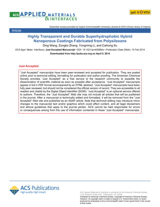
  • 6. 5 environmentally friendly. As illustrated in Figure 1, the solvent-free mixture of PSO and PDMS is spin-coated onto the substrate, followed by the catalyzed solidification of PSO, in which phase separation between PSO and PDMS takes place and the phase separation scale is easily controlled by the viscosity of the PDMS. The subsequent heat treatment transforms the solidified PSO into an organic−inorganic hybrid state, which is intrinsically hydrophobic because of the existence of Si−CHn units and more stable to heat, oxygen, and UV irradiation compared with polymeric materials. PDMS is decomposed and eliminated after the heat treatment, leading to the generation of nanoporous rough surfaces. This represents the first example of fabrication of highly transparent superhydrophobic coatings by phase-separation method without using expensive fluorinated reagents. The PSO-derived organic−inorganic hybrid material endows the coatings with good mechanical strength, relatively high thermal stability, and most importantly, durable superhydrophobicity. Moreover, the nanoscale surface roughness of the coating can be easily adjusted with this simple phase-separation method, and the high transparency does not rely on reducing the thickness of the coating. Page 5 of 30 ACS Paragon Plus Environment ACS Applied Materials & Interfaces 1 2 3 4 5 6 7 8 9 10 11 12 13 14 15 16 17 18 19 20 21 22 23 24 25 26 27 28 29 30 31 32 33 34 35 36 37 38 39 40 41 42 43 44 45 46 47 48 49 50 51 52 53 54 55 56 57 58 59 60
  • 7. 6 Figure 1. Schematic illustration of the fabrication procedures of the hybrid nanoporous coatings and the cross-linking formula of the platinum-catalyzed hydrosilylation reaction of Si−H and Si−CH=CH2 groups in the solidification process of PSO. 2. EXPERIMENTAL SECTION Polysiloxane (PSO) containing both Si−H and Si−CH=CH2 groups was used as the precursor. Methyl-terminated polydimethylsiloxanes (PDMS) (Hangping Chemical Co., Beijing, China) which decompose completely under 550 °C were used as porogens. The samples were denoted as C0, C1, C2, C3, C4, and C5 using PDMS with different viscosities (Table I) and were fabricated as follows. First, PSO and PDMS were mixed with a weight ratio of 15:85. Two ppm (weight ratio to the mixture of PSO and PDMS) of Karstedt’s catalyst (platinum- divinyltetramethyldisiloxane complex in divinyltetramethyldisiloxane; 1.5 wt % Pt; prepared by a standard procedure39 ) was subsequently added dropwise under vigorous stirring. After the addition, the mixture was continuously stirred for 30 min at room temperature. The as-prepared Page 6 of 30 ACS Paragon Plus Environment ACS Applied Materials & Interfaces 1 2 3 4 5 6 7 8 9 10 11 12 13 14 15 16 17 18 19 20 21 22 23 24 25 26 27 28 29 30 31 32 33 34 35 36 37 38 39 40 41 42 43 44 45 46 47 48 49 50 51 52 53 54 55 56 57 58 59 60
  • 8. 7 mixture (volume: 0.2 mL) was then spin-coated at 2000 rpm (acceleration: 2000 rpm s-1 ) for 40 s onto glass substrates and solidified in an oven at 120 °C for 6 h. Finally, the samples were heated at 550 °C for 1 h under an argon atmosphere in a Clock Hood-type furnace. The typical ramp rate was 2 °C min−1 at 20–250 °C and 0.5 °C min−1 at 250–550 °C. The chemical composition of the organic–inorganic hybrid material was examined by Fourier transform infrared spectroscopy (FTIR) (TENSOR 27, Bruker) and solid-state 29 Si and 13 C magic angle spinning (MAS) NMR (Avance III-400, Bruker) analyses. The microstructures of the coatings were observed with a scanning electron microscope (SEM) (S-4800, Hitachi) operated at 15 kV. The microdomain sizes of the coatings were estimated by software analysis (SMile View 2.1, JEOL) of the SEM images. The values reported were the averages of 50 measurements of different microdomains. The pore diameters, porosities and total pore areas of the coatings were determined by mercury pressure porosimetry (Pore Master 60GT, Quantachrome Instruments). The surface morphologies of the coatings were examined by atomic force microscopy (AFM) (Nanoscope IIIa, Digital Instruments). The surface roughnesses of the coatings were estimated by software analysis (Nanoscope Analysis 1.20, Veeco) of the AFM images. The water contact angles of the coatings were determined using a contact angle goniometer (DSA 100, Krüss) at ambient temperature. The volume of the water droplets was approximately 3 µL delivered using a micropipette for static contact angles (CA) and 10 µL delivered using the needle of the goniometer for slide angles (SA). The surface contact angle values reported were the averages of five measurements made on different areas of the coatings. The transmission spectra of the coatings in the range between 300 and 800 nm were recorded using a UV–vis spectrometer (U-3900, Hitachi) with a spectral resolution of 2 nm. The thermal behaviors of PDMS with different viscosities and the organic–inorganic hybrid material were Page 7 of 30 ACS Paragon Plus Environment ACS Applied Materials & Interfaces 1 2 3 4 5 6 7 8 9 10 11 12 13 14 15 16 17 18 19 20 21 22 23 24 25 26 27 28 29 30 31 32 33 34 35 36 37 38 39 40 41 42 43 44 45 46 47 48 49 50 51 52 53 54 55 56 57 58 59 60
  • 9. 8 investigated by thermogravimetric analysis (TGA) (TG/DTA6300, Seiko Instruments Inc.) with a heating rate of 10 °C min−1 . The TGA of PDMS were performed in argon from 50 to 800 °C, and the TGA of the hybrid material was performed in air from 50 to 500 °C. The mechanical stability of C2 and C3 was evaluated by the water drop test,19,20 in which 1500 water droplets (ca. 50 µL; impact velocity: 10 m s−1 , compression stress: 0.6 N) were dropped from a height of 5 m above the C2 and C3 coatings on glass substrate, respectively. The CAs, SAs, and transmission spectra of the coatings were measured after impact. 3. RESULTS AND DISCUSSION 3.1. Organic–Inorganic Hybrid Material The organic–inorganic hybrid material was derived from the polymer precursor PSO through two fabrication processes: solidification and heat treatment. The solidification process transforms PSO from a liquid linear polymer into a three-dimensional cross-linked network. The solidified PSO then forms an organic–inorganic hybrid material upon subsequent heat treatment at 550 °C. The FTIR spectra of PSO, solidified PSO, and the hybrid coating C0 are shown in Figure 2. In the FTIR curve of PSO, the absorption peaks at 2164 and 1599 cm−1 are the characteristic absorptions of the Si–H and Si–CH=CH2 groups, respectively. According to the cross-linking formula in Figure 1, the platinum-catalyzed hydrosilylation reaction in the solidification process consumes equal amounts of Si–H and Si–CH=CH2 groups, and the molar ratio of the two groups in PSO is 1.5:1; therefore, the Si–H groups in PSO are in excess. As a result, there is a weaker absorption peak of Si–H groups in the FTIR spectrum of solidified PSO (Figure 2). The remaining Si–H groups undergo Si–H/Si–O redistribution reactions at higher temperatures forming T (CSiO3) units and releasing gas according to the following equations:40,41 3DH → MeSiH3 + 2T, (1) Page 8 of 30 ACS Paragon Plus Environment ACS Applied Materials & Interfaces 1 2 3 4 5 6 7 8 9 10 11 12 13 14 15 16 17 18 19 20 21 22 23 24 25 26 27 28 29 30 31 32 33 34 35 36 37 38 39 40 41 42 43 44 45 46 47 48 49 50 51 52 53 54 55 56 57 58 59 60
  • 10. 9 4DH → (MeH2Si)2O + 2T, (2) where DH = CSi(H)O2 and T = CSiO3. Consequently, there is almost no absorption peak of Si–H groups in the FTIR spectrum of C0. During the polymer–ceramic transformation (i.e., the organic–inorganic transformation of PSO), the cleavage of C–H bonds usually starts at 600 °C.42 The peaks in the 2850–3000 cm−1 range and at 1265 cm−1 for C0 relate to the vibration of C–H in Si–CHn groups, indicating that the C–H bonds persist through heat treatment at 550 °C. The peaks in the 700–1250 cm−1 range of all curves are ascribed to the vibrations of the Si–O and Si– C bonds. The sharp and sophisticated peaks in PSO become two broad peaks in C0, signifying a relatively ordered Si–O–Si and Si–C–Si network in the organic–inorganic hybrid material. Figure 2. FTIR spectra of PSO, solidified PSO, and C0. Figure 3a shows the 29 Si MAS NMR spectra of solidified PSO and C0. The two main resonances in solidified PSO centered at −19 and −33 ppm can be assigned to D (C2SiO2) units, generated by cross-linking of Si–H and Si–CH=CH2 groups (Figure 1), and DH (C(H)SiO2) units, representing the excess Si–H groups, respectively. After heat treatment at 550 °C, the resonance of the DH units disappears, indicating the consumption of excess Si–H groups, which is in Page 9 of 30 ACS Paragon Plus Environment ACS Applied Materials & Interfaces 1 2 3 4 5 6 7 8 9 10 11 12 13 14 15 16 17 18 19 20 21 22 23 24 25 26 27 28 29 30 31 32 33 34 35 36 37 38 39 40 41 42 43 44 45 46 47 48 49 50 51 52 53 54 55 56 57 58 59 60
  • 11. 10 accordance with the FTIR results. Additionally, two new resonances appear in the C0 spectrum centered at 6 and −65 ppm, which can be assigned to M (C3SiO) and T (CSiO3) units, respectively. The T units confirm the aforementioned Si–H/Si–O redistribution reactions (eqs 1 and 2), and the M units provide evidence for the Si–O/Si–C redistribution reactions, which are the critical reactions in the high-temperature ceramization process of PSO.37 The equations are 2 D → M + T, (3) D + T → M + Q, (4) D + M → C + T, (5) D + Q → 2T, (6) where C = SiC4, M = C3SiO, D = C2SiO2, T = CSiO3, and Q = SiO4. The equilibrium of these reactions depends on the materials used and the processing temperature. It is shown in Figure 3a that the resonances of M, D, and T units are dominant in C0, which is an intermediate state between polymer and ceramic.43 Solidified PSO becomes organic–inorganic hybrid material through these redistribution reactions (eqs 1–6) which can further cross–link and strengthen the Si–O–Si and Si–C–Si network, leading to a relatively rigid structure of the final coatings. The 13 C MAS NMR spectrum of C0 is shown in Figure 3b. The resonance centered at 1.5 ppm is attributed to the carbon in the Si–CHn units, in agreement with the FTIR spectrum of C0. The FTIR and NMR results above verify that the organic–inorganic hybrid material contains Si–O, Si–C, and C–H bonds. The possible structure of the hybrid material is presented in Figure 4. The hydrophobic C–H bonds are the main reason for the intrinsic hydrophobicity of the hybrid material, which has a CA of 97.5° at the smooth C0 surface. Page 10 of 30 ACS Paragon Plus Environment ACS Applied Materials & Interfaces 1 2 3 4 5 6 7 8 9 10 11 12 13 14 15 16 17 18 19 20 21 22 23 24 25 26 27 28 29 30 31 32 33 34 35 36 37 38 39 40 41 42 43 44 45 46 47 48 49 50 51 52 53 54 55 56 57 58 59 60
  • 12. 11 Figure 3. (a) 29 Si MAS NMR spectra of solidified PSO and C0. (b) 13 C MAS NMR spectrum of C0. Page 11 of 30 ACS Paragon Plus Environment ACS Applied Materials & Interfaces 1 2 3 4 5 6 7 8 9 10 11 12 13 14 15 16 17 18 19 20 21 22 23 24 25 26 27 28 29 30 31 32 33 34 35 36 37 38 39 40 41 42 43 44 45 46 47 48 49 50 51 52 53 54 55 56 57 58 59 60
  • 13. 12 Figure 4. Possible structure of the organic–inorganic hybrid material. 3.2. Microstructure and Surface Morphology The SEM images of the hybrid coatings prepared using PDMS with different viscosities (Table I) are shown in Figure 5, together with that of C0 (fabricated without PDMS) for comparison. It can be observed from Figure 5 that C0 is very smooth and that all the other coatings have similar microstructures consisting of interconnected microdomains and nanopores. The development of the nanoporous microstructures is due to the phase separation between PSO and PDMS. Based on the similarity of the PSO and PDMS molecules (i.e., they both have Si–O–Si skeletons with Si–CH3 groups), they are compatible with each other in the mixture. During the solidification process of PSO, the cross-linking reaction of Si–H and Si–CH=CH2 groups gradually transforms the PSO through diffusion from a homogeneously dispersed linear polymer into interconnected solid microdomains. The porogen PDMS with higher viscosity directly lowers the diffusion rate of the catalyst and PSO molecules, and thereby reduces the cross-linking reaction rate of PSO and leads to greater phase separation. PDMS is then decomposed and eliminated by the heat Page 12 of 30 ACS Paragon Plus Environment ACS Applied Materials & Interfaces 1 2 3 4 5 6 7 8 9 10 11 12 13 14 15 16 17 18 19 20 21 22 23 24 25 26 27 28 29 30 31 32 33 34 35 36 37 38 39 40 41 42 43 44 45 46 47 48 49 50 51 52 53 54 55 56 57 58 59 60
  • 14. 13 treatment at 550 °C (Figure S1 of the Supporting Information), accompanied by a shrinkage about 5% of the thickness of the coating. Owing to the microdomains and nanopores between them, the surfaces of the coatings become rough, which can be seen from the AFM images in Figure 6. The nanoscale phase separation can be easily adjusted by changing the viscosity of the PDMS, resulting in tunable surface roughness of the coating. Figure 5. SEM images of the C0–C5 coatings. The microdomain sizes estimated from the SEM images and the average pore diameters determined by mercury pressure porosimetry are listed in Table I. (The microdomain size and Page 13 of 30 ACS Paragon Plus Environment ACS Applied Materials & Interfaces 1 2 3 4 5 6 7 8 9 10 11 12 13 14 15 16 17 18 19 20 21 22 23 24 25 26 27 28 29 30 31 32 33 34 35 36 37 38 39 40 41 42 43 44 45 46 47 48 49 50 51 52 53 54 55 56 57 58 59 60
  • 15. 14 pore diameter distributions are shown in Figure S2 and S3 of the Supporting Information.) The porosities and the total pore areas determined by mercury pressure porosimetry are listed in Table S1 of the Supporting Information to give more information concerning the nanoporous structure. The results in Table I confirm the influence of the viscosity of PDMS on the scale of the phase separation. With increasing viscosity of PDMS from 10 to 50 cP, the microdomain size increases from 32 to 52 nm and the average pore diameter increases from 23 to 141 nm, corresponding to an increasing larger scale of phase separation from C1 to C5. Accordingly, the total pore area of the coating decreases from 287.9 to 104.5 m2 g-1 based on similar porosities around 83% (Table S1). The root-mean-square (rms) roughness values, which represent the standard deviation of the roughness from the height obtained from software analysis of the AFM images, are also listed in Table I. This shows that C0 has a small rms roughness of 2.5 nm, which reflects a smooth surface. The rms roughness increases from 24.4 to 87.7 nm for C1–C5, which is the same variation tendency as the scale of phase separation. It is noted that the rms roughnesses are all below 100 nm. Such small values are sufficient to reduce the scattering of visible light, which is the reason for the high transparency of the coatings. Page 14 of 30 ACS Paragon Plus Environment ACS Applied Materials & Interfaces 1 2 3 4 5 6 7 8 9 10 11 12 13 14 15 16 17 18 19 20 21 22 23 24 25 26 27 28 29 30 31 32 33 34 35 36 37 38 39 40 41 42 43 44 45 46 47 48 49 50 51 52 53 54 55 56 57 58 59 60
  • 16. 15 Figure 6. AFM images of the C0–C5 coatings. Table I. The Influence of Different PDMS Viscosities on the Physical Properties of the C0–C5 Coatings. Page 15 of 30 ACS Paragon Plus Environment ACS Applied Materials & Interfaces 1 2 3 4 5 6 7 8 9 10 11 12 13 14 15 16 17 18 19 20 21 22 23 24 25 26 27 28 29 30 31 32 33 34 35 36 37 38 39 40 41 42 43 44 45 46 47 48 49 50 51 52 53 54 55 56 57 58 59 60
  • 17. 16 PDMS Viscosity (cP) Microdomain Size (nm) Average Pore Diameter (nm) Roughness (rmsα ) (nm) CA (º) SA (º) C0 —β — — 2.5 97.5 ± 2.2 Adhesion C1 10 32 ± 6 23 24.4 142.2 ± 2.7 Adhesion C2 15 37 ± 5 23 27.3 152.0 ± 0.5 < 1 C3 20 41 ± 1 45 30.6 155.0 ± 0.6 < 1 C4 30 47 ± 2 85 50.9 155.8 ± 1.4 < 1 C5 50 52 ± 2 141 87.7 155.9 ± 0.3 < 1 α rms, root-mean-square, which gives the standard deviation of the height values β —, not used or not determined 3.3. Hydrophobicity The water CAs and SAs of C0–C5 were investigated to examine the hydrophobicity of the coatings. The results are shown in Table I and Figure 7. The intrinsic CA of the smooth coating C0 is 97.5°, which is hydrophobic because of the composition of the hybrid material as demonstrated above. With increasing surface roughness from C1 to C5, the CA increases initially from 142.2° to 155.0° and then remains almost constant around 155°. The water droplets on C0 and C1 never roll off even when the glass slide is turned upside-down. The SAs of C2–C5 are all identified as less than 1° because the deposited water droplets slide off immediately after they are separated from the needle when the glass slide is tilted at an angle of 1° (Video S1 of the Supporting Information). Based on these results, C2–C5 are identified as superhydrophobic coatings. Page 16 of 30 ACS Paragon Plus Environment ACS Applied Materials & Interfaces 1 2 3 4 5 6 7 8 9 10 11 12 13 14 15 16 17 18 19 20 21 22 23 24 25 26 27 28 29 30 31 32 33 34 35 36 37 38 39 40 41 42 43 44 45 46 47 48 49 50 51 52 53 54 55 56 57 58 59 60
  • 18. 17 Figure 7. Water contact angles (CA) and slide angles (SA) of the C0–C5 coatings. The enhancement from hydrophobic to superhydrophobic with increasing surface roughness of the coatings can be explained by the transition from the Wenzel state to the Cassie state.44 According to the Wenzel model (eq I),45 the air entrapped in the voids of the substrate can be excluded by water droplets and a solid/liquid interface can form. The apparent Wenzel contact angle, θW , is defined as cos θW = r cos θ0, (I) where r is the roughness factor and defined as the ratio of true surface area to the horizontal projection of the surface area (r is larger than unity), and θ0 is the Young’s contact angle determined on a smooth surface of the same nature. Equation I predicts an increase of θW with increasing r when the substrate is intrinsically hydrophobic (θ0 > 90°). In contrast, in the Cassie model (eq II),46 water droplets are suspended beyond the air entrapped in the voids of the substrate and a solid/liquid/air composite interface forms. The apparent Cassie contact angle, θC , is defined as cos θC = f (cos θ0 + 1) − 1, (II) Page 17 of 30 ACS Paragon Plus Environment ACS Applied Materials & Interfaces 1 2 3 4 5 6 7 8 9 10 11 12 13 14 15 16 17 18 19 20 21 22 23 24 25 26 27 28 29 30 31 32 33 34 35 36 37 38 39 40 41 42 43 44 45 46 47 48 49 50 51 52 53 54 55 56 57 58 59 60
  • 19. 18 where f is the fraction of solid/liquid contact. Equation II predicts an increase of θC with decreasing solid/liquid contact in which increasingly more air is entrapped in the voids. In short, increasing surface roughness leads to increasing CA on Wenzel surfaces, but the surface roughness does not directly relate to the CA on Cassie surfaces. In addition, because of the decreased solid/liquid contact in the Cassie state, water droplets roll more easily on Cassie surfaces than on Wenzel surfaces, resulting in lower SAs.47–49 It is obvious from Figure 7 that the transition from the Wenzel state to the Cassie state takes place between C1 and C2. C0 and C1 are both in the Wenzel state. The higher surface roughness of C1 results in a higher CA of 142°. The adhesion of water droplets on C0 and C1 is due to the tight solid/liquid contact such that the adsorption force at the interface is higher than the gravitation force acting on the droplet when the glass slide is vertical. The superhydrophobic coatings C2−C5 are in the Cassie state. The fraction of solid/liquid contact in a solid/liquid/air composite interface is determined by many parameters of the surface morphology such as shape, size, height, and distribution of the microdomains.13,50 Therefore, the CA no longer increases with increasing rms roughness. According to eq II, the almost constant CA of 155° for C2−C5 implies a similar fraction of solid/liquid contact (ca. 10%), resulting in extremely low SAs because the water droplets almost float upon the air pockets within the rough surfaces. 3.4. Transparency Figure 8a shows the UV–vis transmission spectra of bare glass and the C0–C5 coatings on glass substrates. The transmittance decreases with increasing surface roughness from C0 to C5. However, the coatings are all transparent in the visible light wavelength range (400–780 nm), which is reflected in the easy readability of the letters underneath the coated glass slides even in the angled photograph (Figure 8b). Among the superhydrophobic coatings C2–C5, C2 has the Page 18 of 30 ACS Paragon Plus Environment ACS Applied Materials & Interfaces 1 2 3 4 5 6 7 8 9 10 11 12 13 14 15 16 17 18 19 20 21 22 23 24 25 26 27 28 29 30 31 32 33 34 35 36 37 38 39 40 41 42 43 44 45 46 47 48 49 50 51 52 53 54 55 56 57 58 59 60
  • 20. 19 highest average transmittance of 88.6%, very close to the value of bare glass (91.0%), in the visible light wavelength range. The C3 coating has a high CA of 155° and an average transmittance of 85.1%. It can be observed from the inset of Figure 8a that C0 has a slightly higher transmittance in the near-IR wavelength range, suggesting that the refractive index of the hybrid material is between that of air and glass, which could reduce reflection at the air/substrate interface and increase transparency. However, the main reason for the high transparency of the coatings is that the surface roughness of all surfaces is less than 100 nm—far from the minimum wavelength of visible light of 400 nm. Such nanoscale roughness could reduce the particle-size- dependent Mie scattering, resulting in higher transparency with lower surface roughness. In addition, as another parameter that affects transparency, the thickness of the coatings in this work is between 2 and 7 µm (Figure S4 of the Supporting Information). In other words, the high transparency of the coatings does not rely on the thinness. Page 19 of 30 ACS Paragon Plus Environment ACS Applied Materials & Interfaces 1 2 3 4 5 6 7 8 9 10 11 12 13 14 15 16 17 18 19 20 21 22 23 24 25 26 27 28 29 30 31 32 33 34 35 36 37 38 39 40 41 42 43 44 45 46 47 48 49 50 51 52 53 54 55 56 57 58 59 60
  • 21. 20 Figure 8. (a) UV–vis transmission spectra of bare glass and the C0–C5 coatings. The inset shows the magnified curves of bare glass and C0. (b) Angled (upper) and front (lower) photographs of bare glass and the C1–C5 coatings. 3.5. Thermal and Mechanical Stability, and Durable Superhydrophobicity The organic–inorganic hybrid material is relatively more stable toward heat and oxygen compared with polymeric materials. There is no weight loss in the TGA curve of the hybrid material (Figure S5 of the Supporting Information) up to 300 °C in air. The CA and SA of C3 remain unchanged after heat treatment at 400 °C for 1 h in air at 155.0° and less than 1°, respectively. The good stability toward heat and oxygen makes this material applicable in high- temperature processes where polymeric materials might melt. One of the problems for the Page 20 of 30 ACS Paragon Plus Environment ACS Applied Materials & Interfaces 1 2 3 4 5 6 7 8 9 10 11 12 13 14 15 16 17 18 19 20 21 22 23 24 25 26 27 28 29 30 31 32 33 34 35 36 37 38 39 40 41 42 43 44 45 46 47 48 49 50 51 52 53 54 55 56 57 58 59 60
  • 22. 21 practical application of superhydrophobic surfaces is that the elaborately designed microstructures of the rough surfaces are easily damaged due to their weak mechanical strength. However, the nanoporous structure extends through the entire thickness of the coating (Figure S4 of the Supporting Information); therefore, the surface of the coating remains nanoporous and superhydrophobic even if the top layer of the coating has been scraped off. Besides, the bonding of the coatings with the glass substrate is good, because peeling off adhesive tapes (3M Scotch Cellophane Film Tape 610, pressed with approximately 10kPa to the coatings) does not remove the coating on the area underneath. The mechanical stability of C2 and C3 on glass substrate was examined by the water drop test, in which about 1500 water droplets (ca. 50 µL, impacting velocity: 10 m s−1 , compression stress: 0.6 N) are dropped from a height of 5 m above the coating. The CAs, SAs, and average transmittances in the visible light wavelength range of the coatings before and after impact were listed in Table II. (The transmission spectra are shown in Figure S6 of the Supporting Information.) The superhydrophobicity and transparency of water rinsed coatings almost remained unchanged, reflecting their good mechanical strength. Table II. Comparison of the Superhydrophobicity and Transparency of the Coatings C2 and C3 Before and After the Water Drop Test. CA (º) SA (º) Average Transmittanceα (%) C2 152.0 ± 0.5 < 1 88.6 C2 after impact 152.3 ± 0.6 < 1 88.8 C3 155.0 ± 0.6 < 1 85.1 C3 after impact 155.1 ± 0.2 < 1 85.0 α in the visible light wavelength range: 400–780 nm Another important requirement for real applications is the durability of superhydrophobicity. The CA and SA of the C3 were measured every two weeks after storage under ambient Page 21 of 30 ACS Paragon Plus Environment ACS Applied Materials & Interfaces 1 2 3 4 5 6 7 8 9 10 11 12 13 14 15 16 17 18 19 20 21 22 23 24 25 26 27 28 29 30 31 32 33 34 35 36 37 38 39 40 41 42 43 44 45 46 47 48 49 50 51 52 53 54 55 56 57 58 59 60
  • 23. 22 conditions beside the window. The superhydrophobicity of the coating remained excellent with no change of CA and SA for five months. The durable superhydrophobicity results from the chemical composition of the organic–inorganic hybrid material (Figure 4). This material has almost no active sites that form hydrogen bonds or hydrogen bonding active groups that can undergo hydration.51 4. CONCLUSIONS A simple and inexpensive solidification-induced phase-separation method has been applied to fabricate highly transparent and durable superhydrophobic (CA: 155°, SA: < 1°) organic– inorganic hybrid nanoporous coatings using a liquid PSO as the precursor and PDMS as porogens. This is the first time that highly transparent and superhydrophobic coatings have been fabricated by phase-separation method without using expensive fluorinated reagents. The method can easily provide nanoscale surface roughness using intrinsically hydrophobic hybrid material to fulfill the requirements of both high transparency and superhydrophobicity. The influence of surface roughness on the transparency and hydrophobicity of the coatings was investigated. The coating changed from the Wenzel state to the Cassie state and from hydrophobicity to superhydrophobicity with increasing surface roughness. The transparency of the coating decreased with increasing surface roughness; however, the coatings were all transparent mainly because the surface roughnesses were below 100 nm. It must be emphasized that the PSO- derived organic–inorganic hybrid material endowed the coatings with good stability toward heat and oxygen, and that the excellent superhydrophobicity lasted for more than five months. The shortcoming of the current method is the relatively high temperature for heat treatment. Further studies on the selection of porogens with lower decomposition temperature are ongoing in our laboratory. The simple and economical fabrication process, high transparency, durable Page 22 of 30 ACS Paragon Plus Environment ACS Applied Materials & Interfaces 1 2 3 4 5 6 7 8 9 10 11 12 13 14 15 16 17 18 19 20 21 22 23 24 25 26 27 28 29 30 31 32 33 34 35 36 37 38 39 40 41 42 43 44 45 46 47 48 49 50 51 52 53 54 55 56 57 58 59 60
  • 24. 23 hydrophobicity, and good thermal and mechanical stability of the coatings highlight their potential in practical applications such as safety goggles, windshields, solar cell panels, and windows for electronic devices. ASSOCIATED CONTENT Supporting Information Video of water droplets rolling off the superhydrophobic surface of C3. TGA curves of PDMS with different viscosities in argon with a heating rate of 10 ºC min–1 from 50 to 800 ºC. The microdomain size distributions, pore diameter distributions, porosities, and total pore areas of the coatings C1–C5. SEM images of the cross sections of the coatings C1–C5. TGA curve of the hybrid material in air with a heating rate of 10 °C min−1 from 50 to 500 °C. UV–vis transmission spectra of C2 and C3 after the water drop test. This material is available free of charge via the Internet at http://pubs.acs.org. AUTHOR INFORMATION Corresponding Author *Tel.: +86-10-62554487. Fax: +86-10-62554487. E-mail: lym018@iccas.ac.cn (L.Y.); caihong@iccas.ac.cn (X.C.). Funding Sources National Natural Science Foundation of China (51273205), Ministry of Science and Technology of China (2010CB934705, 2012CB933200) Notes The authors declare no competing financial interest. Page 23 of 30 ACS Paragon Plus Environment ACS Applied Materials & Interfaces 1 2 3 4 5 6 7 8 9 10 11 12 13 14 15 16 17 18 19 20 21 22 23 24 25 26 27 28 29 30 31 32 33 34 35 36 37 38 39 40 41 42 43 44 45 46 47 48 49 50 51 52 53 54 55 56 57 58 59 60
  • 25. 24 ACKNOWLEDGMENT The authors acknowledge the financial support from the National Natural Science Foundation of China (51273205), Ministry of Science and Technology of China (2010CB934705, 2012CB933200). REFERENCES (1) Kako, T.; Nakajima, A.; Irie, H.; Kato, Z.; Uematsu, K.; Watanabe, T.; Hashimoto, K. Adhesion and Sliding of Wet Snow on a Super-Hydrophobic Surface with Hydrophilic Channels J. Mater. Sci 2004, 39, 547–555. (2) Zielecka, M.; Bujnowska, E. Silicone-Containing Polymer Matrices as Protective Coatings: Properties and Applications Prog. Org. Coat. 2006, 55, 160–167. (3) Mahltig, B.; Böttcher, H. Modified Silica Sol Coatings for Water-Repellent Textiles J. Sol- Gel Sci. Technol. 2003, 27, 43–52. (4) Zhang, H.; Lamb, R.; Lewis, J. Engineering Nanoscale Roughness on Hydrophobic Surface —Preliminary Assessment of Fouling Behaviour Sci. Technol. Adv. Mater. 2005, 6, 236–239. (5) Choi, S. J.; Huh, S. Y. Direct Structuring of a Biomimetic Anti-Reflective, Self-Cleaning Surface for Light Harvesting in Organic Solar Cells Macromol. Rapid Commun. 2010, 31, 539– 544. (6) Tadanaga, K.; Katata, N.; Minami, T. Super-Water-Repellent Al2O3 Coating Films with High Transparency J. Am. Ceram. Soc. 1997, 80, 1040–1042. Page 24 of 30 ACS Paragon Plus Environment ACS Applied Materials & Interfaces 1 2 3 4 5 6 7 8 9 10 11 12 13 14 15 16 17 18 19 20 21 22 23 24 25 26 27 28 29 30 31 32 33 34 35 36 37 38 39 40 41 42 43 44 45 46 47 48 49 50 51 52 53 54 55 56 57 58 59 60
  • 26. 25 (7) Lee, S. G.; Lee, D. Y.; Lim, H. S.; Lee, D. H.; Lee, S.; Cho, K. Switchable Transparency and Wetting of Elastomeric Smart Windows Adv. Mater. 2010, 22, 5013–5017. (8) Sun, T.; Feng, L.; Gao, X.; Jiang, L. Bioinspired Surfaces with Special Wettability Acc. Chem. Res. 2005, 38, 644–652. (9) Zhang, X.; Shi, F.; Niu, J.; Jiang, Y.; Wang, Z. Superhydrophobic Surfaces: From Structural Control to Functional Application J. Mater. Chem. 2008, 18, 621–633. (10) Song, X.; Zhai, J.; Wang, Y.; Jiang, L. Fabrication of Superhydrophobic Surfaces by Self- Assembly and Their Water-Adhesion Properties J. Phys. Chem. B 2005, 109, 4048–4052. (11) Qian, B.; Shen, Z. Fabrication of Superhydrophobic Surfaces by Dislocation-Selective Chemical Etching on Aluminum, Copper, and Zinc Substrates Langmuir 2005, 21, 9007–9009. (12) Her, E. K.; Ko, T. J.; Shin, B.; Roh, H.; Dai, W.; Seong, W. K.; Kim, H. Y.; Lee, K. R.; Oh, K. H.; Moon, M. W. Superhydrophobic Transparent Surface of Nanostructured Poly(Methyl Methacrylate) Enhanced by a Hydrolysis Reaction Plasma Processes Polym. 2013, 10, 481–488. (13) Öner, D.; McCarthy, T., Jr. Ultrahydrophobic Surfaces. Effects of Topography Length Scales on Wettability Langmuir 2000, 16, 7777–7782. (14) Shirtcliffe, N. J.; McHale, G.; Newton, M. I.; Chabrol, G.; Perry, C. C. Dual-Scale Roughness Produces Unusually Water-Repellent Surfaces Adv. Mater. 2004, 16, 1929–1932. (15) Tavana, H.; Amirfazli, A.; Neumann, A. W. Fabrication of Superhydrophobic Surfaces of n-Hexatriacontane Langmuir 2006, 22, 5556–5559. Page 25 of 30 ACS Paragon Plus Environment ACS Applied Materials & Interfaces 1 2 3 4 5 6 7 8 9 10 11 12 13 14 15 16 17 18 19 20 21 22 23 24 25 26 27 28 29 30 31 32 33 34 35 36 37 38 39 40 41 42 43 44 45 46 47 48 49 50 51 52 53 54 55 56 57 58 59 60
  • 27. 26 (16) Lau, K. K. S.; Bico, J.; Teo, K. B. K.; Chhowalla, M.; Amaratunga, G. A. J.; Milne, W. I.; McKinley, G. H.; Gleason, K. K. Superhydrophobic Carbon Nanotube Forests Nano Lett. 2003, 3, 1701–1705. (17) Park, S. H.; Lee, S. M.; Lim, H. S.; Han, J. T.; Lee, D. R.; Shin, H. S.; Jeong, Y.; Kim, J.; Cho, J. H. Robust Superhydrophobic Mats Based on Electrospun Crystalline Nanofibers Combined with a Silane Precursor ACS Appl. Mater. Interfaces 2010, 2, 658–662. (18) Ma, M.; Hill, R. M.; Lowery, J. L.; Fridrikh, S. V.; Rutledge, G. C. Electrospun Poly(Styrene-block-dimethylsiloxane) Block Copolymer Fibers Exhibiting Superhydrophobicity Langmuir 2005, 21, 5549–5554. (19) Gao, L.; He, J. Surface Hydrophobic Co-Modification of Hollow Silica Nanoparticles toward Large-Area Transparent Superhydrophobic Coatings J. Colloid Interface Sci. 2013, 396, 152–159. (20) Xu, L.; Karunakaran, R. G.; Guo, J.; Yang, S. Transparent, Superhydrophobic Surfaces from One-Step Spin Coating of Hydrophobic Nanoparticles ACS Appl. Mater. Interfaces 2012, 4, 1118–1125. (21) Du, X.; Li, X.; He, J. Facile Fabrication of Hierarchically Structured Silica Coatings from Hierarchically Mesoporous Silica Nanoparticles and Their Excellent Superhydrophilicity and Superhydrophobicity ACS Appl. Mater. Interfaces 2010, 2, 2365–2372. (22) Xu, Q. F.; Liu, Y.; Lin, F. J.; Mondal, B.; Lyons, A. M. Superhydrophobic TiO2–Polymer Nanocomposite Surface with UV-Induced Reversible Wettability and Self-Cleaning Properties ACS Appl. Mater. Interfaces 2013, 5, 8915–8924. Page 26 of 30 ACS Paragon Plus Environment ACS Applied Materials & Interfaces 1 2 3 4 5 6 7 8 9 10 11 12 13 14 15 16 17 18 19 20 21 22 23 24 25 26 27 28 29 30 31 32 33 34 35 36 37 38 39 40 41 42 43 44 45 46 47 48 49 50 51 52 53 54 55 56 57 58 59 60
  • 28. 27 (23) Deng, X.; Mammen, L.; Butt, H. J.; Vollmer, D. Candle Soot as a Template for a Transparent Robust Superamphiphobic Coating Science 2012, 335, 67–70. (24) Shang, H. M.; Wang, Y.; Limmer, S. J.; Chou, T. P.; Takahashi, K.; Cao, G. Z. Optically Transparent Superhydrophobic Silica-Based Films Thin Solid Films 2005, 472, 37–43. (25) Tadanaga, K.; Kitamuro, K.; Matsuda, A.; Minami, T. Formation of Superhydrophobic Alumina Coating Films with High Transparency on Polymer Substrates by the Sol-Gel Method J. Sol-Gel Sci. Technol. 2003, 26, 705–708. (26) Du, X.; Li, J. S.; Li, L. X.; Levkin, P. A. Porous Poly(2-Octyl Cyanoacrylate): A Facile One-Step Preparation of Superhydrophobic Coatings on Different Substrates J. Mater. Chem. A 2013, 1, 1026–1029. (27) Erbil, H. Y.; Demirel, A. L.; Avci, Y.; Mert, O. Transformation of a Simple Plastic into a Superhydrophobic Surface Science 2003, 299, 1377–1380. (28) Zhao, N.; Xie, Q.; Weng, L.; Wang, S.; Zhang, X.; Xu, J. Superhydrophobic Surface from Vapor-Induced Phase Separation of Copolymer Micellar Solution Macromolecules 2005, 38, 8996–8999. (29) Xie, Q.; Xu, J.; Feng, L.; Jiang, L.; Tang, W.; Luo, X.; Han, C. C. Facile Creation of a Super-Amphiphobic Coating Surface with Bionic Microstructure Adv. Mater. 2004, 16, 302– 305. (30) Kato, S.; Sato, A. Micro/Nanotextured Polymer Coatings Fabricated by UV Curing- Induced Phase Separation: Creation of Superhydrophobic Surfaces J. Mater. Chem. 2012, 22, 8613–8621. Page 27 of 30 ACS Paragon Plus Environment ACS Applied Materials & Interfaces 1 2 3 4 5 6 7 8 9 10 11 12 13 14 15 16 17 18 19 20 21 22 23 24 25 26 27 28 29 30 31 32 33 34 35 36 37 38 39 40 41 42 43 44 45 46 47 48 49 50 51 52 53 54 55 56 57 58 59 60
  • 29. 28 (31) Nakajima, A.; Fujishima, A.; Hashimoto, K.; Watanabe, T. Preparation of Transparent Superhydrophobic Boehmite and Silica Films by Sublimation of Aluminum Acetylacetonate Adv. Mater. 1999, 11, 1365–1368. (32) Levkin, P. A.; Svec, F.; Frechet, J. M. Porous Polymer Coatings: A Versatile Approach to Superhydrophobic Surfaces Adv. Funct. Mater. 2009, 19, 1993–1998. (33) Wu, J.; Li, Y.; Chen, L.; Zhang, Z.; Wang, D.; Xu, C. Simple Fabrication of Micro/Nano- Porous SiOC Foam from Polysiloxane J. Mater. Chem. 2012, 22, 6542–6545. (34) Inoue, T. Reaction-Induced Phase Decomposition in Polymer Blends Prog. Polym. Sci. 1995, 20, 119–153. (35) Meng, F.; Zheng, S.; Li, H.; Liang, Q.; Liu, T. Formation of Ordered Nanostructures in Epoxy Thermosets:  A Mechanism of Reaction-Induced Microphase Separation Macromolecules 2006, 39, 5072–5080. (36) Lipatov, Y. S.; Kosyanchuk, L. F.; Nesterov, A. F. Phase Separation in Blends of Linear Polymers Formed in Situ According to Different Mechanisms Polym. Int. 2002, 51, 772–780. (37) Park, J. W.; Kim, S. C. Phase Separation During Synthesis of Polyetherimide/Epoxy Semi-IPNs Polym. Adv. Technol. 1996, 7, 209–220. (38) Girard-Reydet, E.; Sautereau, H.; Pascault, J. P.; Keates, P.; Navard, P.; Thollet, G.; Vigier, G. Reaction-Induced Phase Separation Mechanisms in Modified Thermosets Polymer 1998, 39, 2269–2279. (39) Karstedt, B. D.; Scotia, N. Y. Platinum-Vinylsiloxanes. U.S. Patent 3,715,334, Feburary 6, 1973. Page 28 of 30 ACS Paragon Plus Environment ACS Applied Materials & Interfaces 1 2 3 4 5 6 7 8 9 10 11 12 13 14 15 16 17 18 19 20 21 22 23 24 25 26 27 28 29 30 31 32 33 34 35 36 37 38 39 40 41 42 43 44 45 46 47 48 49 50 51 52 53 54 55 56 57 58 59 60
  • 30. 29 (40) Gualandris, V.; Hourlier-Bahloul, D.; Babonneau, F. Structural Investigation of the First Stages of Pyrolysis of Si-C-O Preceramic Polymers Containing Si–H Bonds J. Sol-Gel Sci. Technol. 1999, 14, 39–48. (41) Belot, V.; Corriu, R. J. P.; Leclercq, D.; Mutin, P. H.; Vioux, A. Redistribution Reactions in Silsesquioxane Gels J. Mater. Sci. Lett. 1990, 9, 1052–1054. (42) Radovanovic, E.; Gozzi, M. F.; Gonçalves, M. C.; Yoshida, I. V. P. Silicon Oxycarbide Glasses from Silicone Networks J. Non-Cryst. Solids 1999, 248, 37–48. (43) Schiavon, M. A.; Radovanovic, E.; Yoshida, I. V. P. Microstructural Characterisation of Monolithic Ceramic Matrix Composites from Polysiloxane and SiC Powder Powder Technol. 2002, 123, 232–241. (44) Johnson, R. E., Jr.; Dettre, R. H. Contact Angle Hysteresis I. Study of an Idealized Rough Surface Adv. Chem. Ser. 1964, 43, 112–135. (45) Wenzel, R. N. Resistance of Solid Surfaces to Wetting by Water Ind. Eng. Chem. 1936, 28, 988–994. (46) Cassie, A. B. D.; Baxter, S. Wettability of Porous Surfaces Trans. Faraday Soc. 1944, 40, 546–551. (47) Lafuma, A.; Quere, D. Superhydrophobic States Nat. Mater. 2003, 2, 457–460. (48) McHale, G.; Shirtcliffe, N. J.; Newton, M. I. Contact-Angle Hysteresis on Super- Hydrophobic Surfaces Langmuir 2004, 20, 10146–10149. Page 29 of 30 ACS Paragon Plus Environment ACS Applied Materials & Interfaces 1 2 3 4 5 6 7 8 9 10 11 12 13 14 15 16 17 18 19 20 21 22 23 24 25 26 27 28 29 30 31 32 33 34 35 36 37 38 39 40 41 42 43 44 45 46 47 48 49 50 51 52 53 54 55 56 57 58 59 60
  • 31. 30 (49) Pilotek, S.; Schmidt, H. K. Wettability of Microstructured Hydrophobic Sol-Gel Coatings J. Sol-Gel Sci. Technol. 2003, 26, 789–792. (50) Li, W.; Amirfazli, A. Microtextured Superhydrophobic Surfaces: A Thermodynamic Analysis Adv. Colloid Interface Sci. 2007, 132, 51–68. (51) Boinovich, L.; Emelyanenko, A. M.; Pashinin, A. S. Analysis of Long-Term Durability of Superhydrophobic Properties under Continuous Contact with Water ACS Appl. Mater. Interfaces 2010, 2, 1754–1758. SYNOPSIS Page 30 of 30 ACS Paragon Plus Environment ACS Applied Materials & Interfaces 1 2 3 4 5 6 7 8 9 10 11 12 13 14 15 16 17 18 19 20 21 22 23 24 25 26 27 28 29 30 31 32 33 34 35 36 37 38 39 40 41 42 43 44 45 46 47 48 49 50 51 52 53 54 55 56 57 58 59 60