
Recommended
More Related Content
Similar to Introduction to MOS Technology.pdf
Similar to Introduction to MOS Technology.pdf (20)
Recently uploaded
Recently uploaded (20)
Introduction to MOS Technology.pdf
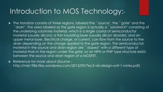
- 1. Introduction to MOS Technology:- The transistor consists of three regions, labeled the ``source'', the ``gate'' and the ``drain''. The area labeled as the gate region is actually a ``sandwich'' consisting of the underlying substrate material, which is a single crystal of semiconductor material (usually silicon); a thin insulating layer (usually silicon dioxide); and an upper metal layer. Electrical charge, or current, can flow from the source to the drain depending on the charge applied to the gate region. The semiconductor material in the source and drain region are ``doped'' with a different type of material than in the region under the gate, so an NPN or PNP type structure exists between the source and drain region of a MOSFET. Reference for more about-(Source : http://msk1986.files.wordpress.com/2013/09/7ec5-vlsi-design-unit-1-notes.pdf)
- 2. CMOS Inverter : Working & Its Applications CMOS” stands for “complementary-symmetry metal–oxide–semiconductor” which is pronounced as “see mos”. CMOS is a type of MOSFET, where its fabrication process uses complementary & symmetrical P-type & N-type MOSFET pairs for logic functions. The main CMOS devices characteristics are consumption of low static power & high noise immunity. The inverter is accepted universally as the basic logic gate while performing a Boolean operation on a single i/p variable. A basic inverter circuit is used to accomplish a logic variable by complementing from A to A’. So, a CMOS inverter is a very simple circuit, designed with two opposite-polarity MOSFETs within a complementary way.
- 3. CMOS Inverter:- CMOS inverter definition is a device that is used to generate logic functions is known as CMOS inverter and is the essential component in all integrated circuits. A CMOS inverter is a FET (field effect transistor), composed of a metal gate that lies on top of oxygen’s insulating layer on top of a semiconductor. These inverters are used in most electronic devices which are accountable for generating data n small circuits.
- 4. CMOS Inverter Schematic Diagram:- The logic element like an inverter reverses the applied input signal. In digital logic circuits, binary arithmetic & switching or logic function’s mathematical manipulation are best performed through the symbols 0 & 1. The CMOS inverter truth table is shown above. If the input logic is zero (0) then the output will be high (1) whereas, if the input logic is one (1), then the output will be low (0) The general CMOS inverter structure is the combination of both the PMOS & NMOS transistors where the pMOS is arranged at the top & nMOS is arranged at the bottom.
- 5. The connection of both the PMOS & NMOS transistors in the CMOS inverter can be done like this. The NMOS transistor is connected at the drain (D) & gate (G) terminals, a voltage supply (VDD) is connected at the source terminal of PMOS & a GND terminal is connected at the source terminal of NMOS. Input voltage (Vin) is connected to both the gate terminals of transistors & output voltage (Vout) is connected to the drain (D) terminals of the transistor. It is very significant to observe that the CMOS device does not have any resistors, so it will be more power-efficient. Once the input voltage of CMOS changes between 0 to 5 volts, then both the transistors state will be changed accordingly. If we design every transistor like a simple switch that is operated through input voltage (Vin), then operations of the inverter can be observed very simply:
- 7. CMOS Inverter Operation & Working:- The working of CMOS inverter is the same as other types of FETs except depends on an oxygen layer to divide electrons within the gate & semiconductor. They are designed with a power supply, input voltage terminal, output voltage, gate, drain, and PMOS & NMOS transistors which are connected to the gate & the drain terminals. When the low input voltage is given to the CMOS inverter, then the PMOS transistor is switched ON whereas the NMOS transistor will switch OFF by allowing the flow of electrons throughout the gate terminal & generating high logic output voltage. Similarly, when the high input voltage is given to the CMOS inverter then, the PMOS transistor is switched OFF whereas the NMOS transistor will be switched ON avoiding as many electrons from attaining the output voltage & generating low logic output voltage. Thus, direct current supplies from the supply voltage (VDD) to the output voltage (Vout) & the load capacitor (CL) can be charged and shows that Vout = VDD. As a result, the above circuit works like an inverter.
- 8. CMOS Inverter Characteristics:- Inverter Static Characteristics or VTC:-The quality of the inverter can be measured frequently by using the VTC or voltage transfer curve, which is plotted between input voltage (Vin) and output voltage (Vo). From the following static characteristics, the parameters of devices like gain, operating logic levels & noise tolerance, and noise can be obtained. The quality of the inverter can be measured frequently by using the VTC or voltage transfer curve, which is plotted between input voltage (Vin) and output voltage (Vo). From the following static characteristics, the parameters of devices like gain, operating logic levels & noise tolerance, and noise can be obtained.
- 9. Inverter Dynamic Characteristics The CMOS inverter dynamic characteristics are shown below. So, some of the following formal definitions of different parameters are discussed below. Here, all the percentage (%) values are the steady-state values. • Rise Time or tr: Rise time is the time used to increase the signal from 10% to 90%. • Fall Time or tf: Fall time is the time used to drop the signal from 90% to 10% • Edge Rate or trf : It is (tr + tf )/2. • The propagation delay from high to low or tpHL: The time used to drop from VOH – 50%. • The propagation delay from low to high or tpLH: The time used to increase from 50%- VOL. • Propagation Delay or tp: It is (tpHL + tpLH)/2. • Contamination Delay or tcd: It is the smallest time from the 50% input crossing to the 50% output crossing.
- 10. Advantages The CMOS inverter advantages include the following. • The CMOS inverter’s steady-state power dissipation is negligible virtually, apart from small power dissipation because of leakage currents. • The VTC (voltage transfer characteristic) exhibits a complete o/p voltage swing in between 0 V & VDD, and the transition of voltage transfer characteristic is normally very sharp. Thus, the characteristics of the CMOS inverter look like an ideal inverter. • These inverters use electricity once they are switched ON & OFF resulting in less power consumption. As a result, these inverters generate extremely less waste heat to make them highly efficient, so used in small and delicate electronic devices. • These inverters include high noise immunity, which lets them block both incoming & outgoing frequency spikes. • These are low-cost to produce mass. Disadvantages The CMOS inverter disadvantages include the following. • As compared to other inverters, the switching speed of the CMOS inverter is high. • These are very difficult to fabricate due to both the transistors used on the same Silica piece. • It uses two transistors to make an inverter, so it uses more space on the IC as compared to the NMOS inverter.
- 11. Applications The applications of CMOS inverters include the following. • CMOS inverters are used in different ICs (integrated circuits) like microprocessors, static RAM, microcontrollers, data converters, image sensors & transceivers. • These are found in mobile devices, digital cameras, home computers, cell phones, routers, network servers, modems & virtually each other electronic device that needs logic functions.
- 12. CMOS Inverter: Propagation Delay A. Introduction • Propagation delays t PHL and tPLH define ultimate speed of logic • Define Average Propagation Delay tp=( t PHL+ t PLH )/ 2 • Typical complex system has 20-50 propagation delays per clock cycle. • Typical propagation delays < 1nse