SlideShare a Scribd company logo
1 of 29
Download to read offline
META-MATERIALS
●The materials having properties of manipulating electromagnetic waves: by
blocking, absorbing, enhancing, bending waves, to achieve benefits that go
beyond what is possible with conventional materials.
●In the following picture, Ring resonator is the basic repeating unit used.
●The Split ring resonators require an external time-varying magnetic field
applied parallel to the particle axis induces rotating currents in the rings, which
produces SRR’s own flux to enhance or oppose the incident field.
Split Ring Resonator
●SRR behaves as an LC resonant tank consisting of capacitance between
concentric rings and overall rings inductance.
●At frequencies below the resonant frequency, the real part of magnetic
permeability of SRR becomes large (positive) and goes to negative values at
frequencies higher than the resonant one.
●Transmission does not occur: stop-band at opposite values of µ & ε. And vise-
versa.
INTRODUCTION to LC
●Definition: Meta-materials with simultaneously negative permittivity (ε) and
permeability (µ), more commonly referred to as left-handed (LH) materials.
●The combined circuit representation is “composite right left handed” viz. CRLH
●Dual nature of the CRLH TL : At low frequencies the CRLH TL is dominantly LH,
while at high frequencies the CRLH Tl is dominantly RH
●In reality, a PLH structure is not possible because of unavoidable RH parasitic series
inductance (L) and shunt capacitance (C) effects.
IMPORTANT TERMS
●The propagation constant γ = α+ jβ =√(Z*Y),
●where, α = attenuation constant;
● per-unit length impedance Z(ω) = j [ωLR− 1/ωCL]
● per-unit length admittance Y(ω) = j [ωCR− 1/ωLL]
●Phase constant β is given as: β = ω√µε,
Derivation of this formula on slide 12
How is CRLH implemented?
 The CRLH has either a
negative permittivity (−ε)
or negative permeability
(−μ) in its stop-band
.
 By combining a −ε CRLH
TL with a −μ, CRLH TL, a
resonator independent of
physical length similar to
the Zeroth Order
Resonator is obtained.
IMPORTANT TERMS
●The characteristic impedance of a TL is given by Zo =√Z/Y. For the CRLH TL,
the characteristic impedance is
●where
●The expressions of µ and ε from β and Zo;
The β is real in pass band, as expressed in the dispersion diagrams ω vs β, below;
Figure (c) illustrates the stop-band that occurs when γ is purely real, β being zero, for a CRLH TL
REALIZATION OF THE GRAPH: By the relation (n=cβ/ω), at ω0, the phase shift for a TL
of length d is zero (φ =−βd=0). (φ>0) occurs in the LH frequency range (ω<ω0)
and (φ<0) occurs in the RH frequency range (ω>ω 0).
As it will be explained later, the low-
pass and high pass stop bands of RH
and LH materials are obtained at
upper and lower parts of the graph.
Higher ω => Low pass center of RH
Lower ω=> High pass center of LH
This is an interpretation of equations of lossless case.
THEORY
Extracting the information from the previous figure, we observe that:
 When β is purely real, a pass-band is present since γ = jβ.
 β is purely imaginary since γ = α, stop-band occurs.
 This stop-band is a unique characteristic of the CRLH TL, which is not
present in the PRH or the PLH cases.
●Resonance and its importance:
 The series and shunt resonances of the CRLH TL are different. It requires
contribution from LH TL and RH TL both. This is called the unbalanced case.
However, when the series and shunt resonances are equal.
 LRCL =LLCR; the LH and RH contribution exactly balance each other at
frequency ω0. It is important to determine the stop band frequency at which
the TL transition occurs.
THEORY
●The balanced graph: An LH to RH transition occurs at transition
●frequency ω0 ->Unbalanced =1/4* √(LRCRLCL)
● balanced =1 √LC
There is a continuous transition from LH to RH for the balanced case, because γ is
always purely imaginary, unlike the unbalanced case. the balanced CRLH TL’s
dispersion curve does not have a stop-band.
Continued...
 The group velocity (vg = ∂ω/∂β) and phase velocity (vp = ω/β) of these TLs
can be inferred from the dispersion diagram.
 These diagrams show that vg and vp for a PRH TL are parallel (vgvp > 0),
while vg and vp for a PLH TL are antiparallel (vgvp < 0).
 In addition, the CRLH TL’s dispersion diagram shows that it has an LH
(vg.vp < 0) and RH (vg.vp > 0) region.
The 2-D CRLH TL supports wave propagation in any direction within the
structure. As a result, the phase constant β is a vector quantity for the 2-D CRLH
TL,
−β(→) =xkx +yky
where kx and ky are the propagation constants for the x and y directions. By
applying PBCs to the 2-D unit cell along the x and y directions, the 2-D
dispersion relation
This relation reduces to as given in next slide:
By applying periodic boundary conditions (PBCs) related to the Bloch-Floquet
theorem to the LC unit cell, LC dispersion relation:
Since the electrical length of the unit cell is small, the Taylor approximation
cos(βp) ≈ 1 − (βp)2/2 can be applied and it becomes
which is identical to the homogeneous dispersion relation of (2) (with LR= LR/p,CR=
CR/p, LL=LLp,CL= CLp).
Thus the LC-based CRLH TL is equivalent to the homogeneous CRLH TL for small
electrical lengths.
Difference: filter and CRLH meta-mat
 CRLH structures are designed to meet specific phase responses while filters
are generally designed to meet magnitude specifications.
 The unit cell of CRLH metamaterials has to satisfy the homogeneity
condition, |φ| < π/2, but conventional filters usually do not need to satisfy this
condition.
 Conventional filters are 1-D, while CRLH metamaterials can be 2- or 3-D
and behave as bulk media.
PRACTICAL IMPLEMENTATION
●An effectively homogeneous CRLH TL of length d can be constructed by
cascading the band-pass LC unit cell periodically, with length as a function of
phase.
homogeneity condition p→0
In practice,
if the unit cell is smaller than the
guided wavelength p < λg/4, then
the electrical length of the unit cell
is smaller than π/2 and the LC-
based CRLH TL is seen as
effectively homogeneous.
Choice between SMT chip
and distributed
components depends on
the intended application.
SMT chip components are
difficult to implement for
radiation-type
applications.
The RH capacitance CR
is attributed to the capacitance
between the trace and
ground plane.
The RH inductance LR is caused by
the magnetic flux generated by the
current flow in the
digits of the interdigital capacitor.
 The entire circuit was implemented with
 Rogers RT/Duroid 5880 with dielectric constant εr = 2.2
 thickness h = 1.57 mm
 p = 6.1 mm, lc = 5.0 mm, wc = 2.4 mm, l s = 8.0 mm, ws = 1.0 mm
 five pairs of digits with widths of 0.15 and 0.1 mm spacing.
 The extracted LH and RH parameters were
 LL = 3.38 nH
 CL = 0.68 pF
 LR = 2.45 nH
 CR = 0.50 pF.
 The experimental dispersion diagram is
compared with the homogeneous TL relation
and LC network relation
Sievenpiper’s mushroom structure
 It is, in essence, a CRLH structure capable of exhibiting a negative index of
refraction.
 The LH capacitance CL is provided by the capacitance couplings of the top
patch with adjacent patches and the LH inductance is provided by a via
connected to the ground plane.
 The caps are used to enhance the weak capacitance couplings between
adjacent patches. The magnetic flux by the flow of current on the top patch
contributes to the RH inductance LR. The parallel-plate structure between the
patch and the ground plane contributes to the RH capacitance CR.
LL
CR
LR
CL
Dispersion diagram (first 2–3 modes) of
the CRLH mushroom unit cell, obtained
by full-wave-simulation (FEM) with
PBCs. Dashed lines are for the open
structure without the caps.
The period of the unit cell is 5.0 × 5.0 mm. The two substrates used have a relative
permittivity of 2.2 and thicknesses of h1 = 0.127 mm and h2 = 1.57 mm, respectively.
The diameter of the vias is 0.2 mm (their length is h1 + h2 = 1.697 mm).
Modes in mushroom structure
One possible way of creating 2-D CRLH TL structures is by periodic
repetition of the capacitive enhanced mushroom structure.
 This dispersion diagram shows that the fundamental mode of the structure is
a mixed LH–RH mode, because the LH mode of the open structure always
couples with the TM air mode.
 In contrast, a 2-D CRLH mushroom structure closed to air, which can be
implemented by strip-line, has a dominant mode that is purely LH.
 The dispersion diagram also shows that the structure has two RH modes.
However, the first RH mode is actually a degenerate TE mode and does not
correspond to the RH mode of the circuit model, unlike the second RH mode.
 It also shows that the LH mode is shifted towards higher frequencies when
the caps are removed from the mushroom structure. The removal of the caps
decreases the LH CL contribution.
Zeroth Order Resonator
 a unique feature of CRLH metamaterials is that a β of zero can be achieved at a
nonzero frequency.
 At β = 0 there is no phase shift across the resonator since phase shift is
determined by φ = −βd = 0.
 The resonance is independent of the length of the structure but depends
only on the reactive loadings.
 quality factor is independent of the number of unit cells, given by:
𝑄 = (√CR/LL)/G
where G is the shunt conductance of a lossy CRLH TL.
 Note that this quality factor is independent of the number of unit cells.
 The measured resonance characteristic of the ZOR is compared with
Method of Moments (MoM) simulation results
Example of zeroth order resonator:
The resonator was implemented on Rogers RT/Duroid 5880 substrate
with dielectric constant εr = 2.2 and thickness h = 1.57 mm.
Zeroth Order Resonator Antenna
 The antenna’s size is determined by
the reactive loadings in its unit
cells.
 resonance is independent of
physical dimensions for the ZOR,
the size of the antenna can be
smaller than a half-wavelength.
 With a design frequency of 4.88
GHz. The size of the antenna is 10
mm, while the length of the λ/2
microstrip patch antenna with the
same substrate and design
frequency is 20.6 mm.
 The antenna was implemented on a substrate with dielectric constant εr =
2.68 and thickness h = 0.79 mm. The period of the unit cell is 2.5 mm with
four pairs of digits for the interdigital capacitors and three turns for the
meander line.
 The width of each digit and of the meander line is 100 μm. The virtual ground
patch size is 2.0 × 4.8 mm2, and the antenna is matched to 50
 Radiation patern for the antenna having experimental and simulated results.
Backfire-to-Endfire Leaky-Wave
Antenna
A CRLH LW antenna has two distinct advantages over
conventional LW antennas.
1. A CRLH LW antenna can operate at its
fundamental mode, because a radiation (or fast-
wave) region (|β| < k0) and a guided (or slow-wave)
region (|β| > k0) coexist. (k0 is the free-space
propagation constant). As shown in the graph ===>
In contrast, RH structures operate at higher order
modes in order to radiate and the fundamental
mode of RH structures are always guided (β >
k0), so they require a more complex and less-
efficient feeding structure.
2. A CRLH LW antenna is capable of continuous
scanning from backward (backfire) to forward
(endfire) angles, unlike conventional LW antennas.
This can be seen by examining the LW antenna
scanning angle equation: ===>
θ = sin
_1[
β0 + 2nπ/p
k0
]
where β0 is the propagation constant of the fundamental mode, n is the space harmonic,
and p is the period.
 For a nonperiodic LW antenna, n = 0, and β0 is the propagation constant of the
operating mode.
 For the CRLH LW antenna (n = 0, fundamental mode), θ can take on values from
−90◦ (backfire) to +90◦ (endfire), since |β| < k0 for a continuous frequency range as
seen in Figure:
 By operating the CRLH LW antenna below or above its transition frequency ω0,
forward and backward scanning is achieved.
 Radiation is backward in Region II (LH) and forward in Region III (RH). At ω0, it
radiates broadside because vg ≠ 0 at β = 0 for the balanced CRLH TL.
Advantage of CRLH LW antenna over
conventional LW antenna:
 A conventional nonperiodic LW antenna cannot radiate at broadside because
vg = 0 (standing wave) at β = 0 for a RH structure.
 A conventional periodic LW antenna is able to scan from backfire to endfire
by operating at negative and positive space harmonics (n= ±1,±2), but
broadside radiation cannot occur.
Operation
 The scanning angle of the CRLH LW antenna
discussed above is determined by its
operation frequency
 Continuous backfire-to-endfire scanning was
achieved from 3.1 to 6.0 GHz.
 To radiate efficiently, TL shown in last slide
is terminated with a matched load to eliminate
reflections which would otherwise produce
spurious beams.
Electronically Controlled LW Antenna
In an attempt to control the nature of radiation without a compulsion of
frequency control,
 A frequency-independent LW antenna was produced, which is capable of
continuous scanning and beamwidth control was realized with a TL
composed of voltage-controlled CRLH unit cells.
 By controlling the bias voltage of varactor diodes included in the CRLH unit
cell, the capacitance of the cell is changed. As a result, the propagation
constant of the CRLH unit cell becomes a function of voltage.
 Since β is a function of V, the scanning angle becomes,
θ(V) = sin
_1[
β(V)
k0
]
 For a fundamental mode => (n = 0)
 The antenna functions as a voltage-controlled scanning LW antenna when
voltage is uniformly distributed.
 Under nonuniform voltage distribution, the propagation constant of each
unit cell can be individually controlled and each cell radiates towards a
different angle, giving a broader radiation beam. By controlling the voltage
applied to each cell, the beam pattern of the antenna can be varied.
Continued…
Figure shows the theoretical and experimental scanning angle versus the reverse
bias voltage relationship of the antenna under uniform biasing. By increasing the
voltage, the antenna scans from backward to forward angles.
Thank You

More Related Content

What's hot

4. free space path loss model part 2
4. free space path loss model   part 24. free space path loss model   part 2
4. free space path loss model part 2JAIGANESH SEKAR
 
Equalisation, diversity, coding.
Equalisation, diversity, coding.Equalisation, diversity, coding.
Equalisation, diversity, coding.Vrince Vimal
 
Introduction to OFDM
Introduction to OFDMIntroduction to OFDM
Introduction to OFDMPei-Che Chang
 
Transmission system used for optical fibers
Transmission system used for optical fibers Transmission system used for optical fibers
Transmission system used for optical fibers Jay Baria
 
LED Power Output and Efficiency
LED Power Output and EfficiencyLED Power Output and Efficiency
LED Power Output and EfficiencyCKSunith1
 
Unit 3- OPTICAL SOURCES AND DETECTORS
Unit 3- OPTICAL SOURCES AND DETECTORS Unit 3- OPTICAL SOURCES AND DETECTORS
Unit 3- OPTICAL SOURCES AND DETECTORS tamil arasan
 
Microstrip Patch Antenna Design
Microstrip Patch Antenna DesignMicrostrip Patch Antenna Design
Microstrip Patch Antenna DesignAmit Samanta
 
Millimeter wave circular microstrip Patch antenna for 5 g applications
Millimeter wave circular microstrip Patch antenna for 5 g applicationsMillimeter wave circular microstrip Patch antenna for 5 g applications
Millimeter wave circular microstrip Patch antenna for 5 g applicationsGana U Kumar
 
Mobile Phone Antenna Design
Mobile Phone Antenna Design Mobile Phone Antenna Design
Mobile Phone Antenna Design 5aleed90
 
Chap 5 (small scale fading)
Chap 5 (small scale fading)Chap 5 (small scale fading)
Chap 5 (small scale fading)asadkhan1327
 
wireless communications
wireless communications wireless communications
wireless communications faisalsaad18
 
Semiconductor Optical Amplifier
Semiconductor Optical AmplifierSemiconductor Optical Amplifier
Semiconductor Optical AmplifierNikhila Nazarudeen
 

What's hot (20)

4. free space path loss model part 2
4. free space path loss model   part 24. free space path loss model   part 2
4. free space path loss model part 2
 
Equalisation, diversity, coding.
Equalisation, diversity, coding.Equalisation, diversity, coding.
Equalisation, diversity, coding.
 
Beam forming
Beam formingBeam forming
Beam forming
 
Introduction to OFDM
Introduction to OFDMIntroduction to OFDM
Introduction to OFDM
 
Transmission system used for optical fibers
Transmission system used for optical fibers Transmission system used for optical fibers
Transmission system used for optical fibers
 
LED Power Output and Efficiency
LED Power Output and EfficiencyLED Power Output and Efficiency
LED Power Output and Efficiency
 
Unit 3- OPTICAL SOURCES AND DETECTORS
Unit 3- OPTICAL SOURCES AND DETECTORS Unit 3- OPTICAL SOURCES AND DETECTORS
Unit 3- OPTICAL SOURCES AND DETECTORS
 
Microstrip Patch Antenna Design
Microstrip Patch Antenna DesignMicrostrip Patch Antenna Design
Microstrip Patch Antenna Design
 
Foc ppt
Foc pptFoc ppt
Foc ppt
 
Millimeter wave circular microstrip Patch antenna for 5 g applications
Millimeter wave circular microstrip Patch antenna for 5 g applicationsMillimeter wave circular microstrip Patch antenna for 5 g applications
Millimeter wave circular microstrip Patch antenna for 5 g applications
 
Patch antenna
Patch antennaPatch antenna
Patch antenna
 
wave-guides
wave-guideswave-guides
wave-guides
 
Infrared lan's
Infrared lan'sInfrared lan's
Infrared lan's
 
Mobile Phone Antenna Design
Mobile Phone Antenna Design Mobile Phone Antenna Design
Mobile Phone Antenna Design
 
Patch antenna
Patch antenna Patch antenna
Patch antenna
 
Chap 5 (small scale fading)
Chap 5 (small scale fading)Chap 5 (small scale fading)
Chap 5 (small scale fading)
 
wireless communications
wireless communications wireless communications
wireless communications
 
MIMO.ppt (2) 2
MIMO.ppt (2) 2MIMO.ppt (2) 2
MIMO.ppt (2) 2
 
Semiconductor Optical Amplifier
Semiconductor Optical AmplifierSemiconductor Optical Amplifier
Semiconductor Optical Amplifier
 
NON PARAMETRIC METHOD
NON PARAMETRIC METHODNON PARAMETRIC METHOD
NON PARAMETRIC METHOD
 

Similar to CRLH Meta materials

NITheP WITS node seminar: Prof Jacob Sonnenschein (Tel Aviv University) TITLE...
NITheP WITS node seminar: Prof Jacob Sonnenschein (Tel Aviv University) TITLE...NITheP WITS node seminar: Prof Jacob Sonnenschein (Tel Aviv University) TITLE...
NITheP WITS node seminar: Prof Jacob Sonnenschein (Tel Aviv University) TITLE...Rene Kotze
 
Transmission lines
Transmission linesTransmission lines
Transmission linesSuneel Varma
 
Dynamics of ECM and tool profile correction
Dynamics of ECM and tool profile correctionDynamics of ECM and tool profile correction
Dynamics of ECM and tool profile correctionpradeepkumarunnithan
 
Class06 transmission line_basics
Class06 transmission line_basicsClass06 transmission line_basics
Class06 transmission line_basicss.p.c.e.t.
 
NAS-Ch3-Solutions of Equations
NAS-Ch3-Solutions of EquationsNAS-Ch3-Solutions of Equations
NAS-Ch3-Solutions of EquationsHussain K
 
Ies electrical-engineering-paper-1-2006
Ies electrical-engineering-paper-1-2006Ies electrical-engineering-paper-1-2006
Ies electrical-engineering-paper-1-2006Venugopala Rao P
 
Chapter10核磁共振光谱
Chapter10核磁共振光谱Chapter10核磁共振光谱
Chapter10核磁共振光谱superxuds
 
EC6602-AWP unit 1
EC6602-AWP unit 1EC6602-AWP unit 1
EC6602-AWP unit 1krishnamrm
 
EC6602-Antenna fundamentals new
EC6602-Antenna fundamentals new EC6602-Antenna fundamentals new
EC6602-Antenna fundamentals new krishnamrm
 
Thesis Presentation
Thesis PresentationThesis Presentation
Thesis Presentationcoppage
 

Similar to CRLH Meta materials (20)

NITheP WITS node seminar: Prof Jacob Sonnenschein (Tel Aviv University) TITLE...
NITheP WITS node seminar: Prof Jacob Sonnenschein (Tel Aviv University) TITLE...NITheP WITS node seminar: Prof Jacob Sonnenschein (Tel Aviv University) TITLE...
NITheP WITS node seminar: Prof Jacob Sonnenschein (Tel Aviv University) TITLE...
 
Transmission lines
Transmission linesTransmission lines
Transmission lines
 
Ppt
PptPpt
Ppt
 
NMR Spectroscopy
NMR Spectroscopy NMR Spectroscopy
NMR Spectroscopy
 
Dynamics of ECM and tool profile correction
Dynamics of ECM and tool profile correctionDynamics of ECM and tool profile correction
Dynamics of ECM and tool profile correction
 
Metamateriales
MetamaterialesMetamateriales
Metamateriales
 
Class06 transmission line_basics
Class06 transmission line_basicsClass06 transmission line_basics
Class06 transmission line_basics
 
mel242-24.ppt
mel242-24.pptmel242-24.ppt
mel242-24.ppt
 
NAS-Ch3-Solutions of Equations
NAS-Ch3-Solutions of EquationsNAS-Ch3-Solutions of Equations
NAS-Ch3-Solutions of Equations
 
Ies electrical-engineering-paper-1-2006
Ies electrical-engineering-paper-1-2006Ies electrical-engineering-paper-1-2006
Ies electrical-engineering-paper-1-2006
 
update__lecture_3.ppt
update__lecture_3.pptupdate__lecture_3.ppt
update__lecture_3.ppt
 
Chapter10核磁共振光谱
Chapter10核磁共振光谱Chapter10核磁共振光谱
Chapter10核磁共振光谱
 
EC6602-AWP unit 1
EC6602-AWP unit 1EC6602-AWP unit 1
EC6602-AWP unit 1
 
EC6602-Antenna fundamentals new
EC6602-Antenna fundamentals new EC6602-Antenna fundamentals new
EC6602-Antenna fundamentals new
 
Dynamic NMR
Dynamic NMRDynamic NMR
Dynamic NMR
 
Thesis Presentation
Thesis PresentationThesis Presentation
Thesis Presentation
 
Anch_trans_Apr_29_2010
Anch_trans_Apr_29_2010Anch_trans_Apr_29_2010
Anch_trans_Apr_29_2010
 
TLW_Unit I material pdf.ppt
TLW_Unit I material pdf.pptTLW_Unit I material pdf.ppt
TLW_Unit I material pdf.ppt
 
NUCLEAR MAGNETIC RESONANCE (NMR) SPECTROSCOPY
NUCLEAR MAGNETIC RESONANCE (NMR) SPECTROSCOPYNUCLEAR MAGNETIC RESONANCE (NMR) SPECTROSCOPY
NUCLEAR MAGNETIC RESONANCE (NMR) SPECTROSCOPY
 
1H NMR note-1.ppt
1H NMR note-1.ppt1H NMR note-1.ppt
1H NMR note-1.ppt
 

Recently uploaded

(SANA) Call Girls Landewadi ( 7001035870 ) HI-Fi Pune Escorts Service
(SANA) Call Girls Landewadi ( 7001035870 ) HI-Fi Pune Escorts Service(SANA) Call Girls Landewadi ( 7001035870 ) HI-Fi Pune Escorts Service
(SANA) Call Girls Landewadi ( 7001035870 ) HI-Fi Pune Escorts Serviceranjana rawat
 
Hifi Defence Colony Call Girls Service WhatsApp -> 9999965857 Available 24x7 ...
Hifi Defence Colony Call Girls Service WhatsApp -> 9999965857 Available 24x7 ...Hifi Defence Colony Call Girls Service WhatsApp -> 9999965857 Available 24x7 ...
Hifi Defence Colony Call Girls Service WhatsApp -> 9999965857 Available 24x7 ...srsj9000
 
定制宾州州立大学毕业证(PSU毕业证) 成绩单留信学历认证原版一比一
定制宾州州立大学毕业证(PSU毕业证) 成绩单留信学历认证原版一比一定制宾州州立大学毕业证(PSU毕业证) 成绩单留信学历认证原版一比一
定制宾州州立大学毕业证(PSU毕业证) 成绩单留信学历认证原版一比一ga6c6bdl
 
Call Girls In Andheri East Call 9892124323 Book Hot And Sexy Girls,
Call Girls In Andheri East Call 9892124323 Book Hot And Sexy Girls,Call Girls In Andheri East Call 9892124323 Book Hot And Sexy Girls,
Call Girls In Andheri East Call 9892124323 Book Hot And Sexy Girls,Pooja Nehwal
 
FULL ENJOY - 8264348440 Call Girls in Hauz Khas | Delhi
FULL ENJOY - 8264348440 Call Girls in Hauz Khas | DelhiFULL ENJOY - 8264348440 Call Girls in Hauz Khas | Delhi
FULL ENJOY - 8264348440 Call Girls in Hauz Khas | Delhisoniya singh
 
Pallawi 9167673311 Call Girls in Thane , Independent Escort Service Thane
Pallawi 9167673311  Call Girls in Thane , Independent Escort Service ThanePallawi 9167673311  Call Girls in Thane , Independent Escort Service Thane
Pallawi 9167673311 Call Girls in Thane , Independent Escort Service ThanePooja Nehwal
 
Low Rate Call Girls Nashik Vedika 7001305949 Independent Escort Service Nashik
Low Rate Call Girls Nashik Vedika 7001305949 Independent Escort Service NashikLow Rate Call Girls Nashik Vedika 7001305949 Independent Escort Service Nashik
Low Rate Call Girls Nashik Vedika 7001305949 Independent Escort Service NashikCall Girls in Nagpur High Profile
 
VVIP Pune Call Girls Warje (7001035870) Pune Escorts Nearby with Complete Sat...
VVIP Pune Call Girls Warje (7001035870) Pune Escorts Nearby with Complete Sat...VVIP Pune Call Girls Warje (7001035870) Pune Escorts Nearby with Complete Sat...
VVIP Pune Call Girls Warje (7001035870) Pune Escorts Nearby with Complete Sat...Call Girls in Nagpur High Profile
 
(MEGHA) Hinjewadi Call Girls Just Call 7001035870 [ Cash on Delivery ] Pune E...
(MEGHA) Hinjewadi Call Girls Just Call 7001035870 [ Cash on Delivery ] Pune E...(MEGHA) Hinjewadi Call Girls Just Call 7001035870 [ Cash on Delivery ] Pune E...
(MEGHA) Hinjewadi Call Girls Just Call 7001035870 [ Cash on Delivery ] Pune E...ranjana rawat
 
如何办理萨省大学毕业证(UofS毕业证)成绩单留信学历认证原版一比一
如何办理萨省大学毕业证(UofS毕业证)成绩单留信学历认证原版一比一如何办理萨省大学毕业证(UofS毕业证)成绩单留信学历认证原版一比一
如何办理萨省大学毕业证(UofS毕业证)成绩单留信学历认证原版一比一ga6c6bdl
 
Beautiful Sapna Call Girls CP 9711199012 ☎ Call /Whatsapps
Beautiful Sapna Call Girls CP 9711199012 ☎ Call /WhatsappsBeautiful Sapna Call Girls CP 9711199012 ☎ Call /Whatsapps
Beautiful Sapna Call Girls CP 9711199012 ☎ Call /Whatsappssapnasaifi408
 
《伯明翰城市大学毕业证成绩单购买》学历证书学位证书区别《复刻原版1:1伯明翰城市大学毕业证书|修改BCU成绩单PDF版》Q微信741003700《BCU学...
《伯明翰城市大学毕业证成绩单购买》学历证书学位证书区别《复刻原版1:1伯明翰城市大学毕业证书|修改BCU成绩单PDF版》Q微信741003700《BCU学...《伯明翰城市大学毕业证成绩单购买》学历证书学位证书区别《复刻原版1:1伯明翰城市大学毕业证书|修改BCU成绩单PDF版》Q微信741003700《BCU学...
《伯明翰城市大学毕业证成绩单购买》学历证书学位证书区别《复刻原版1:1伯明翰城市大学毕业证书|修改BCU成绩单PDF版》Q微信741003700《BCU学...ur8mqw8e
 
Kalyan callg Girls, { 07738631006 } || Call Girl In Kalyan Women Seeking Men ...
Kalyan callg Girls, { 07738631006 } || Call Girl In Kalyan Women Seeking Men ...Kalyan callg Girls, { 07738631006 } || Call Girl In Kalyan Women Seeking Men ...
Kalyan callg Girls, { 07738631006 } || Call Girl In Kalyan Women Seeking Men ...Pooja Nehwal
 
Vip Noida Escorts 9873940964 Greater Noida Escorts Service
Vip Noida Escorts 9873940964 Greater Noida Escorts ServiceVip Noida Escorts 9873940964 Greater Noida Escorts Service
Vip Noida Escorts 9873940964 Greater Noida Escorts Serviceankitnayak356677
 
Call Girls in Nagpur Bhavna Call 7001035870 Meet With Nagpur Escorts
Call Girls in Nagpur Bhavna Call 7001035870 Meet With Nagpur EscortsCall Girls in Nagpur Bhavna Call 7001035870 Meet With Nagpur Escorts
Call Girls in Nagpur Bhavna Call 7001035870 Meet With Nagpur Escortsranjana rawat
 
Lucknow 💋 Call Girls Adil Nagar | ₹,9500 Pay Cash 8923113531 Free Home Delive...
Lucknow 💋 Call Girls Adil Nagar | ₹,9500 Pay Cash 8923113531 Free Home Delive...Lucknow 💋 Call Girls Adil Nagar | ₹,9500 Pay Cash 8923113531 Free Home Delive...
Lucknow 💋 Call Girls Adil Nagar | ₹,9500 Pay Cash 8923113531 Free Home Delive...anilsa9823
 
如何办理(Adelaide毕业证)阿德莱德大学毕业证成绩单Adelaide学历认证真实可查
如何办理(Adelaide毕业证)阿德莱德大学毕业证成绩单Adelaide学历认证真实可查如何办理(Adelaide毕业证)阿德莱德大学毕业证成绩单Adelaide学历认证真实可查
如何办理(Adelaide毕业证)阿德莱德大学毕业证成绩单Adelaide学历认证真实可查awo24iot
 
Gaya Call Girls #9907093804 Contact Number Escorts Service Gaya
Gaya Call Girls #9907093804 Contact Number Escorts Service GayaGaya Call Girls #9907093804 Contact Number Escorts Service Gaya
Gaya Call Girls #9907093804 Contact Number Escorts Service Gayasrsj9000
 
Alambagh Call Girl 9548273370 , Call Girls Service Lucknow
Alambagh Call Girl 9548273370 , Call Girls Service LucknowAlambagh Call Girl 9548273370 , Call Girls Service Lucknow
Alambagh Call Girl 9548273370 , Call Girls Service Lucknowmakika9823
 

Recently uploaded (20)

(SANA) Call Girls Landewadi ( 7001035870 ) HI-Fi Pune Escorts Service
(SANA) Call Girls Landewadi ( 7001035870 ) HI-Fi Pune Escorts Service(SANA) Call Girls Landewadi ( 7001035870 ) HI-Fi Pune Escorts Service
(SANA) Call Girls Landewadi ( 7001035870 ) HI-Fi Pune Escorts Service
 
Hifi Defence Colony Call Girls Service WhatsApp -> 9999965857 Available 24x7 ...
Hifi Defence Colony Call Girls Service WhatsApp -> 9999965857 Available 24x7 ...Hifi Defence Colony Call Girls Service WhatsApp -> 9999965857 Available 24x7 ...
Hifi Defence Colony Call Girls Service WhatsApp -> 9999965857 Available 24x7 ...
 
定制宾州州立大学毕业证(PSU毕业证) 成绩单留信学历认证原版一比一
定制宾州州立大学毕业证(PSU毕业证) 成绩单留信学历认证原版一比一定制宾州州立大学毕业证(PSU毕业证) 成绩单留信学历认证原版一比一
定制宾州州立大学毕业证(PSU毕业证) 成绩单留信学历认证原版一比一
 
Call Girls In Andheri East Call 9892124323 Book Hot And Sexy Girls,
Call Girls In Andheri East Call 9892124323 Book Hot And Sexy Girls,Call Girls In Andheri East Call 9892124323 Book Hot And Sexy Girls,
Call Girls In Andheri East Call 9892124323 Book Hot And Sexy Girls,
 
FULL ENJOY - 8264348440 Call Girls in Hauz Khas | Delhi
FULL ENJOY - 8264348440 Call Girls in Hauz Khas | DelhiFULL ENJOY - 8264348440 Call Girls in Hauz Khas | Delhi
FULL ENJOY - 8264348440 Call Girls in Hauz Khas | Delhi
 
Pallawi 9167673311 Call Girls in Thane , Independent Escort Service Thane
Pallawi 9167673311  Call Girls in Thane , Independent Escort Service ThanePallawi 9167673311  Call Girls in Thane , Independent Escort Service Thane
Pallawi 9167673311 Call Girls in Thane , Independent Escort Service Thane
 
Low Rate Call Girls Nashik Vedika 7001305949 Independent Escort Service Nashik
Low Rate Call Girls Nashik Vedika 7001305949 Independent Escort Service NashikLow Rate Call Girls Nashik Vedika 7001305949 Independent Escort Service Nashik
Low Rate Call Girls Nashik Vedika 7001305949 Independent Escort Service Nashik
 
VVIP Pune Call Girls Warje (7001035870) Pune Escorts Nearby with Complete Sat...
VVIP Pune Call Girls Warje (7001035870) Pune Escorts Nearby with Complete Sat...VVIP Pune Call Girls Warje (7001035870) Pune Escorts Nearby with Complete Sat...
VVIP Pune Call Girls Warje (7001035870) Pune Escorts Nearby with Complete Sat...
 
(MEGHA) Hinjewadi Call Girls Just Call 7001035870 [ Cash on Delivery ] Pune E...
(MEGHA) Hinjewadi Call Girls Just Call 7001035870 [ Cash on Delivery ] Pune E...(MEGHA) Hinjewadi Call Girls Just Call 7001035870 [ Cash on Delivery ] Pune E...
(MEGHA) Hinjewadi Call Girls Just Call 7001035870 [ Cash on Delivery ] Pune E...
 
Low rate Call girls in Delhi Justdial | 9953330565
Low rate Call girls in Delhi Justdial | 9953330565Low rate Call girls in Delhi Justdial | 9953330565
Low rate Call girls in Delhi Justdial | 9953330565
 
如何办理萨省大学毕业证(UofS毕业证)成绩单留信学历认证原版一比一
如何办理萨省大学毕业证(UofS毕业证)成绩单留信学历认证原版一比一如何办理萨省大学毕业证(UofS毕业证)成绩单留信学历认证原版一比一
如何办理萨省大学毕业证(UofS毕业证)成绩单留信学历认证原版一比一
 
Beautiful Sapna Call Girls CP 9711199012 ☎ Call /Whatsapps
Beautiful Sapna Call Girls CP 9711199012 ☎ Call /WhatsappsBeautiful Sapna Call Girls CP 9711199012 ☎ Call /Whatsapps
Beautiful Sapna Call Girls CP 9711199012 ☎ Call /Whatsapps
 
《伯明翰城市大学毕业证成绩单购买》学历证书学位证书区别《复刻原版1:1伯明翰城市大学毕业证书|修改BCU成绩单PDF版》Q微信741003700《BCU学...
《伯明翰城市大学毕业证成绩单购买》学历证书学位证书区别《复刻原版1:1伯明翰城市大学毕业证书|修改BCU成绩单PDF版》Q微信741003700《BCU学...《伯明翰城市大学毕业证成绩单购买》学历证书学位证书区别《复刻原版1:1伯明翰城市大学毕业证书|修改BCU成绩单PDF版》Q微信741003700《BCU学...
《伯明翰城市大学毕业证成绩单购买》学历证书学位证书区别《复刻原版1:1伯明翰城市大学毕业证书|修改BCU成绩单PDF版》Q微信741003700《BCU学...
 
Kalyan callg Girls, { 07738631006 } || Call Girl In Kalyan Women Seeking Men ...
Kalyan callg Girls, { 07738631006 } || Call Girl In Kalyan Women Seeking Men ...Kalyan callg Girls, { 07738631006 } || Call Girl In Kalyan Women Seeking Men ...
Kalyan callg Girls, { 07738631006 } || Call Girl In Kalyan Women Seeking Men ...
 
Vip Noida Escorts 9873940964 Greater Noida Escorts Service
Vip Noida Escorts 9873940964 Greater Noida Escorts ServiceVip Noida Escorts 9873940964 Greater Noida Escorts Service
Vip Noida Escorts 9873940964 Greater Noida Escorts Service
 
Call Girls in Nagpur Bhavna Call 7001035870 Meet With Nagpur Escorts
Call Girls in Nagpur Bhavna Call 7001035870 Meet With Nagpur EscortsCall Girls in Nagpur Bhavna Call 7001035870 Meet With Nagpur Escorts
Call Girls in Nagpur Bhavna Call 7001035870 Meet With Nagpur Escorts
 
Lucknow 💋 Call Girls Adil Nagar | ₹,9500 Pay Cash 8923113531 Free Home Delive...
Lucknow 💋 Call Girls Adil Nagar | ₹,9500 Pay Cash 8923113531 Free Home Delive...Lucknow 💋 Call Girls Adil Nagar | ₹,9500 Pay Cash 8923113531 Free Home Delive...
Lucknow 💋 Call Girls Adil Nagar | ₹,9500 Pay Cash 8923113531 Free Home Delive...
 
如何办理(Adelaide毕业证)阿德莱德大学毕业证成绩单Adelaide学历认证真实可查
如何办理(Adelaide毕业证)阿德莱德大学毕业证成绩单Adelaide学历认证真实可查如何办理(Adelaide毕业证)阿德莱德大学毕业证成绩单Adelaide学历认证真实可查
如何办理(Adelaide毕业证)阿德莱德大学毕业证成绩单Adelaide学历认证真实可查
 
Gaya Call Girls #9907093804 Contact Number Escorts Service Gaya
Gaya Call Girls #9907093804 Contact Number Escorts Service GayaGaya Call Girls #9907093804 Contact Number Escorts Service Gaya
Gaya Call Girls #9907093804 Contact Number Escorts Service Gaya
 
Alambagh Call Girl 9548273370 , Call Girls Service Lucknow
Alambagh Call Girl 9548273370 , Call Girls Service LucknowAlambagh Call Girl 9548273370 , Call Girls Service Lucknow
Alambagh Call Girl 9548273370 , Call Girls Service Lucknow
 

CRLH Meta materials

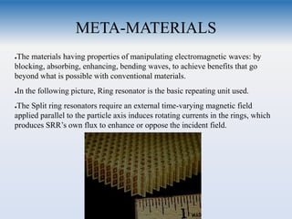
  • 1. META-MATERIALS ●The materials having properties of manipulating electromagnetic waves: by blocking, absorbing, enhancing, bending waves, to achieve benefits that go beyond what is possible with conventional materials. ●In the following picture, Ring resonator is the basic repeating unit used. ●The Split ring resonators require an external time-varying magnetic field applied parallel to the particle axis induces rotating currents in the rings, which produces SRR’s own flux to enhance or oppose the incident field.
  • 2. Split Ring Resonator ●SRR behaves as an LC resonant tank consisting of capacitance between concentric rings and overall rings inductance. ●At frequencies below the resonant frequency, the real part of magnetic permeability of SRR becomes large (positive) and goes to negative values at frequencies higher than the resonant one. ●Transmission does not occur: stop-band at opposite values of µ & ε. And vise- versa.
  • 3. INTRODUCTION to LC ●Definition: Meta-materials with simultaneously negative permittivity (ε) and permeability (µ), more commonly referred to as left-handed (LH) materials. ●The combined circuit representation is “composite right left handed” viz. CRLH ●Dual nature of the CRLH TL : At low frequencies the CRLH TL is dominantly LH, while at high frequencies the CRLH Tl is dominantly RH ●In reality, a PLH structure is not possible because of unavoidable RH parasitic series inductance (L) and shunt capacitance (C) effects.
  • 4. IMPORTANT TERMS ●The propagation constant γ = α+ jβ =√(Z*Y), ●where, α = attenuation constant; ● per-unit length impedance Z(ω) = j [ωLR− 1/ωCL] ● per-unit length admittance Y(ω) = j [ωCR− 1/ωLL] ●Phase constant β is given as: β = ω√µε, Derivation of this formula on slide 12 How is CRLH implemented?  The CRLH has either a negative permittivity (−ε) or negative permeability (−μ) in its stop-band .  By combining a −ε CRLH TL with a −μ, CRLH TL, a resonator independent of physical length similar to the Zeroth Order Resonator is obtained.
  • 5. IMPORTANT TERMS ●The characteristic impedance of a TL is given by Zo =√Z/Y. For the CRLH TL, the characteristic impedance is ●where ●The expressions of µ and ε from β and Zo;
  • 6. The β is real in pass band, as expressed in the dispersion diagrams ω vs β, below; Figure (c) illustrates the stop-band that occurs when γ is purely real, β being zero, for a CRLH TL REALIZATION OF THE GRAPH: By the relation (n=cβ/ω), at ω0, the phase shift for a TL of length d is zero (φ =−βd=0). (φ>0) occurs in the LH frequency range (ω<ω0) and (φ<0) occurs in the RH frequency range (ω>ω 0). As it will be explained later, the low- pass and high pass stop bands of RH and LH materials are obtained at upper and lower parts of the graph. Higher ω => Low pass center of RH Lower ω=> High pass center of LH This is an interpretation of equations of lossless case.
  • 7. THEORY Extracting the information from the previous figure, we observe that:  When β is purely real, a pass-band is present since γ = jβ.  β is purely imaginary since γ = α, stop-band occurs.  This stop-band is a unique characteristic of the CRLH TL, which is not present in the PRH or the PLH cases. ●Resonance and its importance:  The series and shunt resonances of the CRLH TL are different. It requires contribution from LH TL and RH TL both. This is called the unbalanced case. However, when the series and shunt resonances are equal.  LRCL =LLCR; the LH and RH contribution exactly balance each other at frequency ω0. It is important to determine the stop band frequency at which the TL transition occurs.
  • 8. THEORY ●The balanced graph: An LH to RH transition occurs at transition ●frequency ω0 ->Unbalanced =1/4* √(LRCRLCL) ● balanced =1 √LC There is a continuous transition from LH to RH for the balanced case, because γ is always purely imaginary, unlike the unbalanced case. the balanced CRLH TL’s dispersion curve does not have a stop-band.
  • 9. Continued...  The group velocity (vg = ∂ω/∂β) and phase velocity (vp = ω/β) of these TLs can be inferred from the dispersion diagram.  These diagrams show that vg and vp for a PRH TL are parallel (vgvp > 0), while vg and vp for a PLH TL are antiparallel (vgvp < 0).  In addition, the CRLH TL’s dispersion diagram shows that it has an LH (vg.vp < 0) and RH (vg.vp > 0) region.
  • 10. The 2-D CRLH TL supports wave propagation in any direction within the structure. As a result, the phase constant β is a vector quantity for the 2-D CRLH TL, −β(→) =xkx +yky where kx and ky are the propagation constants for the x and y directions. By applying PBCs to the 2-D unit cell along the x and y directions, the 2-D dispersion relation This relation reduces to as given in next slide:
  • 11. By applying periodic boundary conditions (PBCs) related to the Bloch-Floquet theorem to the LC unit cell, LC dispersion relation: Since the electrical length of the unit cell is small, the Taylor approximation cos(βp) ≈ 1 − (βp)2/2 can be applied and it becomes which is identical to the homogeneous dispersion relation of (2) (with LR= LR/p,CR= CR/p, LL=LLp,CL= CLp). Thus the LC-based CRLH TL is equivalent to the homogeneous CRLH TL for small electrical lengths.
  • 12. Difference: filter and CRLH meta-mat  CRLH structures are designed to meet specific phase responses while filters are generally designed to meet magnitude specifications.  The unit cell of CRLH metamaterials has to satisfy the homogeneity condition, |φ| < π/2, but conventional filters usually do not need to satisfy this condition.  Conventional filters are 1-D, while CRLH metamaterials can be 2- or 3-D and behave as bulk media.
  • 13. PRACTICAL IMPLEMENTATION ●An effectively homogeneous CRLH TL of length d can be constructed by cascading the band-pass LC unit cell periodically, with length as a function of phase. homogeneity condition p→0 In practice, if the unit cell is smaller than the guided wavelength p < λg/4, then the electrical length of the unit cell is smaller than π/2 and the LC- based CRLH TL is seen as effectively homogeneous.
  • 14. Choice between SMT chip and distributed components depends on the intended application. SMT chip components are difficult to implement for radiation-type applications. The RH capacitance CR is attributed to the capacitance between the trace and ground plane. The RH inductance LR is caused by the magnetic flux generated by the current flow in the digits of the interdigital capacitor.
  • 15.  The entire circuit was implemented with  Rogers RT/Duroid 5880 with dielectric constant εr = 2.2  thickness h = 1.57 mm  p = 6.1 mm, lc = 5.0 mm, wc = 2.4 mm, l s = 8.0 mm, ws = 1.0 mm  five pairs of digits with widths of 0.15 and 0.1 mm spacing.  The extracted LH and RH parameters were  LL = 3.38 nH  CL = 0.68 pF  LR = 2.45 nH  CR = 0.50 pF.  The experimental dispersion diagram is compared with the homogeneous TL relation and LC network relation
  • 16. Sievenpiper’s mushroom structure  It is, in essence, a CRLH structure capable of exhibiting a negative index of refraction.  The LH capacitance CL is provided by the capacitance couplings of the top patch with adjacent patches and the LH inductance is provided by a via connected to the ground plane.  The caps are used to enhance the weak capacitance couplings between adjacent patches. The magnetic flux by the flow of current on the top patch contributes to the RH inductance LR. The parallel-plate structure between the patch and the ground plane contributes to the RH capacitance CR. LL CR LR CL
  • 17. Dispersion diagram (first 2–3 modes) of the CRLH mushroom unit cell, obtained by full-wave-simulation (FEM) with PBCs. Dashed lines are for the open structure without the caps. The period of the unit cell is 5.0 × 5.0 mm. The two substrates used have a relative permittivity of 2.2 and thicknesses of h1 = 0.127 mm and h2 = 1.57 mm, respectively. The diameter of the vias is 0.2 mm (their length is h1 + h2 = 1.697 mm).
  • 18. Modes in mushroom structure One possible way of creating 2-D CRLH TL structures is by periodic repetition of the capacitive enhanced mushroom structure.  This dispersion diagram shows that the fundamental mode of the structure is a mixed LH–RH mode, because the LH mode of the open structure always couples with the TM air mode.  In contrast, a 2-D CRLH mushroom structure closed to air, which can be implemented by strip-line, has a dominant mode that is purely LH.  The dispersion diagram also shows that the structure has two RH modes. However, the first RH mode is actually a degenerate TE mode and does not correspond to the RH mode of the circuit model, unlike the second RH mode.  It also shows that the LH mode is shifted towards higher frequencies when the caps are removed from the mushroom structure. The removal of the caps decreases the LH CL contribution.
  • 19. Zeroth Order Resonator  a unique feature of CRLH metamaterials is that a β of zero can be achieved at a nonzero frequency.  At β = 0 there is no phase shift across the resonator since phase shift is determined by φ = −βd = 0.  The resonance is independent of the length of the structure but depends only on the reactive loadings.  quality factor is independent of the number of unit cells, given by: 𝑄 = (√CR/LL)/G where G is the shunt conductance of a lossy CRLH TL.  Note that this quality factor is independent of the number of unit cells.  The measured resonance characteristic of the ZOR is compared with Method of Moments (MoM) simulation results
  • 20. Example of zeroth order resonator: The resonator was implemented on Rogers RT/Duroid 5880 substrate with dielectric constant εr = 2.2 and thickness h = 1.57 mm.
  • 21. Zeroth Order Resonator Antenna  The antenna’s size is determined by the reactive loadings in its unit cells.  resonance is independent of physical dimensions for the ZOR, the size of the antenna can be smaller than a half-wavelength.  With a design frequency of 4.88 GHz. The size of the antenna is 10 mm, while the length of the λ/2 microstrip patch antenna with the same substrate and design frequency is 20.6 mm.
  • 22.  The antenna was implemented on a substrate with dielectric constant εr = 2.68 and thickness h = 0.79 mm. The period of the unit cell is 2.5 mm with four pairs of digits for the interdigital capacitors and three turns for the meander line.  The width of each digit and of the meander line is 100 μm. The virtual ground patch size is 2.0 × 4.8 mm2, and the antenna is matched to 50  Radiation patern for the antenna having experimental and simulated results.
  • 23. Backfire-to-Endfire Leaky-Wave Antenna A CRLH LW antenna has two distinct advantages over conventional LW antennas. 1. A CRLH LW antenna can operate at its fundamental mode, because a radiation (or fast- wave) region (|β| < k0) and a guided (or slow-wave) region (|β| > k0) coexist. (k0 is the free-space propagation constant). As shown in the graph ===> In contrast, RH structures operate at higher order modes in order to radiate and the fundamental mode of RH structures are always guided (β > k0), so they require a more complex and less- efficient feeding structure. 2. A CRLH LW antenna is capable of continuous scanning from backward (backfire) to forward (endfire) angles, unlike conventional LW antennas. This can be seen by examining the LW antenna scanning angle equation: ===> θ = sin _1[ β0 + 2nπ/p k0 ]
  • 24. where β0 is the propagation constant of the fundamental mode, n is the space harmonic, and p is the period.  For a nonperiodic LW antenna, n = 0, and β0 is the propagation constant of the operating mode.  For the CRLH LW antenna (n = 0, fundamental mode), θ can take on values from −90◦ (backfire) to +90◦ (endfire), since |β| < k0 for a continuous frequency range as seen in Figure:  By operating the CRLH LW antenna below or above its transition frequency ω0, forward and backward scanning is achieved.  Radiation is backward in Region II (LH) and forward in Region III (RH). At ω0, it radiates broadside because vg ≠ 0 at β = 0 for the balanced CRLH TL.
  • 25. Advantage of CRLH LW antenna over conventional LW antenna:  A conventional nonperiodic LW antenna cannot radiate at broadside because vg = 0 (standing wave) at β = 0 for a RH structure.  A conventional periodic LW antenna is able to scan from backfire to endfire by operating at negative and positive space harmonics (n= ±1,±2), but broadside radiation cannot occur. Operation  The scanning angle of the CRLH LW antenna discussed above is determined by its operation frequency  Continuous backfire-to-endfire scanning was achieved from 3.1 to 6.0 GHz.  To radiate efficiently, TL shown in last slide is terminated with a matched load to eliminate reflections which would otherwise produce spurious beams.
  • 26. Electronically Controlled LW Antenna In an attempt to control the nature of radiation without a compulsion of frequency control,  A frequency-independent LW antenna was produced, which is capable of continuous scanning and beamwidth control was realized with a TL composed of voltage-controlled CRLH unit cells.  By controlling the bias voltage of varactor diodes included in the CRLH unit cell, the capacitance of the cell is changed. As a result, the propagation constant of the CRLH unit cell becomes a function of voltage.  Since β is a function of V, the scanning angle becomes, θ(V) = sin _1[ β(V) k0 ]
  • 27.  For a fundamental mode => (n = 0)  The antenna functions as a voltage-controlled scanning LW antenna when voltage is uniformly distributed.  Under nonuniform voltage distribution, the propagation constant of each unit cell can be individually controlled and each cell radiates towards a different angle, giving a broader radiation beam. By controlling the voltage applied to each cell, the beam pattern of the antenna can be varied.
  • 28. Continued… Figure shows the theoretical and experimental scanning angle versus the reverse bias voltage relationship of the antenna under uniform biasing. By increasing the voltage, the antenna scans from backward to forward angles.