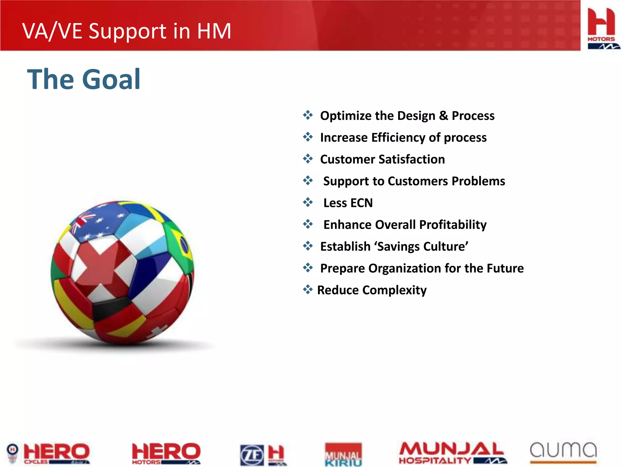
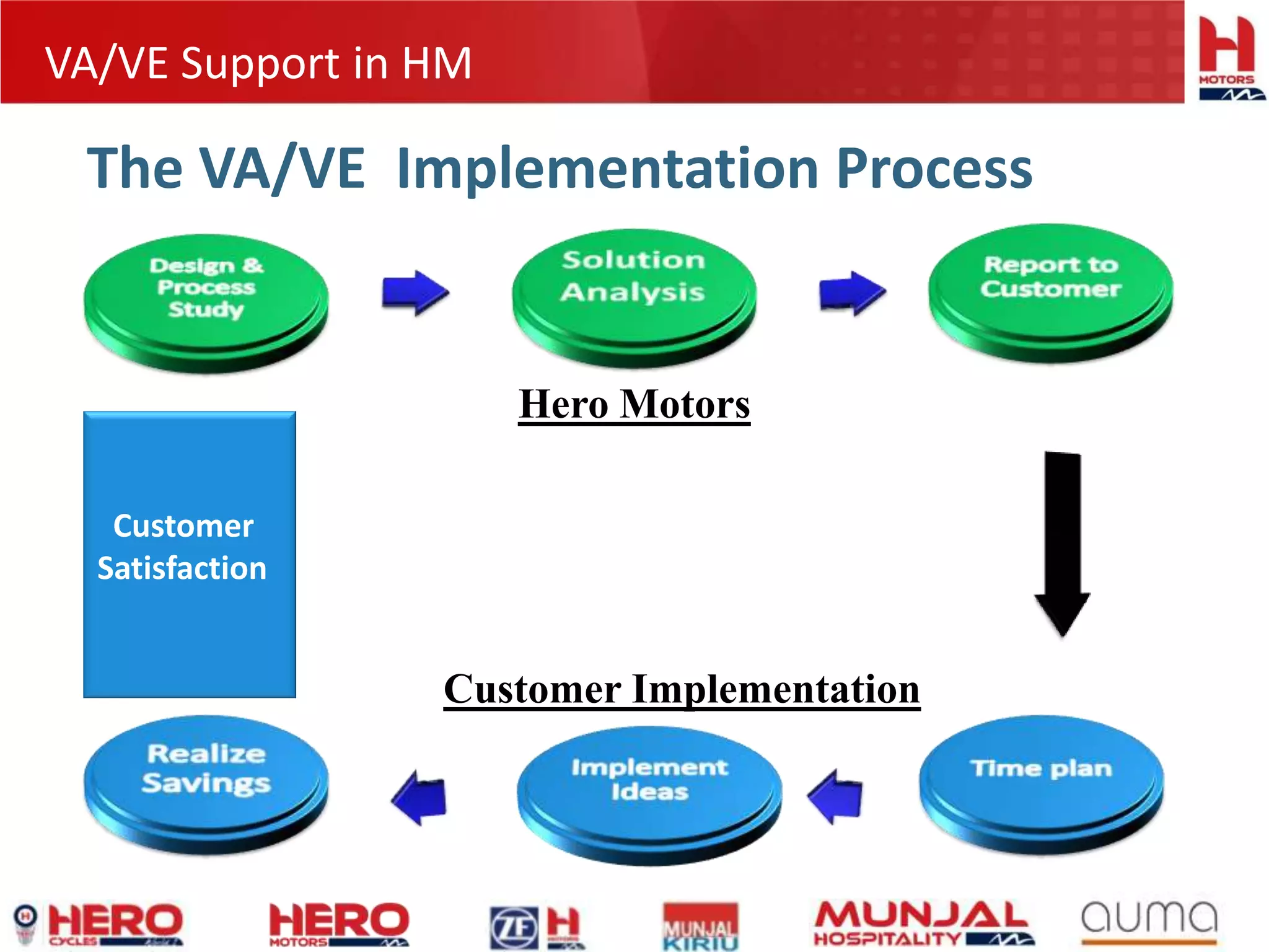
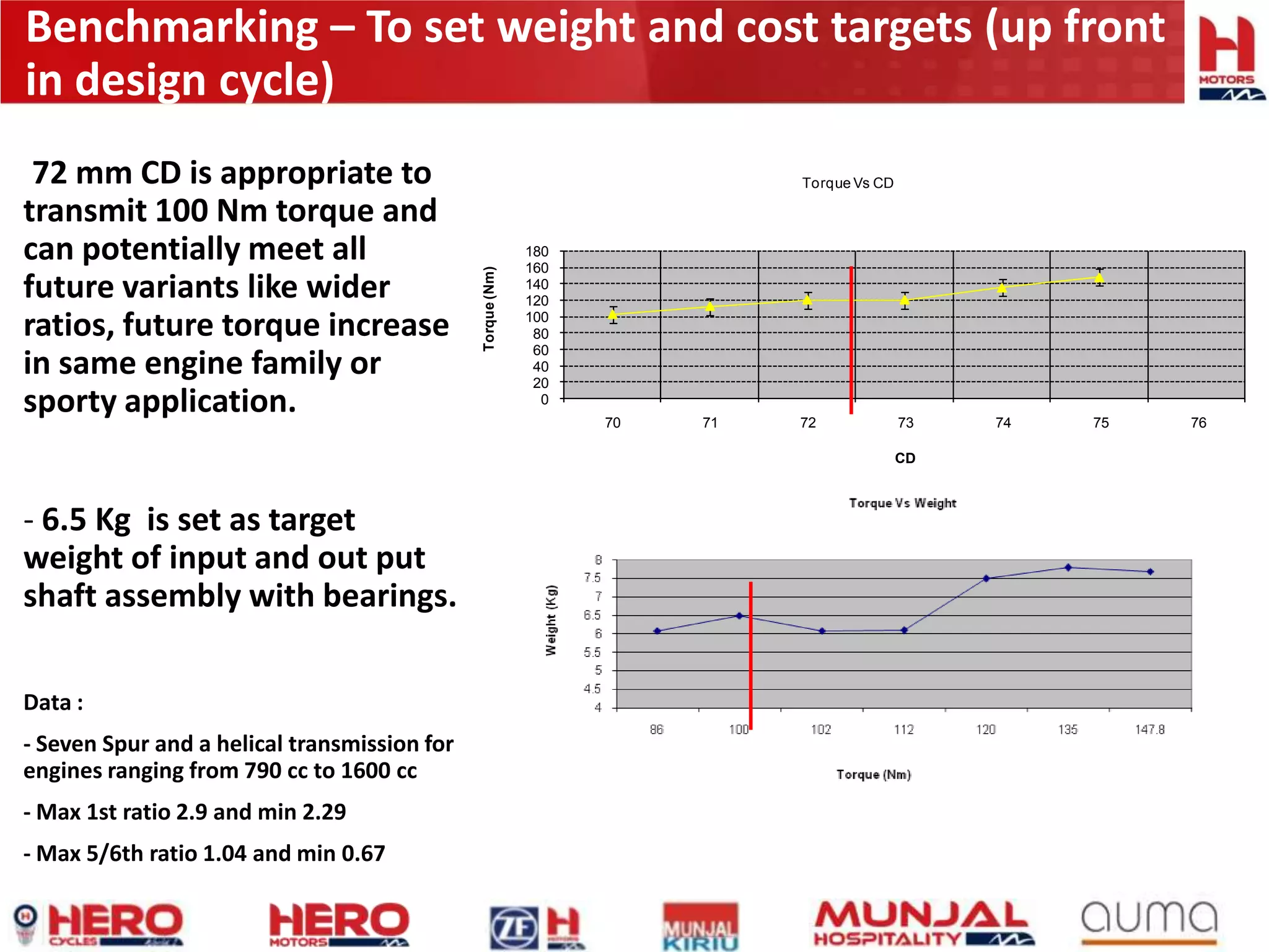
VA/VE Support By HM
Following the engineering approach
For
Cost Saving
Customer Satisfaction
VA/VE Support in HM
The Goal
 Optimize the Design & Process
 Increase Efficiency of process
 Customer Satisfaction
 Support to Customers Problems
 Less ECN
 Enhance Overall Profitability
 Establish ‘Savings Culture’
 Prepare Organization for the Future
 Reduce Complexity
VA/VE Support in HM
The VA/VE Implementation Process
Hero Motors
Customer Implementation
Customer
Satisfaction
VA/VE Support in HM
1. HML’s design and optimization process – with a case study
2. Technical Assistance Agreement with Ricardo India.
3. HML’s Manufacturing and End-Of-Line testing facilities with emphasis on
Quality Assurance.
4. HMCL’s 100 cc transmission parts under consideration and business
strategy
Highlights
VA/VE Support in HM
Design Support
PRO/e WF-3
Kissoft3-2008
Alias 12.02
Imageware-11
Icem srf4.3
Design Optimization
Design validation
Testing Facility
NVH Testing
Mechanical Testing
Reverse Engineering
Process Optimization
Highlights
Target setting -Transmission Design
Duty Cycle
System level Misalignment, TE
Transmission Spec
Safety factors and durability assessment of
Gear, Shaft & Bearings Reliability Growth test
System level Accelerated
Test
Durability test on rig
In Vehicle durability
test
Transmission Design - Flow down
Based on Transmission specifications and vehicle class, detailed targets for gear,
bearing and shaft durability, NVH and product testing specification were
developed.
Benchmarking – To set weight and cost targets (up front
in design cycle)
0
20
40
60
80
100
120
140
160
180
70 71 72 73 74 75 76
Torque(Nm)
CD
Torque Vs CD72 mm CD is appropriate to
transmit 100 Nm torque and
can potentially meet all
future variants like wider
ratios, future torque increase
in same engine family or
sporty application.
- 6.5 Kg is set as target
weight of input and out put
shaft assembly with bearings.
Data :
- Seven Spur and a helical transmission for
engines ranging from 790 cc to 1600 cc
- Max 1st ratio 2.9 and min 2.29
- Max 5/6th ratio 1.04 and min 0.67
Concept - transmission with Helical Gears
- All helical gears (except 1st) with varying helix angle to balance axial load on bearings and to make
transmission compact.
- Module ranging from 2.475 mm to 2.0 mm with CD 72 mm for 100 Nm torque engine.
- One gear is integral part of shaft in the middle to reduce gear misalignment.
- Helical gears transmit higher torque with less weight along with reduced NVH
Base line NVH before optimization
Appropriate
manufacturing
process is
selected and
micro geometry
parameters
selected based
on these results.
Hobbed gear Ground gear
Micro geometry parameters like profile crowning, slope, tip relief were chosen and optimized while
applying production variations and set of torques loads on selected parameters.
Mating Gears micro Geometry Optimization
Mating Gear transmission error and effect of load sharing
among teeth
Smooth and gradual load
transfer from one teeth to
another
Resulting smooth transmission
error. As a result, tooth
excitation force will be minimum
while transferring torque.
NVH measurement to validate
Recommended solutions
NVH Optimization - Summary
Hero motors can study system level dynamic effects on gear trains by
analyzing effects of bearing, housing, shaft on gears. This analysis guides us to
optimize micro geometry to reduce effect of gear misalignment, gear dynamic
effects and NVH. In one optimization loops, final results can be achieved.
Moreover, Hero motors also provide proto samples using KAPP grinding
machine with universal vario dresser. This will help Customer to validate micro
geometry before implementing in production and also guide customer to
foresee effects of micro geometry variations on NVH during production.
End of line testing : Transmission shaft Assembly
End of line checking: Complete gear sets, shifting all gears:
Engine Power :- 67 kw at 7250 RPM
Max Torque at Input:-250Nm
Max torque at output:-1400Nm
Gear Ratio:-
High:- 0.75
Low:-0.43
Reverse:-0.35
Bevel gear –0.40 (Apply to all gear
additionally)
Specification
1010 Gear box introduction
1010 Gear box-Component
Main Shaft Assy
Counter Shaft Assy
Shifting Drum Assy
Shift Shaft Assy
Output bevel gear
Reverse Gear
Low Speed Gear
Attachment 4 Wheel Drive
High Speed Gear
1010 Gear box-Component
Shifting Fork
810 SHO LH housing Study
Existing assy Proposed assy
Proposed cost saving
present cost Cost saving
1.Support flange removal and modification in hsg 19.84 19.84
2. 2-nos screw removal (For support flange mtg) 2.63*2 5.26
3. 2-nos dowel pin removal (For support flange) 4.88*2 9.76
4. Reduce time in Assy
5.Housing modification vendor feedback reqd.
Total cost saving Rs34.86/assy
Annual cost saving @30000 volume /yr 10.45 lac/yr
Support flange
screw
810 SHO LH Housing modification proposal
Existing Housing Proposed Housing
Removing these bosses For index lever
mtg
For shift drum assy mtg
Relieve for
intermediate
gear
For index
lever spring
stopping
1403Gear Box study
For positive locking for shaft and plate, we can lock it by making serration into both parts
Thus machining can be avoided for shaft and plate.
1403 Gear Box study
This cap can be eliminated by non machining of end of the shaft to stop coolant flowing through
the shaft
1403 Gear Train-Manufacturing problem
These all picture shows possibilities of problem in mfg when considering tolerances on root diameter
,needs to be studied by Rotax and from HERO
910435230
910435190
+ =
New designed circlip
Rotax 991 VA/VE proposals
1.Replacing these spline bushes with
split needle bearing so that Spline
machining length would be reduced
Mass removing by making ring groove to be
made in forging itself
They are using circlip and spline washer to
restrict the gears. We have propose to use new
designed circlip that will do the same function
Can be bom saving and assy time saving
proposals
1 2
P art
S .
No.
P roblem Root C aus e P ropos al D-II D-III S tatus
1 M10 Blow Hole
E xcess machining allowance
in casting
P rovide C ore hole in C asting. Yes Yes
C ore Pin added in D-II.
Implemented
2
M10 Blow Hole on
F ace of C ounter
E xcess machining allowance
in casting
P rovide C ounter in C asting. No Yes
EC R sent to Rotax.
Approval awaited.
Dowel (2) Blow Hole
Ø47.5 OD Blow Hole
Ø8.7 - LH - Blow
Hole
5
4
Yes
E xcess Machining allowance
in casting
No Yes
C hange Resting, C lamping &
Locating P ads in C asting &
Remove E xtra Material in
C asting.
E xcess Machining allowance
in casting. Throug h this
chang e we can s ave
Material, Maching C ycle
Time & R ejection of C entre
Hs g with R H Hs g
No
Yes
No
Yes
No
R H Hous ing C omponent Des ign C hanges
Outer Radius change to sharp
edge
E C R approved by
Rotax.
E C R approved by
Rotax.
7
Ø90 Blow Hole3
6
Ø8.7 - RH - Blow
Hole
F ace Blow Hole on
Gasket F ace
P rovide C ore hole in C asting.
E C R approved by
Rotax.
S olid casting change to as
cast core hole
Radius at outer profile on
face. Due to this face blow
hole problem occur & parting
line of insert is below the
radius.
EC R send to Rotax.
Approval awaited
8
E C R Approved by
Rotax.
Yes
Yes
EC R sent to Rotax.
Approval awaited
Many small chamfers & radius
on F ix S ide for which C ore
P ins are provided on both fix
and moving side due to which
casting frequently stuck on F ix
side.
E xcess Machining allowance
in casting
10
Dia 15.7&M14 C ore hole to
be made by providing the
core pin from moving side
Both side (F ix & Moving S ide)
core hole change to one side
(Moving S ide)
Yes
9
No
F requent C asting
J am in fix side
during P roduction
1
6
5
2
4
3
7
9
10
8
Process Optimization

Va.ve approach

  • 1.
    VA/VE Support ByHM Following the engineering approach For Cost Saving Customer Satisfaction
  • 2.
    VA/VE Support inHM The Goal  Optimize the Design & Process  Increase Efficiency of process  Customer Satisfaction  Support to Customers Problems  Less ECN  Enhance Overall Profitability  Establish ‘Savings Culture’  Prepare Organization for the Future  Reduce Complexity
  • 3.
    VA/VE Support inHM The VA/VE Implementation Process Hero Motors Customer Implementation Customer Satisfaction
  • 4.
    VA/VE Support inHM 1. HML’s design and optimization process – with a case study 2. Technical Assistance Agreement with Ricardo India. 3. HML’s Manufacturing and End-Of-Line testing facilities with emphasis on Quality Assurance. 4. HMCL’s 100 cc transmission parts under consideration and business strategy Highlights
  • 5.
    VA/VE Support inHM Design Support PRO/e WF-3 Kissoft3-2008 Alias 12.02 Imageware-11 Icem srf4.3 Design Optimization Design validation Testing Facility NVH Testing Mechanical Testing Reverse Engineering Process Optimization Highlights
  • 6.
  • 7.
    Duty Cycle System levelMisalignment, TE Transmission Spec Safety factors and durability assessment of Gear, Shaft & Bearings Reliability Growth test System level Accelerated Test Durability test on rig In Vehicle durability test Transmission Design - Flow down Based on Transmission specifications and vehicle class, detailed targets for gear, bearing and shaft durability, NVH and product testing specification were developed.
  • 8.
    Benchmarking – Toset weight and cost targets (up front in design cycle) 0 20 40 60 80 100 120 140 160 180 70 71 72 73 74 75 76 Torque(Nm) CD Torque Vs CD72 mm CD is appropriate to transmit 100 Nm torque and can potentially meet all future variants like wider ratios, future torque increase in same engine family or sporty application. - 6.5 Kg is set as target weight of input and out put shaft assembly with bearings. Data : - Seven Spur and a helical transmission for engines ranging from 790 cc to 1600 cc - Max 1st ratio 2.9 and min 2.29 - Max 5/6th ratio 1.04 and min 0.67
  • 9.
    Concept - transmissionwith Helical Gears - All helical gears (except 1st) with varying helix angle to balance axial load on bearings and to make transmission compact. - Module ranging from 2.475 mm to 2.0 mm with CD 72 mm for 100 Nm torque engine. - One gear is integral part of shaft in the middle to reduce gear misalignment. - Helical gears transmit higher torque with less weight along with reduced NVH
  • 10.
    Base line NVHbefore optimization Appropriate manufacturing process is selected and micro geometry parameters selected based on these results. Hobbed gear Ground gear
  • 11.
    Micro geometry parameterslike profile crowning, slope, tip relief were chosen and optimized while applying production variations and set of torques loads on selected parameters. Mating Gears micro Geometry Optimization
  • 12.
    Mating Gear transmissionerror and effect of load sharing among teeth Smooth and gradual load transfer from one teeth to another Resulting smooth transmission error. As a result, tooth excitation force will be minimum while transferring torque.
  • 13.
    NVH measurement tovalidate Recommended solutions
  • 14.
    NVH Optimization -Summary Hero motors can study system level dynamic effects on gear trains by analyzing effects of bearing, housing, shaft on gears. This analysis guides us to optimize micro geometry to reduce effect of gear misalignment, gear dynamic effects and NVH. In one optimization loops, final results can be achieved. Moreover, Hero motors also provide proto samples using KAPP grinding machine with universal vario dresser. This will help Customer to validate micro geometry before implementing in production and also guide customer to foresee effects of micro geometry variations on NVH during production.
  • 15.
    End of linetesting : Transmission shaft Assembly End of line checking: Complete gear sets, shifting all gears:
  • 16.
    Engine Power :-67 kw at 7250 RPM Max Torque at Input:-250Nm Max torque at output:-1400Nm Gear Ratio:- High:- 0.75 Low:-0.43 Reverse:-0.35 Bevel gear –0.40 (Apply to all gear additionally) Specification 1010 Gear box introduction
  • 17.
    1010 Gear box-Component MainShaft Assy Counter Shaft Assy Shifting Drum Assy Shift Shaft Assy Output bevel gear Reverse Gear Low Speed Gear Attachment 4 Wheel Drive High Speed Gear
  • 18.
  • 19.
    810 SHO LHhousing Study Existing assy Proposed assy Proposed cost saving present cost Cost saving 1.Support flange removal and modification in hsg 19.84 19.84 2. 2-nos screw removal (For support flange mtg) 2.63*2 5.26 3. 2-nos dowel pin removal (For support flange) 4.88*2 9.76 4. Reduce time in Assy 5.Housing modification vendor feedback reqd. Total cost saving Rs34.86/assy Annual cost saving @30000 volume /yr 10.45 lac/yr Support flange screw
  • 20.
    810 SHO LHHousing modification proposal Existing Housing Proposed Housing Removing these bosses For index lever mtg For shift drum assy mtg Relieve for intermediate gear For index lever spring stopping
  • 21.
    1403Gear Box study Forpositive locking for shaft and plate, we can lock it by making serration into both parts Thus machining can be avoided for shaft and plate.
  • 22.
    1403 Gear Boxstudy This cap can be eliminated by non machining of end of the shaft to stop coolant flowing through the shaft
  • 23.
    1403 Gear Train-Manufacturingproblem These all picture shows possibilities of problem in mfg when considering tolerances on root diameter ,needs to be studied by Rotax and from HERO 910435230 910435190
  • 24.
    + = New designedcirclip Rotax 991 VA/VE proposals 1.Replacing these spline bushes with split needle bearing so that Spline machining length would be reduced Mass removing by making ring groove to be made in forging itself They are using circlip and spline washer to restrict the gears. We have propose to use new designed circlip that will do the same function Can be bom saving and assy time saving proposals 1 2
  • 25.
    P art S . No. Problem Root C aus e P ropos al D-II D-III S tatus 1 M10 Blow Hole E xcess machining allowance in casting P rovide C ore hole in C asting. Yes Yes C ore Pin added in D-II. Implemented 2 M10 Blow Hole on F ace of C ounter E xcess machining allowance in casting P rovide C ounter in C asting. No Yes EC R sent to Rotax. Approval awaited. Dowel (2) Blow Hole Ø47.5 OD Blow Hole Ø8.7 - LH - Blow Hole 5 4 Yes E xcess Machining allowance in casting No Yes C hange Resting, C lamping & Locating P ads in C asting & Remove E xtra Material in C asting. E xcess Machining allowance in casting. Throug h this chang e we can s ave Material, Maching C ycle Time & R ejection of C entre Hs g with R H Hs g No Yes No Yes No R H Hous ing C omponent Des ign C hanges Outer Radius change to sharp edge E C R approved by Rotax. E C R approved by Rotax. 7 Ø90 Blow Hole3 6 Ø8.7 - RH - Blow Hole F ace Blow Hole on Gasket F ace P rovide C ore hole in C asting. E C R approved by Rotax. S olid casting change to as cast core hole Radius at outer profile on face. Due to this face blow hole problem occur & parting line of insert is below the radius. EC R send to Rotax. Approval awaited 8 E C R Approved by Rotax. Yes Yes EC R sent to Rotax. Approval awaited Many small chamfers & radius on F ix S ide for which C ore P ins are provided on both fix and moving side due to which casting frequently stuck on F ix side. E xcess Machining allowance in casting 10 Dia 15.7&M14 C ore hole to be made by providing the core pin from moving side Both side (F ix & Moving S ide) core hole change to one side (Moving S ide) Yes 9 No F requent C asting J am in fix side during P roduction 1 6 5 2 4 3 7 9 10 8 Process Optimization