
Recommended
Recommended
More Related Content
Similar to Yale b875 glp050 vx lift truck service repair manual
Similar to Yale b875 glp050 vx lift truck service repair manual (9)
More from fjskefksemer
More from fjskefksemer (20)
Recently uploaded
Recently uploaded (20)
Yale b875 glp050 vx lift truck service repair manual
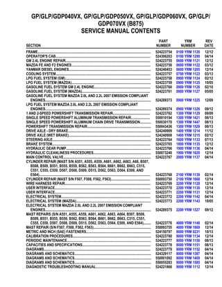
- 1. GP/GLP/GDP040VX, GP/GLP/GDP050VX, GP/GLP/GDP060VX, GP/GLP/ GDP070VX (B875) SERVICE MANUAL CONTENTS SECTION PART NUMBER YRM NUMBER REV DATE FRAME............................................................................................................................ 524223754 0100 YRM 1120 12/12 OPERATOR'S CAB........................................................................................................ 524306203 0100 YRM 1290 04/14 GM 2.4L ENGINE REPAIR............................................................................................. 524223755 0600 YRM 1121 12/12 MAZDA FE AND F2 ENGINES....................................................................................... 524223756 0600 YRM 1122 03/12 YANMAR DIESEL ENGINES.......................................................................................... 524240453 0600 YRM 1205 12/14 COOLING SYSTEM........................................................................................................ 524223757 0700 YRM 1123 03/13 LPG FUEL SYSTEM (GM).............................................................................................. 524223758 0900 YRM 1124 02/12 LPG FUEL SYSTEM (MAZDA)....................................................................................... 524223759 0900 YRM 1125 10/05 GASOLINE FUEL SYSTEM GM 2.4L ENGINE.............................................................. 524223760 0900 YRM 1126 02/10 GASOLINE FUEL SYSTEM (MAZDA)........................................................................... 524223761 0900 YRM 1127 05/05 GASOLINE FUEL SYSTEM MAZDA 2.0L AND 2.2L 2007 EMISSION COMPLIANT ENGINES.................................................................................................................... 524289373 0900 YRM 1325 12/09 LPG FUEL SYSTEM MAZDA 2.0L AND 2.2L 2007 EMISSION COMPLIANT ENGINES.................................................................................................................... 524289374 0900 YRM 1326 09/12 1 AND 2-SPEED POWERSHIFT TRANSMISSION REPAIR......................................... 524223762 1300 YRM 1129 09/09 SINGLE SPEED POWERSHIFT ALUMINUM TRANSMISSION REPAIR..................... 550010194 1300 YRM 1421 08/13 SINGLE SPEED POWERSHIFT ALUMINUM CHAIN DRIVE TRANSMISSION............ 550030170 1300 YRM 1447 08/13 POWERSHIFT TRANSMISSION REPAIR...................................................................... 550043436 1300 YRM 1529 08/13 DRIVE AXLE - DRY BRAKE........................................................................................... 524240909 1400 YRM 1214 11/12 DRIVE AXLE (WET BRAKE).......................................................................................... 524240908 1400 YRM 1215 02/12 STEERING AXLE............................................................................................................ 524223764 1600 YRM 1133 07/13 BRAKE SYSTEM............................................................................................................ 524223765 1800 YRM 1135 12/12 HYDRAULIC GEAR PUMP............................................................................................. 524223766 1900 YRM 1136 04/14 HYDRAULIC CLEANLINESS PROCEDURES............................................................... 550073240 1900 YRM 1620 12/14 MAIN CONTROL VALVE................................................................................................ 524223767 2000 YRM 1137 04/14 CYLINDER REPAIR (MAST S/N A551, A555, A559, A661, A662, A663, A66, B507, B508, B509, B551, B555, B559, B562, B563, B564, B661, B662, B663, C515, C551, C555, C559, D507, D508, D509, D515, D562, D563, D564, E509, AND E564).......................................................................................................................... 524223768 2100 YRM 1139 02/14 CYLINDER REPAIR (MAST S/N F507, F508, F562, F563)........................................... 550093750 2100 YRM 1668 12/14 WIRE HARNESS REPAIR.............................................................................................. 524223769 2200 YRM 1128 12/14 USER INTERFACE......................................................................................................... 524223770 2200 YRM 1130 12/14 USER INTERFACE......................................................................................................... 524223771 2200 YRM 1131 12/14 ELECTRICAL SYSTEM.................................................................................................. 524223772 2200 YRM 1142 04/14 ELECTRICAL SYSTEM (MAZDA).................................................................................. 524223773 2200 YRM 1143 10/05 ELECTRICAL SYSTEM MAZDA 2.0L AND 2.2L 2007 EMISSION COMPLIANT ENGINES.................................................................................................................... 524289375 2200 YRM 1327 09/12 MAST REPAIRS (S/N A551, A555, A559, A661, A662, A663, A664, B507, B508, B509, B551, B555, B559, B562, B563, B564, B661, B662, B663, C515, C551, C555, C559, D507, D508, D509, D515, D562, D563, D564, E509, AND E564)........ 524223776 4000 YRM 1148 02/14 MAST REPAIR (S/N F507, F508, F562, F563)............................................................... 550093755 4000 YRM 1669 12/14 METRIC AND INCH (SAE) FASTENERS....................................................................... 524150797 8000 YRM 0231 10/13 CALIBRATION PROCEDURES...................................................................................... 524223780 8000 YRM 1134 12/14 PERIODIC MAINTENANCE............................................................................................ 524223777 8000 YRM 1150 08/13 CAPACITIES AND SPECIFICATIONS........................................................................... 524223778 8000 YRM 1151 08/13 DIAGRAMS..................................................................................................................... 524223779 8000 YRM 1152 04/14 DIAGRAMS AND SCHEMATICS.................................................................................... 524329117 8000 YRM 1387 04/14 DIAGRAMS AND SCHEMATICS.................................................................................... 550001092 8000 YRM 1409 04/14 DIAGRAMS AND SCHEMATICS.................................................................................... 550055283 8000 YRM 1585 04/14 DIAGNOSTIC TROUBLESHOOTING MANUAL............................................................ 524221866 9000 YRM 1112 12/14
- 2. 100 YRM 1120 Description General WARNING The lift truck must be put on blocks for some types of maintenance and repairs. The removal of the following assemblies will cause large changes in the center of gravity: mast, drive axle, engine and transmission, and counterweight. When the lift truck is put on blocks, put additional blocks in the following positions to maintain stability: • Before removing the mast and drive axle, put blocks under the counterweight so the lift truck cannot fall backward. • Before removing the counterweight, put blocks under the mast assembly so the lift truck cannot fall forward. The surface must be solid, even, and level when the lift truck is put on blocks. Make sure that any blocks used to support the lift truck are solid, one-piece units. See the Operating Manual or the section Periodic Maintenance 8000 YRM 1150 for lift truck models • GLC20-35VX (GC/GLC040-070VX, GC/GLC055SVX) (A910) • GLP/GDP20-35VX (GP/GLP/GDP040-070VX) (B875) Periodic Maintenance 8000 YRM 1207 for lift truck models • GC/GLC030VX, GC/GLC035VX, GC/GLC040SVX (C809) • GLP/GDP16VX, GLP/GDP18VX, GLP/GDP20SVX (GP/GLP/GDP030VX, GP/GLP/GDP035VX, GP/GLP/GDP040SVX) (C810) NOTE: For exhaust system procedure for lift trucks equipped with a Mazda 2007 emissions compliant engine and for lift trucks built after January, 2010 go to section LPG Fuel System, Mazda FE and F2 Emis- sion Compliant Engines 900 YRM 1326 or Gasoline Fuel System, Mazda FE and F2Emission Compliant Engines 900 YRM 1325 for exhaust system proce- dures. For lift trucks built after January, 2010 and equipped with a GM 2.4L engine, go to section LPG Fuel System, GM 2.4L Engine 900 YRM 1124 for exhaust system procedures. This section contains the description of the frame (see Figure 1) and connected parts. Procedures for remov- ing and installing the counterweight, hood, overhead guard, engine, cooling system, and exhaust system (see NOTE above) are found in this section. Checks for the operator restraint system and procedures for the repair of tanks and installation of safety labels are also included. Description The frame is one weldment and includes the hydraulic tank and fuel tank for gasoline or diesel fuel. See Fig- ure 1. There is a counterweight for each capacity of lift truck. The counterweights are similar in appearance, but are different weights. See Table 3 for lift truck models • GLC20-35VX (GC/GLC040-070VX, GC/GLC055SVX) (A910) Table 4 for lift truck models • GC/GLC030VX, GC/GLC035VX, GC/GLC040SVX (C809) Table 5 for lift truck models • GLP/GDP16VX, GLP/GDP18VX, GLP/GDP20SVX (GP/GLP/GDP030VX, GP/GLP/GDP035VX, GP/GLP/GDP040SVX) (C810) Table 6 for lift truck models • GLP/GDP20-35VX (GP/GLP/GDP040-070VX) (B875) The muffler is fastened to the frame inside the counter- weight. The overhead guard, cowl, and hood are installed on the frame. The hood is connected to the frame with hinges. Two gas-controlled springs provide assistance when raising the hood and hold the hood in the open po- sition. The floor plate and side covers can be removed for access to the engine, transmission, and other com- ponents. 1
- 3. Hood, Seat, and Side Covers Replacement 100 YRM 1120 1. COWL PLATE 2. FENDERS 3. FRAME 4. HOOD MOUNTS 5. COUNTERWEIGHT MOUNTS 6. FUEL TANK (GAS OR DIESEL) 7. HYDRAULIC TANK Figure 1. Frame Hood, Seat, and Side Covers Replacement REMOVE 1. Slide seat to the closest position to steering column. 2. Fully tilt steering column forward. 3. If your truck is equipped with an LPG tank, swing tank off to the side. 4. Raise latch on the left, front corner of the hood to unlatch and lift up hood. See Figure 2. 5. Remove floor mat and floor plate. See Figure 3 for lift truck models • GLC20-35VX (GC/GLC040-070VX, GC/GLC055SVX) (A910) • GLP/GDP16VX, GLP/GDP18VX, GLP/GDP20SVX (GP/GLP/GDP030VX, GP/GLP/GDP035VX, GP/GLP/GDP040SVX) (C810) • GC/GLC030VX, GC/GLC035VX, GC/GLC040SVX (C809) See Figure 4 for lift truck models • GLP/GDP20-35VX (GP/GLP/GDP040-070VX) (B875) 2
- 4. 100 YRM 1120 Hood, Seat, and Side Covers Replacement NOTE: SWIVEL SEAT AND VENTED HOOD ARE OPTIONAL FEATURES. A. SIDE VIEW OF HOOD AND SEAT B. SIDE VIEW OF HOOD C. BOTTOM VIEW OF HOOD D. SIDE VIEW OF VENTED HOOD WITH SWIVEL SEAT 1. SEAT 2. HOOD 3. FRAME 4. SEAT WIRE HARNESS 5. SEAT WIRE HARNESS CONNECTOR (WITHOUT ELECTRONIC CONTROL) 6. SEAT WIRE HARNESS CONNECTOR (WITH ELECTRONIC CONTROL) 7. CABLE CLIPS 8. HINGE SCREWS 9. GAS SPRING 10. ATTACHMENT HOLES ATTACHING HOOD TO SEAT (SEMI-SUSPENSION) 11. SEAT WIRE HARNESS BRACKETS 12. SEAT LINER 13. HOOD LATCH 14. ATTACHMENT HOLES ATTACHING HOOD TO SEAT (NON-SUSPENSION) 15. ATTACHMENT HOLES ATTACHING HOOD TO SEAT (FULL SUSPENSION) 16. SPACER Figure 2. Hood and Seat Arrangement 3
- 5. Hood, Seat, and Side Covers Replacement 100 YRM 1120 1. LOWER STEERING COLUMN COVER 2. UPPER STEERING COLUMN COVER 3. INSERT 4. CLIP 5. DASHBOARD 6. CAPSCREW 7. SEAL 8. GROMMET 9. LEFT HAND REAR PANEL 10. FLOOR PLATE 11. LEFT HAND FENDER COVER 12. SCREW 13. NUT 14. LEFT HAND FRONT PANEL 15. LEFT HAND STEP PANEL 16. LEFT HAND TREAD PLATE 17. PLATE ASSEMBLY SEAL 18. RIGHT HAND FENDER COVER 19. FLOOR MAT 20. RIGHT HAND TREAD PLATE 21. RIGHT HAND FRONT PANEL 22. RIGHT HAND STEP PANEL 23. RIGHT HAND REAR PANEL 24. RADIATOR COVER 25. KICK PANEL 26. PLATE ASSEMBLY Figure 3. Side Cover, Floor Plate, and Cowl Components, Lift Truck Models GLC20-35VX (GC/GLC040-070VX,GC/GLC055SVX ) (A910), GLP/GDP16-18VX, GLP/GDP20SVX (GP/GLP/GDP030-35VX, GP/GLP/GDP040SVX ) (C810), and GC/GLC030-035VX, GC/GLC040SVX (C809) 4
- 6. 100 YRM 1120 Hood, Seat, and Side Covers Replacement 6. Remove two capscrews holding left and right rear side covers to the frame. Remove rear side covers from frame. See Figure 3 for lift truck models • GLC20-35VX (GC/GLC040-070VX, GC/GLC055SVX) (A910) • GLP/GDP16VX, GLP/GDP18VX, GLP/GDP20SVX (GP/GLP/GDP030VX, GP/GLP/GDP035VX, GP/GLP/GDP040SVX) (C810) • GC/GLC030VX, GC/GLC035VX, GC/GLC040SVX (C809) See Figure 4 for lift truck models • GLP/GDP20-35VX (GP/GLP/GDP040-070VX) (B875) 7. Remove two capscrews holding left and right fender covers to front overhead guard leg. Remove cov- ers. See Figure 3 for lift truck models • GLC20-35VX (GC/GLC040-070VX, GC/GLC055SVX) (A910) • GLP/GDP16VX, GLP/GDP18VX, GLP/GDP20SVX (GP/GLP/GDP030VX, GP/GLP/GDP035VX, GP/GLP/GDP040SVX) (C810) • GC/GLC030VX, GC/GLC035VX, GC/GLC040SVX (C809) See Figure 4 for lift truck models • GLP/GDP20-35VX (GP/GLP/GDP040-070VX) (B875) 8. Remove four capscrews holding left and right front side covers to frame. Remove covers. 9. Fully lower steering column. 10. Remove upper steering column cover by pulling up on upper steering column cover to release latches (one on either side), and pulling cover away from steering column. See Figure 5. 11. Remove five fasteners (see Figure 5) securing dash to the top of cowl. Remove four clips, located un- derneath dash, that attach dash to the kick panel. Lift to remove dash. 12. Lift the kick panel to remove from truck. See Figure 3 for lift truck models • GLC20-35VX (GC/GLC040-070VX, GC/GLC055SVX) (A910) • GLP/GDP16VX, GLP/GDP18VX, GLP/GDP20SVX (GP/GLP/GDP030VX, GP/GLP/GDP035VX, GP/GLP/GDP040SVX) (C810) • GC/GLC030VX, GC/GLC035VX, GC/GLC040SVX (C809) See Figure 4 for lift truck models • GLP/GDP20-35VX (GP/GLP/GDP040-070VX) (B875) 13. Remove three capscrews holding the seal plate. Remove seal plate. See Figure 6. 14. Disconnect seat wire harness connector. See Fig- ure 2. CAUTION When removing the seat from the hood, DO NOT use an impact wrench to remove the capscrews. Dam- age can be caused to the threads on the screws and in the holes. 15. If seat is to be removed, and truck is equipped with a non-swivel seat, remove seat wire harness from seat wire harness brackets that are attached to the underside of hood. Remove the cable clips from the seat wire harness. If truck is equipped with a swivel seat, remove seat wire harness from seat wire harness bracket attached to underside of the hood and behind the seat (see Figure 2). 16. Remove four capscrews and washers holding the seat to hood. Lift seat off the hood. Pull seat wire harness through hood. See Figure 2. 17. Remove capscrews and washers at the top of gas springs. Remove gas springs from hood. 18. Remove hinge screws, located in the rear of the hood. 19. Lift hood from the truck. See Figure 2. 5
- 7. Hood, Seat, and Side Covers Replacement 100 YRM 1120 Figure 4. Side Covers, Floor Plate, and Cowl Components, Lift Truck Models GLP/GDP20-35VX (GP/GLP/GDP040-070VX) (B875) 6
- 8. 100 YRM 1120 Hood, Seat, and Side Covers Replacement Legend for Figure 4 1. DASH ASSEMBLY 2. UPPER STEERING COLUMN COVER 3. LOWER STEERING COLUMN COVER 4. KICK PANEL 5. MUD GUARD (LH) 6. MUD GUARD (RH) 7. LOCK NUT 8. NUT 9. COVER 10. BRACKET 11. PLATE ASSEMBLY 12. GROMMET 13. LEFT FRONT PANEL 14. RIGHT FRONT PANEL 15. LEFT STEP PANEL 16. RIGHT STEP PANEL 17. LEFT STEP PLATE 18. RIGHT STEP PLATE 19. LEFT REAR PANEL 20. RIGHT REAR PANEL 21. FLOOR MAT 22. FLOOR PLATE 23. RADIATOR COVER 24. SEALS 25. CAPSCREW 26. CLIP NUT 27. INSERT 28. PLATE ASSEMBLY SEAL NOTE: TOP VIEW OF DASH SHOWN. A. INDICATES TO PULL UP TO UNLATCH 1. ALLEN SCREWS 2. COWL 3. UPPER STEERING COLUMN COVER 4. LOWER STEERING COLUMN COVER Figure 5. Remove Dash From Cowl 7
- 9. Hood, Seat, and Side Covers Replacement 100 YRM 1120 INSTALL 1. Place hood onto the lift truck frame. 2. Install hinge screws, located in the rear of the hood, and tighten to 38 N•m (28 lbf ft). See Figure 2. 3. Align top holes in the gas springs with holes in hood. Install capscrews and washers to attach gas springs to hood. Tighten capscrews to 19.2 N•m (170 lbf in). See Figure 7 and Table 1 for lift truck models • GLP/GDP16VX, GLP/GDP18VX, GLP/GDP20SVX (GP/GLP/GDP030VX, GP/GLP/GDP035VX, GP/GLP/GDP030SVX) (C810) and GLC20-35VX (GC/GLC040-070VX, GC/GLC055SVX) (A910) See Figure 8 for lift truck models • GC/GLC030VX, GC/GLC035VX, GC/GLC040SVX (C809) See Figure 9 and Table 2 for lift truck models • GLP/GDP20-35VX (GP/GLP/GDP040-070VX) (B875) 1. CAPSCREWS 2. SEAL PLATE Figure 6. Remove Seal Plate From Dash 8
- 10. 100 YRM 1120 Hood, Seat, and Side Covers Replacement Figure 7. Gas Spring Installation, Lift Truck Models GLP/GDP16VX, GLP/GDP18VX, GLP/GDP20SVX (GP/GLP/GDP030VX, GP/GLP/GDP035VX, GP/GLP/GDP030SVX) (C810) and GLC20-35VX (GC/GLC040-070VX, GC/GLC055SVX) (A910) Legend for Figure 7 NOTE: LEFT SIDE SHOWN A. MOUNTING LOCATION FOR CYLINDER END OF GAS SPRING FOR NON-SUSPENSION SEAT B. MOUNTING LOCATION FOR CYLINDER END OF GAS SPRING FOR SEMI OR FULL SUSPENSION SEAT C. MOUNTING LOCATION FOR CYLINDER END OF GAS SPRING FOR SEMI OR FULL SUSPENSION SEAT WITH CAB* 1. MOUNTING POINTS FOR GAS SPRING ON HOOD *CAB ONLY ON LIFT TRUCK MODELS GLP/ GDP16VX, GLP/GDP18VX, GLP/GDP20SVX (GP/ GLP/GDP030VX, GP/GLP/GDP035VX, GP/GLP/ GDP030SVX) (C810) Table 1. Gas Spring Installation, Lift Truck Models GLP/GDP16VX, GLP/GDP18VX, GLP/GDP20SVX (GP/GLP/GDP030VX, GP/GLP/GDP035VX, GP/GLP/GDP030SVX) (C810) and GLC20-35VX (GC/GLC040-070VX, GC/GLC055SVX) (A910) Full or Semi Suspension Seat Non-Suspension Seat Frame Hood Frame Hood Left Side Right Side Left Side Right Side Left Side Right Side Left Side Right Side Seat Without E-Control B B 3 3 A A 1 1 Seat With E-Control B B 2 2 N/A N/A N/A N/A Cab C C 2 2 N/A N/A N/A N/A 9
- 11. Hood, Seat, and Side Covers Replacement 100 YRM 1120 Figure 8. Gas Spring Installation, Lift Truck Models GC/GLC030VX, GC/GLC035VX, GC/GLC040SVX (C809) Legend for Figure 8 NOTE: LEFT SIDE SHOWN. 1. MOUNTING LOCATION FOR CYLINDER END OF GAS SPRING FOR NON-SUSPENSION SEAT 2. MOUNTING LOCATION FOR CYLINDER END OF GAS SPRING FOR SEMI OR FULL SUSPENSION SEAT Figure 9. Gas Spring Installation, Lift Truck Models GLP/GDP20-35VX (GP/GLP/GDP040-070VX) (B875) 10
- 12. 100 YRM 1120 Hood, Seat, and Side Covers Replacement Legend for Figure 9 A. LEFT SIDE B. RIGHT SIDE C. MOUNTING LOCATION FOR CYLINDER END OF GAS SPRING FOR NON-SUSPENSION SEAT D. MOUNTING LOCATION FOR CYLINDER END OF GAS SPRING FOR SEMI OR FULL SUSPENSION SEAT, LIFT TRUCKS WITH CAB OR GP/GLP/GDP040-070VX (B875) LIFT TRUCKS WITHOUT CAB E. MOUNTING LOCATION FOR CYLINDER END OF GAS SPRING FOR SEMI OR FULL SUSPENSION SEAT, LIFT TRUCKS GLP/GDP20-35VX (B875) WITHOUT CAB 1. MOUNTING POINTS FOR GAS SPRING ON HOOD Table 2. Gas Spring Installation, Lift Truck Models GLP/GDP20-35VX (GP/GLP/GDP040-070VX) (B875) Full or Semi Suspension Seat Non-Suspension Seat Frame Hood Frame Hood Left Side Right Side Left Side Right Side Left Side Right Side Left Side Right Side Non-Cab GP/GLP/ GDP040- 070VX (B875) D D 3 3 C C 1 1 Non-Cab GLP/ GDP20- 35VX (B875) E E 2 2 C C 1 1 Cab D D 1 1 N/A N/A N/A N/A 11
- 13. Hood, Seat, and Side Covers Replacement 100 YRM 1120 4. Install latch striker in highest slot position. Check that latch striker is in center of jaws of hood latch when hood closes. Open and close hood to ensure that center pin strikes hood latch properly and that the stop screw contacts frame. A properly closed hood MUST click twice on the hood latch. If the hood latch does not close properly, loosen cap- screws on the back of center pin and adjust center pin up or down as required for correct alignment. See Figure 10. 5. Push down until hood just touches rubber bumper. Make sure latch striker is still in center of hood latch. Open hood and tighten capscrews for latch. 6. Check operation of hood latch. Have an operator sit in seat. Make sure hood is fully closed (two clicks). Also check that hood touches rubber bumper. If necessary, repeat Step 5. 1. HOOD 2. HOOD LATCH 3. CENTER PIN 4. CAPSCREW Figure 10. Hood Latch Adjustment CAUTION When installing the seat to the hood, DO NOT use an impact wrench to install the capscrews. Damage can be caused to the threads on the screws and in the holes. 7. Place seat on the hood and thread seat wire har- ness through the hole in the hood. See Figure 2. 8. Align holes in the seat with the holes in hood. In- sert washers and capscrews. Tighten capscrews to 18 N•m (159 lbf in). 9. If truck is equipped with a non-swivel seat, tie cable clips to seat wire harness and insert harness into seat wire harness brackets under hood. If truck is equipped with a swivel seat, secure seat harness to bracket. See Figure 2. 10. Install seal plate using three capscrews. See Fig- ure 6. 11. Install kick panel onto truck. See Figure 3 for lift truck models • GLC20-35VX (GC/GLC040-070VX, GC/GLC055SVX) (A910) • GLP/GDP16VX, GLP/GDP18VX, GLP/GDP20SVX (GP/GLP/GDP030VX, GP/GLP/GDP035VX, GP/GLP/GDP040SVX) (C810) • GC/GLC030VX, GC/GLC035VX, GC/GLC040SVX (C809) See Figure 4 for lift truck models • GLP/GDP20-35VX (GP/GLP/GDP040-070VX) (B875) 12. Install dash to top of cowl. See Figure 5. Install four clips to attach the dash to kick panel. 13. Install upper steering column cover to dash. 14. Using four capscrews, install left and right front side covers to frame. See Figure 3 for lift truck models • GLC20-35VX (GC/GLC040-070VX, GC/GLC055SVX) (A910) • GLP/GDP16VX, GLP/GDP18VX, GLP/GDP20SVX (GP/GLP/GDP030VX, GP/GLP/GDP035VX, GP/GLP/GDP040SVX) (C810) • GC/GLC030VX, GC/GLC035VX, GC/GLC040SVX (C809) 12
- 14. Thank you very much for your reading. Please Click Here. Then Get COMPLETE MANUAL. NO WAITING NOTE: If there is no response to click on the link above, please download the PDF document first and then click on it.
- 15. 100 YRM 1120 Steering Column See Figure 4 for lift truck models • GLP/GDP20-35VX (GP/GLP/GDP040-070VX) (B875) 15. Using two capscrews, install left and right fender covers to front of overhead guard legs. 16. Using two capscrews, install left and right rear side covers to frame. See Figure 3 for lift truck models • GLC20-35VX (GC/GLC040-070VX, GC/GLC055SVX) (A910) • GLP/GDP16VX, GLP/GDP18VX, GLP/GDP20SVX (GP/GLP/GDP030VX, GP/GLP/GDP035VX, GP/GLP/GDP040SVX) (C810) • GC/GLC030VX, GC/GLC035VX, GC/GLC040SVX (C809) See Figure 4 for lift truck models • GLP/GDP20-35VX (GP/GLP/GDP040-070VX) (B875) 17. Install floor mat and floor plate. 18. If truck is equipped with an LPG tank, swing LPG tank into position on back of counterweight. 19. Adjust the steering column and seat positions. Steering Column DESCRIPTION This section describes the repair procedures for the steering column. The steering column assembly mounts to the cowl inside the operator compartment and is the mechanical connection between the steering wheel and the steering control unit. The steering col- umn includes the steering wheel, housing, bracket and lower shaft. For lift trucks with gas and LPG engines, bolts and bushings attach the steering column to the cowl standoffs. For lift trucks with diesel engines, bolts, bushings and isolators attach the steering column to the cowl standoffs. See Figure 11. STEERING COLUMN REPAIR Remove 1. Put blocks on each side (front and back) of tires to prevent lift truck from moving. WARNING Disconnect the battery before removing any covers to avoid injury to personnel. 2. Attach a tag on the battery connector or nega- tive battery cable stating, DO NOT CONNECT BATTERY. Move the steering column to the most FORWARD position. CAUTION If a puller tool is used to remove steering wheel from steering column, be careful not to damage horn wires. NOTE: This procedure is for the removal of all compo- nents of the steering column assembly. Not all com- ponents are removed for a repair procedure. Do only those steps of the procedure necessary to remove the required component. NOTE: Tag wires prior to disconnect. 3. Remove the horn button assembly and disconnect electrical wires. Remove large hex nut and steering wheel from steering column. See Figure 12. NOTE: DIESEL SHOWN, LPG AND GAS SIMILAR. 1. STEERING WHEEL 2. STEERING COLUMN 3. COWL Figure 11. Steering Column and Cowl 13
- 16. Steering Column 100 YRM 1120 1. HORN BUTTON 2. HEX NUT 3. STEERING WHEEL 4. STEERING COLUMN Figure 12. Steering Wheel Remove/Install 4. Remove steering column covers. Remove floor mats and floor plate. See section Hood, Seat, and Side Covers Replacement. NOTE: Perform Step 5 for lift trucks equipped with gas or LPG engines. 5. Remove four capscrews, four bushings and steer- ing column from cowl standoffs. See Figure 13. NOTE: Perform Step 6 for lift trucks equipped with diesel engines. 6. Remove four capscrews, four bushings, four isola- tors, steering column and four isolators from cowl standoffs. See Figure 13. NOTE: DIESEL SHOWN, LPG AND GAS SIMILAR. 1. CAPSCREW 2. BUSHING 3. ISOLATOR 4. STEERING COLUMN 5. COWL STANDOFF Figure 13. Steering Column Remove/Install 14
- 17. 100 YRM 1120 Steering Column Disassemble NOTE: Remove and discard snap rings if installed. 1. Remove two pins and gas spring from housing. See Figure 14, for lift trucks manufactured before January, 2012. See Figure 15, for lift trucks manufactured after Jan- uary, 2012. 2. Remove two pivot bolts, two bushings, two nuts and bracket from housing. See Figure 14, for lift trucks manufactured before January, 2012. See Figure 15, for lift trucks manufactured after Jan- uary, 2012. 3. Remove split pin and lower shaft from upper shaft. See Figure 14, for lift trucks manufactured before January, 2012. See Figure 15, for lift trucks manufactured after Jan- uary, 2012. 4. Remove connector from connector bracket. Re- move connector bracket, fastener, four screws and two horn contacts from housing. See Figure 14, for lift trucks manufactured before January, 2012. See Figure 15, for lift trucks manufactured after Jan- uary, 2012. Clean WARNING Cleaning solvents can be flammable and toxic and can cause skin irritation. When using cleaning solvents, always follow the solvent manufacturer’s recommended safety precautions. WARNING Compressed air is used for cleaning and drying pur- poses, or for cleaning restrictions. Wear protective clothing (goggles/shields, gloves, etc.). Make sure the path of the compressed air is away from all per- sonnel to avoid injury. 1. Clean metal parts in solvent. Remove all traces of old lubricant and dirt. Clean nonmetal parts with warm soapy water and a lint free cloth. 2. After cleaning, dry parts with compressed air. DO NOT dry parts with a cloth. Inspect 1. Inspect for loose, burned, missing, cracked or dam- aged hardware. 2. Inspect all parts for dents, holes, bends, burrs, rust, corrosion or marred finishes. 3. Replace all defective or damaged parts. Assemble NOTE: This procedure is for the installation of all com- ponents of the steering column assembly. Not all com- ponents are removed for a repair procedure. Do only those steps of the procedure necessary to install the required component. NOTE: Perform Step 1 only for lift trucks manufactured before January, 2012. 1. Lubricate the horn contact slip rings with a small amount of conductive grease (Yale P/N 582014302). 2. Install fastener, connector bracket and connector, two horn contacts and four screws. See Figure 14, for lift trucks manufactured before January 2012. See Figure 15, for lift trucks manufactured after Jan- uary 2012. 3. Assemble lower shaft and upper shaft, secure with spit pin. See Figure 14, for lift trucks manufactured before January 2012. See Figure 15, for lift trucks manufactured after Jan- uary 2012. 15