SlideShare a Scribd company logo
1 of 125
Download to read offline
SCHOOL OF ARCHITECTURE, BUILDING AND DESIGN
BUILDING SERVICES (BLD 60903)
PROJECT 1: CASE STUDY OF BUILDING SERVICES IN PUBLIC BUILDINGS
KUALA LUMPUR PERFORMING ARTS CENTRE (KLPAC)
GROUP MEMBERS:
HOW SENG GUAN 1007P73021
JACKY TING SIM MING 0325286
LEE WAN XUAN 0325273
LEE SUK FANG 0323293
ALEXANDRA GO 0325342
WOO SHIR LEY 0317732
BAKHT JALAL KHAN 0326850
TUTOR:
MR. AZIM SULAIMAN
Page | 1
TABLE OF CONTENTS:
ACKNOWLEDGEMENTS---------------------------------------------------------------------------------3
ABSTRACT-----------------------------------------------------------------------------------------------4
RESEARCH METHODOLOGY---------------------------------------------------------------------------5
1. INTRODUCTION OF KUALA LUMPUR PERFORMING ARTS CENTRE (KLPAC)--------------------------6
2. MECHANICAL VENTILATION SYSTEM---------------------------------------------------------8
2.1 Introduction-----------------------------------------------------------------------------------------9
2.2 Literature Review---------------------------------------------------------------------------------10
2.3 Case Study----------------------------------------------------------------------------------------13
2.4 Components of Mechanical Ventilation System----------------------------------------------14
2.4.1 Supply Air Diffuser/ Grille ------------------------------------------------------------14
2.4.2 Return/ Exhaust Air Grille ------------------------------------------------------------16
2.4.3 Fire Exhaust Fan ----------------------------------------------------------------------18
2.5 Conclusion-----------------------------------------------------------------------------------------19
3. AIR-CONDITIONG SYSTEM-------------------------------------------------------------------20
3.1 Introduction---------------------------------------------------------------------------------------21
3.2 Literature Review---------------------------------------------------------------------------------22
3.2.1 Types of Air-Conditioning System--------------------------------------------------22
a) Split Unit Air-Conditioning System---------------------------------------------- 22
b) Room Air Conditioner (Window Unit) --------------------------------------------23
c) Packaged Unit Air-Conditioning System-----------------------------------------24
d) Centralized/Plant Air-Conditioning System--------------------------------------25
3.3 Case Study----------------------------------------------------------------------------------------26
3.3.1 Centralized Air-Conditioning System -----------------------------------------------27
3.4 Components of Air Conditioning System------------------------------------------------------28
3.4.1 Air Handling Unit (AHU) --------------------------------------------------------------28
3.4.2 Fan Coil Unit (FCU) -------------------------------------------------------------------32
3.4.2.1 Type of Fan Coil Unit (FCU) ----------------------------------------------36
3.4.3 Ductwork ------------------------------------------------------------------------------37
3.4.4 Air-Cooled Chilled Water System --------------------------------------------------40
3.4.4.1Components of Air-Cooled Chilled Water System----------------------40
a) Evaporator -------------------------------------------------------------------------40
b) Compressor-------------------------------------------------------------------------41
c) Condenser ------------------------------------------------------------------------- 42
d) Expansion Valve ------------------------------------------------------------------- 43
3.5 Conclusion-----------------------------------------------------------------------------------------47
Page | 2
4. FIRE PROTECTION SYSTEM------------------------------------------------------------------48
4.1 Introduction---------------------------------------------------------------------------------------49
4.2 Literature Review---------------------------------------------------------------------------------50
4.2.1 Active Fire Protection ---------------------------------------------------------------51
4.3 Active Fire Protection System ---------------------------------------------------------------- 52
4.4 Components of Fire Protection System ------------------------------------------------------53
4.4.1 Heat Detector ------------------------------------------------------------------------54
4.4.2 Smoke Detector ----------------------------------------------------------------------55
4.4.3 Call Point ------------------------------------------------------------------------------ 59
4.4.4 Fire Alarm Bell ------------------------------------------------------------------------ 62
4.4.5 Fire Alarm Control Panel ------------------------------------------------------------ 65
4.4.6 Dry Riser ------------------------------------------------------------------------------ 67
4.4.7 Fire Hydrant--------------------------------------------------------------------------- 69
4.4.8 Pump Room --------------------------------------------------------------------------- 70
4.4.9 Wet Riser and Hose Reel System ------------------------------------------------- 73
4.4.10 Sprinkler System ------------------------------------------------------------------- 75
4.4.11 Carbon Dioxide (CO2) Suppression System ----------------------------------- 77
4.4.12 Fire Extinguisher --------------------------------------------------------------------79
4.5 Passive Fire Protection System ---------------------------------------------------------------83
4.6 Components of Passive Fire Protection System --------------------------------------------84
4.6.1 Fire Wall -------------------------------------------------------------------------------84
4.6.2 Fire Rated Door ----------------------------------------------------------------------87
4.6.3 Smoke Curtain ------------------------------------------------------------------------ 91
4.6.4 Separation of Fire Risk Area ------------------------------------------------------- 92
4.6.5 Emergency Exit Signage ------------------------------------------------------------ 95
4.6.6 Fire Emergency Staircase ---------------------------------------------------------- 98
4.6.7 Automatic Ventilation Hatches ----------------------------------------------------101
4.7 Conclusion---------------------------------------------------------------------------------------102
5. MECHANICAL TRANSPORTATION SYSTEM----------------------------------------------103
5.1 Introduction-------------------------------------------------------------------------------------104
5.2 Literature Review-------------------------------------------------------------------------------105
5.2.1 Types of Lifts ----------------------------------------------------------------------- 106
5.3 Case Study--------------------------------------------------------------------------------------108
5.4 Components of Mechanical Transportation System----------------------------------------111
5.4.1 Machine Room ----------------------------------------------------------------------114
5.4.2 Control System ---------------------------------------------------------------------116
5.4.3 Overload and Fire Service Indicator ---------------------------------------------118
5.5 Drawings --------------------------------------------------------------------------------------- 119
5.6 Conclusion---------------------------------------------------------------------------------------122
6. REFERENCES --------------------------------------------------------------------------------123
Page | 3
ACKNOWLEDGEMENTS
First of all we would like to thanks to every individual for helping us to complete this report.
Without their greatest effort in each task, we would not have the results today. Especially
we would like to give the deepest gratitude to Mr. Selva, who is the facilities manager of
Kuala Lumpur Performing Arts Centre (KLPAC). He showed his hospitality and kindness by
taking his precious time for us to understand further more about the whole building services.
We experienced the whole systems by being taken tour to every single place of the building,
noted down what he explained to us and took the photos for the services systems used in
KLPAC as well as the building itself. Secondly, we all want to thanks Mr. Azim, who is our
lecturer for guiding us throughout the whole assignment by giving advice on how can we
improve the content of this report to make it achieve clarity of information. Lastly, we would
like to thank every member of this report who participate themselves in such a productive
way, providing transportation for site visit as our report can be done within this short
time.
This photo is taken during our site visit on 22nd April 2017 for case study of this project
and we also had an interview with the facilities manager of KLPAC, Mr. Selva.
Page | 4
ABSTRACT
This report will look in depth of the four main systems which are provided in the Kuala
Lumpur Performing Art Centre (KLPAC) services. The four systems are mechanical ventilation
system, air-conditioning system, fire protection system and mechanical transportation
system. Each of the systems is branched out in more detailed components so that all of the
building services systems explained in the report meet the requirements of Uniform Building
By-Law 1984 (UBBL), Malaysian Standards Requirements (MS1525) and other rules and
regulations. The conclusion of every main system will be conducted to show our
understanding of these systems based on the documenting of the function of each building
services, how it works, as well as the positions and requirements of different part
components.
Page | 5
RESEARCH METHODOLOGY
In this report, we have used many types of research methodology to find the information of
building services in our case study in order to complete this report. First, we went for the
site visit consisting of 6 members to familiarize the building services they used in KLPAC.
We observed and took photos of the variety types of building services they used. While Mr.
Selva, who is the services manager of KLPAC were explaining to us, we quickly noted down
what he has mentioned the system and took an audio record of the talk. Besides, we also
asked few questions regarding to our report information.
Unfortunately, we also faced the issue about the constraint of studies when we visited the
site. There were several places which we were not allowed to enter or limitations for photos
being taken. For example, the components of air-cooled chilled water system are hardly to
take photos in the site, and we also cannot manage to take a closer look of fire hydrant in
the site. So, our solution for this issue is to provide the similar examples of the services
used and explained them how they work in our case study.
After the site visit, we came back and create a shared folder to gather all the photos we
have taken. Then, we categorized them into four main parts, which were mechanical
ventilation, air-conditioning system, fire protection system and mechanical transportation.
The purpose of doing it is to named and arranged the facilities/information orderly. We used
several references such as internet, books including Uniform Building by Laws 1984 (UBBL)
and Malaysian Building Requirements (MS1525) to complete this project. For identifying
the building services we used in the case study were installed accurately, we used the UBBL
and MS1525 to assist us.
Other than that, we held meeting twice a week and had discussion with our tutor, Mr. Azim
to ensure our report was on right track and informative.
Page | 6
1. INTRODUCTION OF KUALA LUMPUR PERFORMING ARTS
CENTRE (KLPAC)
Image 1.1: The spectacular night view of the KLPAC.
Kuala Lumpur Performing Arts Center (KLPAC) is located at Jalan Ipoh, Sentul West, Kuala
Lumpur. Founded in 1995, where Faridah Merican and Joe Hasham created the first
privately owned and operated theatre in Malaysia below Dataran Merdeka, called The
Actor‟s Studio at Plaza Putra. However, flash floods in Kuala Lumpur destroyed the
underground complex in 2003. In May 2004, Yayasan Budi Penyayang Malaysia, YTL
Corporation Berhad and The Actors Studio Malaysia created a new jointly-owned platform
to develop the performing arts, which became the Kuala Lumpur Performing Arts Centre
(KLPAC) and has long opened its doors ever since May, 2005. Before KLPAC was built up,
it was one of the southern region railway stations under YTL Corporation. Hence, warehouse
was the only remaining building with the extension of tempered glass structure with beam
supported it.
KLPAC is a non-profit organization that fulfills the local art community needs by establishing
centers for the performing arts in Malaysia. There are many performances scheduled
Page | 7
throughout the years, mostly self-directed and self-organized events. Hence, the building
has come up with several concepts such as transparent open space and „theatre for
community‟. They intend to let everyone to approach the beauty of art hence the building is
not build for VIP friendly, or public friendly. It is also well-known of its unique and interesting
building structure with the combination of old and new elements. KLPAC consists of four
levels with different functional spaces provided such as Pentas 1, Pentas 2, podium, studios,
cafe, offices, small library and so on.
Page | 8
MECHANICAL VENTILATION SYSTEM | KLPAC by Bakht Jalal Khan
Page | 9
2. MECHANICAL VENTILATION SYSTEM
2.1 Introduction
What is ventilation?
It is referred as “The process of changing air in an enclosed space.” Stale, contaminated air
in the indoors is replaced with fresh air from the outdoors. The use of mechanical devices to
aid in this process is called mechanical ventilation.
Mechanical ventilation systems circulate fresh air using ducts and fans, rather than relying
on airflow through small holes or cracks in a home's walls, roof, or windows.
Without mechanical ventilation to provide fresh air, moisture, odors, and other pollutants
can build up inside a home.
Image2.1: An overview of mechanical ventilation system.
Page | 10
2.2 Literature Review
Ventilation is necessary in buildings to remove „stale‟ air and replace it with „fresh‟ air:
 Helping to moderate internal temperatures.
 Helping to moderate internal humidity.
 Replenishing oxygen.
 Reducing the accumulation of moisture, odors, bacteria, dust, carbon
dioxide, smoke and other contaminants that can build up during occupied periods.
 Creating air movement which improves the comfort of occupants.
Very broadly, ventilation in buildings can be classified as „natural‟ or „mechanical‟.
 Mechanical (or forced) ventilation is driven by fans or other mechanical plant.
 Natural ventilation is driven by pressure differences between one part of a building and
another, or pressure differences between the inside and outside.
Natural ventilation is generally preferable to mechanical ventilation as it will typically have
lower capital, operational and maintenance costs. However there are a range of
circumstances in which natural ventilation may not be possible:
 The building is too deep to ventilate from the perimeter.
 Local air quality is poor, for example if a building is next to a busy road.
 Local noise levels mean that windows cannot be opened.
 The local urban structure is very dense and shelters the building from the wind.
 Privacy or security requirements prevent windows from being opened.
 Internal partitions block air paths.
 The density of occupation, equipment, lighting and so on creates very high
heat loads or high levels of contaminants.
Page | 11
Some of these issues can be avoided or mitigated by careful design, and mixed mode or
assisted ventilation might be possible, where natural ventilation is supplemented by
mechanical systems. Where mechanical ventilation is necessary it can be:
 A circulation system such as a ceiling fan, which creates internal air movement, but does
not introduce fresh air.
 A pressure system, in which fresh outside air is blown into the building by inlet fans,
creating a higher internal pressure than the outside air.
 A vacuum system, in which stale internal air is extracted from the building by an exhaust
fan, creating lower pressure inside the building than the outside air.
 A balanced system that uses both inlet and extract fans, maintaining the internal air
pressure at a similar level to the outside air and so reducing air infiltration and draughts.
 A local exhaust system that extracts local sources of heat or contaminants at their source,
such as cooker hoods, fume cupboards and so on.
Typical mechanical ventilation systems for commercial buildings:
In commercial developments, mechanical ventilation is typically driven by air handling
units (AHU) connected to ductwork within the building that supplies air to and extracts air
from interior spaces. Typically AHU comprise an insulated box that forms the housing for;
filter racks or chambers, a fan (or blower), and
sometimes heating elements, cooling elements, sound attenuators and dampers. In
some situations, such as in swimming pools, air handling units might include
dehumidification.
It includes heating, cooling and humidity control, this can be referred to as Heating
Ventilation and Air Conditioning (HVAC), extracting internal air and replacing it with outside
air can increase the need for heating and cooling. This can be reduced by re-circulating a
proportion of internal air with the fresh outside air, or by Heat Recovery Ventilation (HRV)
that recovers heat from extract air to pre-heat incoming fresh air using counter-flow heat
exchangers.
The design of mechanical ventilation systems is generally a specialist task, undertaken by
a building services engineer. Whilst there are standards and rules of thumb that can be
Page | 12
used to determine air flow rates for straight-forward situations, when mechanical
ventilation is combined with heating, cooling, humidity control and the interaction
with natural ventilation, thermal mass and solar gain, the situation can quickly become
very complicated. This, along with additional considerations, such as the noise generated by
fans and the impact of ductwork on acoustic separation means it is vital building
services are considered at the outset of the building design process, and not seen as an
add-on.
Page | 13
2.3 Case Study
Roaming around inside the walls of the KLPAC building, many components of the mechanical
ventilation system can be seen actively involved in the process of air exchange. Upon further
inspection, the main components present include the Supply Air Diffusers, Return Air Grille,
and the Fire Exhaust fan.
The design for the KLPAC building fails to allow a significant pathway for natural ventilation to
take place. Many of the rooms are tucked well within the building while a vast number of
people aid the buildup of stale air and increase temperature.
The Supply and Exhaust Grilles help provide and fresher flow of air and keep the temperature
low in order to tackle this problem, a characteristic of tropical climate.
Page | 14
2.4 Components of Mechanical Ventilation System
2.4.1 Supply Air Diffuser/ Grille
Many of these components can be seen visible around the main lobby and various other
parts of the buildings. Some are protruding outwards from the walls while some fixed on the
interiors. Some are being round in shape while others being rectangular. The designers
seem to have engaged the aesthetic properties of these components as parts of their
designs.
Image2.2 Image2.3
Image2.2 and Image3.3: Showing Round Supply Air Diffusers at main lobby KLPAC.
The Supply Air Diffusers are connected to the interior ends of the duck system. These
ducks create and network of passage ways for the air to travel across the building.
A second set of Supply Air Grilles can also be found behind the seats in the performance
stage room. These are different in shape, rectangular, however perform the same function.
A diffuser is a device for reducing the velocity and increasing the static pressure of a fluid
passing through a system”. Diffusers are used to slow the fluid's velocity while increasing its
static pressure. The fluid's static pressure rise as it passes through a duct is commonly
referred to as pressure recovery. In contrast, a nozzle is often intended to increase the
discharge velocity and lower pressure while directing the flow in one particular direction.
Page | 15
A typical, subsonic diffuser is a duct that increases in size in the direction of flow. As the
duct increases in size, fluid velocity decreases, and static pressure rises. Both mass flow
rate and Bernoulli's principle are responsible for these changes in pressure, and velocity.
Page | 16
2.4.2 Return/ Exhaust Air Grille
Image2.4 Image2.5
Image2.4 and Image2.5: Showing the Return Air System at KLPAC
As explained earlier, as the internal air becomes contaminated and unwanted, it needs to be
removed and refreshed. The function of this component is to expel the stale out from the
places within the walls. This component is also covered with a grill so in order to prevent
damaging obstacles from entering.
Behind the grill, a filter is often installed. This filter serves its expertise in treating the air
while passing through. It is believed that apart from expelling stale air out, the Return
system can also help in decreasing the temperature of the room as the stale air in generally
higher in temperature compared to fresh air.
Image2.6 Image2.7
Image2.6 and Image2.7: Showing the Duct Work System and Return Air Fan respectively.
Page | 17
For this reason, Return fans can also be found in rooms with machines that generate heat
energy such as the lift engine rooms. Air from the Return system also travels through the
duct works.
Page | 18
2.4.3 Fire Exhaust Fan
Image2.8: Showing Fire Exhaust Fans outside of KLPAC.
In the case of a fire hazard taking over the building, the best suggested action is to
evacuate the building as soon as possible. However this may not prove to be so easy and
thus other alternatives have to be worked out to aid in such a situation.
The main hazards present in case of a fire are of course unbearable heat itself, along with
dark harsh smoke and poisonous gas.
The main function of the Fire Exhaust fan is to expel the built up gas and smoke, along with
some of the heat, as best as it possibly can in order to buy more time for the people to
evacuate.
Powerful fans help create a change in pressure that directs the smoke and gas towards the
outside. Those unwanted gases travel through another system of duct works, consisting of
fire dampeners. It is important for all these components to be fire proof to prevent failure
of the system.
Page | 19
2.5 Conclusion
If there‟s only one thing our team achieved from this project, it‟s the realization of the
importance of the Mechanical ventilation system. It provides architects with a chance to
explore further in designing, free of the limitation sanctioned by design characteristics of
natural ventilation.
The Whole system of Mechanical ventilation serves as the lungs within the body of the
building. Bringing in fresh air and expelling the contaminated one. The body would instantly
suffocate to death with its absence.
It is costly and maintenance requiring system. But a system without which living in most of
the buildings present is impossible.
Page | 20
AIR-CONDITIONING SYSTEM | KLPAC by JACKY TING & HOW SENG
GUAN
Page | 21
3.AIR-CONDITIONING SYSTEM
3.1Introduction
Thermal comfort and good indoor air quality is a necessity for occupants dwelling in an
indoor space of a building. Heating, Ventilating and Air-conditioning also known as HVAC
was introduced as a mechanical technology that is able to provides acceptable indoor air
quality and achieve adequate, continuous and reliable thermal comfort to a building‟s indoor
environment. Through mechanical engineering combined with the principles of
thermodynamics, fluid mechanics and heat transfer to a particular space, the HVAC is able
to generate heat, change or replace air in a space and control temperature and the cooling
and humidity control within a space.
The Kuala Lumpur Performing Art Centre (KLPAC), utilizes the use of mechanical ventilation
and air-conditioning system to create a comfortable and cool environment for its occupants,
both the staffs and visitors. The KLPAC uses centralized air-conditioning system as their air-
conditioning system.
Page | 22
3.2 Literature Review
Air-Conditioning System
Air-Conditioning is the process of controlling the air movement and air conditions,
specifically in terms of temperature, humidity, and cleanliness of the air, the factors that
help in achieving the thermal comfort in an interior environment.
The basic principle for air-conditioning is that it is an exchange of indoor and outdoor air,
whereby it extracts heated indoor air and sends it outdoors, and on the other end, takes in
outdoor air, treats it, then provides it to the indoor space.
3.2.1 Types of Air-Conditioning System
The four types of air-conditioning system which are:
a) Split Unit Air-Conditioning System
Comprised of two different parts, an indoor and an outdoor unit. The indoor unit, installed
with the evaporator, air filter, cooling coil and blower fan and the outdoor unit would have
the compressor, expansion valve and condenser. The sequence of the air flow exchange is
warm air will be brought in by the blower, cooled and treated by the evaporator and the
filter. Within the outdoor unit, heat is removed through the compressor and condenser.
Image3.1 Image3.2
Image3.1and Image3.2: Showing Split Unit Air-Conditioning System Diagram and Split Unit
Air-Conditioning System Components respectively.
Page | 23
b) Room Air Conditioner (Window Unit)
The simplest air-conditioning system amongst the four categories. This system is most
suited for the use for a space rather than a whole building. The system is installed at
window openings or on the wall. Using this method, the air of the space will be cooled down
when the fans blow over 20 the evaporator and the heat is transferred from the inside to
outside by the condenser.
Image 3.3
Image 3.4
Image 3.3 and Image 3.4: Showing Room Air-Conditioning System Diagram and Room Air-
Conditioner respectively.
Page | 24
c) Packaged Unit Air-Conditioning System
Packaged unit air-conditioning system comes in a ducted or ductless system that is often
used in larger scale building. The system comprises of two separate parts which is the
condensing unit and evaporative unit. Condensing unit which is placed in the interior while
evaporative unit is placed outdoors. This system provides heat on a cold climate by
reversing the refrigerant flow to heat the interior and transfer heat from the exterior.
Image3.5
Image3.6 Image3.7
Image3.5, Image3.6 and Image 3.7: Showing Packaged Air-Conditioning System Diagram,
Packaged Air-Conditioner (Ducted) and Packaged Air-Conditioner (Ductless) respectively.
Page | 25
d) Centralized/Plant Air-Conditioning System
Centralized/Plant air-conditioning system is that effectively allocates cool air circulation to
designated spaces to ensure the appropriate air is given to the whole building. The system
used central plant, water system and air system. Cool air is spread through a system of
supply and return ductwork that brings cool airs from air conditioner to the building. The
ductwork can be identified by having grill covers installed along the supply line located on
the walls or ceilings. The 3 subsystems of centralized air-conditioning system are:
i) Air delivery system
ii) Chilled water system
iii) Heat rejection system
Image3.8 Image3.9
Image3.8 and Image3.9: Showing Centralized Air-Conditioning System Diagram and
Centralized Air-Conditioning Plant respectively.
Page | 26
3.3 Case Study
KLPAC, known as a platform for performing arts to be showcase, consists of multiple areas
that cater for different functions. Using centralized air-conditioning system to provide a
comfortable environment, it‟s occupants are able to stay for longer periods of time
especially for during long performances.
Through our analysis on the KLPAC, we have identified that the building uses two type of
unit air-conditioning as the air-conditioning systems. The Air Handling Units (AHU), a
compound system that supplies air to large space/area by channeling air through ducting
systems. Then there is the Fan Coil Units (FCU), ductless system that is used in smaller
spaces. The factor which determines the type of air-conditioning required is based on the
type, function, occupants, and the volume of the space/room. There are a total of 5 AHUs
and several FCUs that are used to control the air of the building.
The Air Handling Units (AHUs) are mainly installed for the main theatre in considerations to
its users, volume, and function. 4 AHUs were considered to be the best to provide the
optimum comfort conditions for a capacity of 500 people, the theatre‟s large spatial volume,
and to improve the duration that the viewers are able to stay in the main theatre. The
remaining AHU is installed in the experimental theatre because the consideration amount is
less as compared to the main theatre.
The Fan Coil Units (FCU) are installed in the smaller rooms such as the dressing rooms,
studios, offices or cafeteria to provide concentrated cooling to the individual rooms.
Both the AHUs and FCUs are channeled with treated air that it cooled in the air-cooled
chiller system through the process of refrigerant cycle. It‟s the process that
demonstrates how the refrigerant vapor is absorbed and released by the compressor to the
condenser. Air-cooled chiller system is used in the building rather than using cooling tower
because it absorbs heat from the indoor space and discards it to the surrounding.
Page | 27
3.3.1 Centralized Air-Conditioning System
Both AHU and FCU are centralized air-conditioning systems. This means that they serve
multiple spaces in the building from a base where a chiller produces chilled water and sends
it towards the designated air-handling units (AHU) or fan-coil unit (FCU) in the building
through air distribution ducts. This has proven to be a high energy efficiency system, hence
the centralized air-conditioning system is often used in large buildings with the system
mainly focused on conditioning the outdoor air and achieving the indoor temperature needs
by the allocation of conditioned air to the particular space.
Advantages and disadvantages of centralized air-conditioning system:
Advantages:
- Higher energy efficiency
- Better control of comfort levels
- Greater load management potential
- Larger coverage area
- Usage flexibility
Disadvantages:
- High installment cost
- Maintenance complexity
Page | 28
3.4 Components of Air Conditioning System
3.4.1 Air Handling Unit (AHU)
Air-handling unit (AHU) is an air management dock encased in a large metal box consisting of
the humidifier, air filter, blower fan and cooling & heating coils. It task is to distribute the
incoming cool air towards specific rooms of a building through air ducting. These air
received undergo treatment in filtering, heating, cooling and recycling part of the existing
indoor air. The AHU is usually situated in a room size roughly 3% of the floor area services
by the AHU. In the KLPAC, the AHUs are placed in individual surround rooms to ensure no
external forces or pressure is applied on itself. For energy conservation, the AHU in KLPAC
is also equipped with a manual control to save energy during times when the AHU is not in
use.
Image3.10 Image3.11
Image3.10 and Image 3.11: Showing Centralized Air-Conditioning System Diagram and
Centralized Air-Conditioning Plant respectively.
Page | 29
MS1525, Code 8.4.2.1, control setback and shut-off states that each system
should be equipped with a readily accessible means of shutting off or reducing the
energy used during periods of non-use or alternate uses of the building spaces or
zones served by the system
Image 3.12
Image 3.12: Showing location of Air Handling Unit (AHU) in Ground Floor.
Image3.13
Image 3.13: Showing location of Air Handling Unit (AHU) in First Floor.
Page | 30
Image3.14
Image3.14: Showing location of Air Handling Unit (AHU) in Second Floor.
Image3.15
Image3.15: Showing location of Air Handling Unit (AHU) in Second Floor.
Page | 31
Analysis: The KLPAC has fulfilled the requirements of the Malaysian Standard Code of
Practice on Energy Efficiency and Use of Renewable Energy (MS 1525) whereby the AHU
was installed nearby control rooms which enabled for a person in charge to shut off and
reduce the energy to any space that is not in use.
Page | 32
3.4.2 Fan Coil Unit (FCU)
Image3.16
Image3.17
Image3.16 and Image3.17: Showing Ceiling mounted Fan Coil Unit in studio, KLPAC and
FCU‟s control panel respectively.
A Fan Coil Unit (FCU) is a simpler air-conditioning device compared to air handling unit (AHU).
It consists of a heating or cooling coil and fan. It is part of an HVAC system which can be
found in residential, commercial or industrial buildings. Normally FCU is not connected to
ductwork. FCU is flexible to be installed and because of this reason, it is more economical
to install compare to those ducted air-conditioning system. It is used to control the
temperature in the installed space or sometimes for multiple smaller spaces. There are two
ways to control the FCU, which are either by manually on or off switch or by thermostat.
Page | 33
Image3.18: Showing location of FCU in Ground Floor Plan KLPAC.
Image3.19: Showing location of FCU in First Floor Plan KLPAC.
Page | 34
Image3.20: Showing location of FCU in Second Floor Plan KLPAC.
Image3.21: Showing location of FCU in Third Floor Plan KLPAC.
Page | 35
In KLPAC, the FCU are ceiling mounted. The spaces that are using FCU included studio,
offices, conference room, bistro and bar, shops and lobby area. For the control panel, it is
located specifically at the spaces where the FCU are installed so that people can operate
the machines freely to achieve better comfort level when they are using the space.
MS 1525 code 8.4.4.1, Off-hour control. “ACMV system should be equipped with
automatic controls capable of accomplishing a reduction of energy use for example
through equipment shutdown during periods of non-use or alternative use of the
spaces served by the system.”
Page | 36
3.4.2.1 Type of Fan Coil Unit (FCU):
Type 1 - Two-pipe fan coil units
This type of FCU has only one supply and one return pipe. So it can only supply either cold
or hot water to the unit depending on the situation needed. For example different time of
year has different temperature, so FCU works according to the needs. In winter it is usually
in heating mode and cooling mode in summer. This type of FCU is not suitable for high
internal heat gains spaces such as computer room.
Type 2 - Four-pipe Fan Coil Unit
It has two supply pipes and two return pipes. This allows both hot and cold water can enter
the unit at any given time. This type of FCU is important because sometimes the required
temperature for different areas of a building might be different. So due to the differences of
internal heat loss and gain of all spaces, to encounter this problem, four-pipe FCU is
commonly used.
Differences between air handling unit and fan coil unit
1. AHU is generally a bigger system than FCU.
2. AHU is more complex than FCU and that AHU are often used in bigger establishments
or spaces.
3. AHU system usually channels air through ducts whereas the FCU don‟t have any
ductworks.
4. AHU system treats outside air while FCU basically recycle or re-circulates the air.
5. AHU has sections for reheating and humidifying whereas the FCU does not have any.
6. FCU is often more noisier than AHU.
Page | 37
3.4.3 Ductwork
Image3.22 Image3.23
Image3.22 and Image3.23: Showing the ductwork installed in KLPAC.
Ductwork is used for the forced transportation of air in heating, ventilation, and air-
conditioning which so called HVAC in short. Pipes used to transfer water, gas or refrigerant
are not ductwork because ductwork only moves air. Ductwork is to channel air towards the
room or to the air from room towards the outside. It allows the air to circulate and allow a
better indoor air quality. Ductwork also has different types of shapes such as rectangular,
round, and oval cross-sectional shapes. Sometimes the shapes can even be combined. The
construction materials for ductwork are ranging from metal, to fiberglass and even flexible
plastics. In KLPAC, the ductwork is mostly in rectangular and round shape.
Image3.24 Image3.25 Image3.26
Image3.24, Image3.25 and Image3.26: Showing Oval Cross-sectional Duct, Rectangular
Duct and Round Duct respectively.
Page | 38
Image3.27: Showing the ductwork is covered with fiber.
The ductwork in KLPAC is covered with a layer of fiber. This is to prevent condensation of
water which will increase the moisture of the room. It‟s also for safety purpose like slippery
floor.
Issues of poor ductwork maintenance
1. Dirt and dust covered surface
2. Poor indoor air quality
3. Higher heating and cooling bills
4. Low comfort level in the space
Causes of Ductwork problems
1. Installation
If the system didn‟t install in the correct way, it might not be able to heat and cool a
space effectively and efficiently. During the installation, if it‟s not sealed properly,
leaking ductwork will be one of them problem too.
2. Pest damaged ductwork
Ductwork damaged by animals or insects can result in loss of conditioned air to poor
indoor air quality. So checking and maintenance process must be done more
frequently.
3. Dirty air ducts
Dirty air ducts can distribute pollen and dirt throughout a space. To protect the
indoor air quality, the ductwork must be inspected for possible contamination and
cleaned when necessary.
Page | 39
According to MS 1525 code 8.6, Air handling duct system insulation
“All ducts, plenum and enclosures installed in or on buildings should be adequately insulated
to prevent excessive energy losses. Additional insulation with vapour barriers may be
required to prevent condensation under some conditions.”
Page | 40
3.4.4 Air-Cooled Chilled Water System
Image3.28 Image3.29
Image3.28 and Image3.29: Showing Air-Cooled Chilled Water System of KLPAC and
Diagram of how Air-Cooled Chilled System works.
Air-cooled chilled water system is a refrigerant system that removes heat contained in the
chilled water. The components of air-cooled chilled water system are evaporator,
compressor, condenser and expansion valve.
3.4.4.1Components of Air-Cooled Chilled Water System
a) Evaporator
Image3.30: Showing Evaporator.
Page | 41
The function is to provide a heat-absorbing surface. It is a coil pipe where the refrigerant
inside it is vaporizing and absorbing heat. The air blown over the surface of this pipe is
cooled. There are three factors that will affect the design of the evaporator, which are:
(i) Pressure Drop - It must have sufficient space for the circulation of the refrigerant without
too much pressure drop between inlet and the outlet.
(ii) Temperature - The evaporator must have enough surface to absorb the required heat
load in order to ensure the temperature difference between the substance being cooled and
the refrigerant is not excessive.
(iii) Liquid and Refrigerant vapor - Evaporator must have enough spaces for the liquid
refrigerant and the vapor to separate from the liquid.
b) Compressor
Image 3.31 Image3.32
Image3.31 and Image3.32: Showing Piston Compressor and Scroll Compressor.
Compressor is the heart of cooling cycle. Compressor‟s function is to compress the
refrigerant vapor from the evaporator and pumps the refrigerant throughout the system.
Refrigerant vapor enters the compressor through the suction valve and fills the cylinder. The
refrigerant is cool but it absorbs heat in the evaporator. Most of the heat is absorbed while
it was changing state from liquid to a vapor.
There are two types of compressors, which are:
(i) Piston Compressor - uses pistons attached to a motor driven crankshaft to draw in and
compress refrigerant
Page | 42
(ii) Scroll Compressor - uses and orbiting scroll on an eccentric motor driven crankshaft to
suck in vaporized refrigerant and push it into a stationary scroll whose volume gradually
decreases to compress the refrigerant.
c) Condenser
Image 3.33: Showing Condenser.
Condensers‟ function is to reject the heat absorbed by the evaporator. The refrigerant
changes from vapor to liquid in the condenser. While this state of changes occurring, a
large amount of heat is rejected.
There are three types of condensers used in HVAC:
(i) Air-cooled - Eject heat to outdoors and has simpler installation method. Most commonly
used by freezers and residential air-conditioning units.
(ii) Water-cooled - More pricey to install but more efficient. Commonly used for swimming
pools and condenser pipe for city water flow. Must be maintained and serviced frequently.
To avoid corrosion and growing of algae, makeup water is constantly supplied along with
water treatment.
(iii) Evaporative (Combined) - Operate at a low condensing temperature. It is used in large
commercial air-conditioning units. Effective but might not be the most efficient depends on
the uses.
Page | 43
d) Expansion Valve
Image 3.34 Image 3.35
Image 3.34 and Image 3.35: Showing Expansion Valve and Sectional Diagram of Expansion
Valve.
Expansion valve helps to remove pressure from the liquid refrigerant to allow expansion or
change of state from a liquid to vapor in the evaporator. Pressure at the inlet and outlet of
the expansion valve will closely approximate gauge pressures at the inlet and outlet of the
compressor in most of the systems. The similarity of pressure is caused by the closeness of
the components to each other.
There are two types of valves are used in the air conditioning machine systems:
(i) Internally-equalized valve
(ii) Externally-equalized valve
Page | 44
Image 3.35: Showing Air-Cooled Chilled System and Piping, KLPAC.
Image 3.36: Showing Schematic diagram of air-cooled chilled water system
Image 3.37: Showing Location of Air-Cooled Chilled Water System, KLPAC
KLPAC has two air-cooled chilled water system which are placed outside of the main building.
This is because the machines will produce noise and may disturb the events conducting in
the building. The chillers are connected to AHU to circulate the chilled water. The control
panel is located in the room beside it so that manual adjustment can be made.
Page | 45
How Air-Cooled Chilled Water System Works?
First step of the cycle is begins in the evaporator where a liquid refrigerant flows over the
evaporator tube bundle and evaporates. It absorbs heat from the chilled water circulating
through the bundle. Then the refrigerant vapor is drawn out from the evaporator by the
compressor. Compressor pumps the refrigerant vapor to the condenser by raising its
pressure and temperature. The high pressure liquid refrigerant from the condenser then
passes through the expansion valve that reduces the refrigerant pressure and temperature
as it enters the evaporator. Lastly the refrigerant flows over the chilled water coils
absorbing more heat and completing the cycle.
Chilled water pump
Image 3.38
Image 3.39
Image 3.38 and Image 3.39: Showing Chilled Water pump and location of chilled water
pump, piping and control panel room respectively.
Chilled water pump returns warm chilled water to the chiller and pump chilled water to every
AHU room.
Page | 46
Piping system
Image 3.40: Showing piping of Air-Cooled Chilled Water System.
The pipes from chiller are connected to the cooling coil in AHU. The pipe carries in cool
water which works as cooling element that will cool the air going through AHU. In KLPAC,
these piping are located underground of the control panel and chilled water pump room.
According to MS 1525 code 8.5, Piping Insulation
“All piping installed to serve building and within building should be adequately insulated to
prevent excessive energy losses. Additional insulation with barriers may be required to
prevent condensation under some conditions.”
Page | 47
3.5 Conclusion
KLPAC has wisely made the choices between FCU and AHU for each space so that there is
no waste of energy or inefficient use of the system and also the positioning of all the piping
and machines very thoughtful too because they want to avoid any disturbance inside the
performing area. KLPAC also has a GenSet functions to supply electricity for AHU when
there is any sudden electricity cut-off during the stage performances because KLPAC relies
heavily on air-conditioning in performing stage 1 and also performing stage 2.
Page | 48
FIRE PROTECTION SYSTEM | KLPAC by LEE WAN XUAN & WOO
SHIRLEY
Page | 49
4. FIRE PROTECTION SYSTEM
4.1 Introduction
In this research paper, Active Fire Protection and Passive Fire Protection in Kuala Lumpur
Performing Arts Centre (KLPAC) are being studied and explained. Both fire safety system is
discussed and compared to the rules and regulation in the Uniform Building By-Laws (UBBL)
1984. Finally recommendation and improvement are also suggested. It also had concluded
the analysis. Fire protection is very important, because it safeguard your life, preserve
materials assets and the environment from devastation.
Page | 50
4.2 Literature Review
Fire protection systems are one of the important features to be put in every building‟s
design and construction. In the event of a fire outbreak, the fire protection system ensures
that the building is equipped and capable of controlling and extinguishing the fire.
The fire protection system is divided into two part known as the Active Fire Protection
System (AFPS) and the Passive Fire Protection System (PFPS). Both components are
further divided into their individual sub-components and each with different characteristics
and functions.
Page | 51
4.2.1 Active Fire Protection
Active Fire Protection is a group of systems that require some amount of action or motion
in order to work efficiently in the event of a fire. Actions may be manually operated, like a
fire extinguisher or automatic, like a sprinkler, but either way they require some amount of
action. Active Fire Protection system includes fire suppression system, fire sprinkler system
and fire detection system.
Fire suppression system is used to control or extinguish fire, either manually or automatically.
Manual control includes the use of a fire extinguisher or a standpipe system. Automatic
control means can include a fire sprinkler system, a gaseous clean agent, or firefighting foam
system.
Fire sprinkler systems are installed in all types of buildings, commercial and residential. They
are usually located at ceiling level and are connected to a reliable water source, most
commonly city water. A typical sprinkler system operates when heat at the site of a fire
causes a glass component in the sprinkler head to fail, thereby releasing the water from the
sprinkler head. This means that only the sprinkler head at the fire location operates – not all
the sprinklers on a floor or in a building. Sprinkler systems help to reduce the growth of a
fire, thereby increasing life safety and limiting structural damage.
Fire detection system includes smoke detector, flame detector and heat detector, and an
alarm is sounded to enable emergency evacuation as well as to dispatch the local fire
department. Where a detection system is activated, it can be programmed to carry out
other actions.
Page | 52
4.3 Active Fire Protection System
The flowchart below shows the active fire protection system protocol in KLPAC.
Page | 53
4.4 Components of Active Fire Protection System
4.4.1 Heat Detector
Image 4.1: Showing Heat detectors found in KLPAC.
UBBL SECTION 225. (1)
Every building shall be provided with means of detecting and extinguishing fire and with
fire alarms together with illuminated exit signs in accordance with the requirements as
specified in the Tenth Schedule to these By-laws.
Heat detector is a fire alarm device that reacts to the increase in temperature by the
convected thermal energy of a fire. It contain a heat sensing circuit that can sense a rapid
increase in room temperature, then issue a signal to a fire alarm control panel as part of the
fire alarm system. There are two main types of heat detectors: “rate-of-rise” and “fixed
temperature”.
The type of heat detector that KLPAC used is fixed temperature heat detector. The heat
detector composed of a heat sensitive eutectic alloy which will change from a solid to liquid
when it reaches the eutectic point. It will be triggered when the surrounding temperature
reaches the eutectic point, which is usually 58°C, and then send a signal to the fire alarm
control panel.
Page | 54
Image 4.2: Showing diagram of reaction of heat detector.
Image 4.3: Showing Red circles indicate the locations of heat detectors in ground floor.
Page | 55
4.4.2 Smoke Detector
Image 4.4: Showing the example of smoke detector.
UBBL SECTION 225. (1)
Every building shall be provided with means of detecting and extinguishing fire and with
fire alarms together with illuminated exit signs in accordance with the requirements as
specified in the Tenth Schedule to these By-laws.
Besides heat detector, smoke detector is also part of the fire alarm system which will send
a signal to the fire alarm control panel when it senses the presence of smoke. Smoke alarms
will detect fires more rapidly than heat detectors. There are three types of smoke alarms:
ionization, photoelectric and combination.
KLPAC have the ionization smoke alarm and photoelectric smoke alarm, the ionization smoke
alarm is commonly found inside of the building while the photoelectric smoke alarm only
found in 3rd floor. Ionization alarms use a small amount of radioactive material to ionize the
air in the sensing chamber. The air chamber will then permit current to flow between two
charged electrodes. When smoke enter the chamber, it interrupts the current and setting
off the alarm. Photoelectric smoke alarms made up of a light emitting diode and a light
sensitive sensor in the sensing chamber. When smoke particles enter the chamber, the light
beam will be scattered. This scattered light is detected and sets off the alarm.
Page | 56
Image 4.5: Showing diagram of reaction of Photoelectric Smoke Detector and Ionization
Smoke Detector.
Image 4.6: Showing Red circles indicate the locations of smoke detectors in ground floor.
Page | 57
Image 4.7: Showing Red circles indicate the locations of smoke detectors in first floor.
Image 4.8: Showing Red circles indicate the locations of smoke detectors in second floor.
Page | 58
Image 4.9: Showing Red circles indicate the locations of smoke detectors in third floor.
Page | 59
4.4.3 Call Point
Image 4.10: Showing Call Point found in KLPAC.
Call point is a manual fire alarm activation which connected to a central fire alarm panel and
sound the evacuation alarm for the relevant building or zone in case there is any fire or
emergency exist. Manual fire alarm activation requires human intervention, as distinct from
automatic fire alarm activation such as that provided through the use of heat detectors and
smoke detectors. It is, however, possible for call points to be used in conjunction with
automatic detection as part of an overall fire detection and alarm system.
The minimum height of the call point is 1500mm from ground level, so that a disabled user
can easily reach it. The call point is usually located near a fire extinguisher or a hose reel
system so that the people can take action as soon as possible in case they have spotted
and signaled an occurrence of fire.
Page | 60
Image 4.11: Showing Red circles indicate the locations of call points in ground floor.
Image 4.12: Showing Red circles indicate the locations of call points in first floor.
Page | 61
Image 4.13: Showing Red circles indicate the locations of call points in second floor
Image 4.14: Showing Red circles indicate the locations of call points in third floor.
Page | 62
4.4.4 Fire Alarm Bell
Image 4.15: Showing fire alarm bell found in KLPAC
UBBL SECTION 237
1. Fire alarms shall be provided in accordance with the Tenth Schedule to these
By-laws.
2. All premises and buildings with gross floor area excluding car park and storage
areas exceeding 9290 square meters or exceeding 30.5 meters in height shall
be provided with a two stage alarm system with evacuation (continuous signal)
to be given immediately in the affected section of the premises while an alert
(intermittent signal) be given in adjoining section.
3. Provision shall be made for the general evacuation of the premises by action of
a master control.
Fire alarm bell is a device that generates loud alert sound to give warning of a fire. When a
fire or an emergency has been detected and verified, the fire alarm control panel will supply
energy to the fire alarm, the motorized alarm bell will then produce sound to inform the
occupants of the need to take action. The fire alarm bell remains the most commonly used
Page | 63
alarm for fire evacuation systems because the alarm bells deliver high sound pressure output
for fire signaling needs while having an extremely low power consumption.
Image 4.16: Showing Red circles indicate the locations of fire alarm bells in ground floor.
Image 4.17: Showing Red circles indicate the locations of fire alarm bells in first floor.
Page | 64
Image 4.18: Showing Red circles indicate the locations of fire alarm bells in second floor.
Image 4.19: Showing Red circles indicate the locations of fire alarm bells in third floor.
Page | 65
4.4.5 Fire Alarm Control Panel
Image 4.20 Showing fire alarm control panel in KLPAC.
UBBL SECTION 238
Every large premises or building exceeding 30.5 meters in height shall be provided
with a command and control center located on the designated floor and shall contain a
panel to monitor the. Public address, fire brigade communication, sprinkler, water flow
detectors, fire detection and alarm systems and with a direct telephone connection to
the appropriate fire station bypassing the switchboard.
A Fire Alarm Control Panel is the controlling component of the Fire Alarm System. The panel
receives signals from the environmental sensors by cause of the presence of smoke or fire,
monitors their operational integrity and provides for automatic control of equipment, and
transmission of information necessary to prepare the facility for fire based on a
predetermined sequence. The panel may also supply electrical energy to operate any
associated sensor, control, transmitter, or relay.
Page | 66
The control panel that KLPAC used is addressable panel. Addressable Fire Alarm Control
Panel employs one or more Signaling Line Circuits, which can monitor and control several
hundred devices. Common addressable input devices include smoke detectors, heat
detectors, manual call points, fire sprinkler system inputs, etc.
Image 4.21: Showing Red rectangle indicates the locations of fire alarm control panel in
ground floor.
Page | 67
4.4.6 Dry Riser
Image 4.22: Showing example of dry riser.
UBBL SECTION 230
(1) Dry rising systems shall be provided in every building in which the topmost floor is
more than 18.3 meters but less than 30.5 meters above fire appliance access level.
(2) A hose connection shall be provided in each firefighting access lobby.
(3) Dry risers shall be of minimum "Class C” pipes with fittings and connections of
sufficient strength to withstand 21 bars water pressure.
(4) Dry risers shall be tested hydrostatically to withstand not less than 14 bars of
pressure for two hours in the presence of the Fire Authority before acceptance.
(5) All horizontal runs of the dry rising systems shall be pitched at the rate of 6.35
millimeters in 3.05 meters.
(6) The dry riser shall be not less than 102 millimeters in diameter in buildings in which
the highest outlet is 22.875 meters or less above the fire brigade pumping inlet and
not less than 152.4 millimeters diameter where the highest outlet is higher than
22.875 meters above the pumping inlet.
Page | 68
A dry riser is an empty pipe that can be externally connected to a pressurized water source
by firefighters. Unlike wet riser that is always full of water, dry riser is empty when not in
use. It is a vertical pipe used for water distribution to multiple levels of a building or
structure as a component of the fire suppression systems. Dry risers are used if only the
building‟s topmost floor is more than 18.3 meters, where the water pressure of the
building not enough for fire suppression. It is connected with an inlet connection for the
firefighters to connect their engine pump. The breeching inlet where the firemen will pump
water into it is also needed to be provided at ground level and connected to the bottom of
the dry riser pipe.
Page | 69
4.4.7 Fire Hydrant
Image 4.23: Showing Fire hydrant found in KLPAC
UBBL Section 225. (2)
Every building shall be served by at least one fire hydrant located not more than 91.5
meters from the nearest point of fire brigade access.
A fire hydrant is a connection point of the fire hydrant pump system by which firefighters can
tap into a water supply. Fire hydrant pump systems are high pressure water pumps
designed to increase the firefighting capacity of a building by boosting the pressure in the
hydrant service when mains is not enough for fire suppression. The fire hydrants at KLPAC
are placed at an empty outdoor area besides the building for the ease of firefighter to work.
Image 4.24: Showing Red circles indicate the locations of fire hydrants in ground floor.
Page | 70
4.4.8 Pump Room
Image 4.25: Showing fire pumps inside and beside of the pump room in KLPAC.
The pump room is a room dedicated to the mechanical equipment of water pump and fire
pump. A fire pump is a part of a fire sprinkler system's water supply and powered by electric,
diesel or steam, it is usually located at the lower ground. The pump intake is either
connected to the public underground water supply piping, or a static water source like tank
or lake.
Firefighting system comprised of two main pumps, one driven by an electric motor and
another one by diesel engine. An auxiliary jockey pump is used to connect the pumps to fire
hydrants and sprinkler system. The jockey pump serves as a small Flow Multistage Pump,
which used to maintain the required pressure of the main pumps, the operation of jockey
pump is controlled through pressure switches automatically. The pump provides water flow
at a higher pressure to the sprinkler system risers and hose standpipes, by either manually
or automatically. In an automatic system, the fire pump initiate when the pressure in the fire
sprinkler system experience a sudden drop below a threshold, or the pressure drop in the
firefighting main when the other fire hose reels or other firefighting connections are opened.
The main pumps can only be stopped manually. This system is known as packaged system.
Page | 71
Image 4.26: Showing different type of pump (from left to right) : Duty pump, Jockey Pump
(small and green in colour), Standby pump.
Image 4.27: Showing diagram showing the layout of a pump room.
The fire pump room plays an important part in the active fire protection system in KLPAC,
because it holds the wet riser and hose reel system and the fire sprinkler system in KLPAC.
These systems will only function with the existence of the pumps.
Page | 72
Image 4.28: Showing Red rectangle indicates the locations of pump room in ground floor.
Page | 73
4.4.9 Wet Riser and Hose Reel System
Image 4.29: Showing hose reel system found in KLPAC.
UBBL Section 231.
(1) Wet rising systems shall be provided in every building.in which the topmost floor is
more than 30.5 meters above fire appliance access level.
(2) A hose connection shall be provided in each firefighting access lobby.
The hose reel system serves as an firefighting aid at the early stage of fire. The system
consists of pumps, pipes, water supply and hose reels located strategically in a building,
ensuring proper coverage of water to combat a fire risk. Wet riser is installed in a building
for fire-fighting purposes and permanently charged with water from a pressurized supply,
and fitted with landing valves at specified points. Wet riser acts as water supply to the
hose reel system.
Page | 74
The system is manually operated and activated by opening a valve enabling the water to flow
into the hose that is typically 30 meters away. The system pressure loss will activate the
pump ensuring adequate water flow and pressure to provide a water jet of typically a
minimum of 10 meter from the nozzle.
Image 4.30: Showing Red circles indicate the locations of hose reel systems in ground
floor.
Page | 75
4.4.10 Sprinkler System
Image 4.31: Showing sprinkler found in KLPAC.
UBBL Section 228
(I) Sprinkler valves shall be located in a safe and enclosed position on the exterior wall
and shall be readily accessible to the Fire Authority.
(2) All sprinkler systems shall be electricity connected to the nearest fire station to
provide immediate and automatic relay of the alarm when activated.
A sprinkler system is an automated fire suppression system that consists of a series of
water pipes which are supplied by a water supply. Fire sprinklers are installed at selected
interval along these pipes. The fire sprinkler is held closed by a heat-sensitive glass bulb
which point to the area most prone to fire, usually the floor. When there is an occurrence of
fire near a sprinkler, which cause the temperature to rise beyond the temperature rated
value of the heat sensitive glass bulb, the glass bulb bursts and allows the flow of water
through the sprinkler system under an adequate pressure onto the fire affected area
directly. The fire sprinkler also includes an alarm which will alert the fire alarm control panel
and also the occupants. The alarm will be triggered when it senses a flow of water through
the sprinkler.
Page | 76
The sprinkler system works more efficiently than the fire extinguisher, because:
 System simplicity and reliability
 Relative low installation and maintenance expense
 Ease of modification
 Short term down time following a fire
The fire sprinkler systems in KLPAC are distributed evenly within the building. KLPAC uses
wet pipe sprinkler system in which water is constantly maintained within the sprinkler piping.
When the sprinkler activated, water will discharge immediately onto the fire.
Page | 77
4.4.11 Carbon Dioxide (CO2) Suppression System
Image 4.32: Showing example of carbon dioxide tank of CO2 Suppression System.
Carbon dioxide (CO2) is a colorless, odorless, and chemically inert gas that is both readily
available and electrically non-conductive. It extinguishes fire by lowering the level of oxygen
that supports combustion in a protected area. This mechanism of fire suppression makes
CO2 suppression systems highly effective, requiring minimal clean-up, but should be used in
normally unoccupied hazard locations or otherwise avoided by personnel when discharged.
The carbon dioxide suppression system is found in the GenSet room and LV main room in
KLPAC. These two rooms consist of generator and electrical devices that generate power
and electrical to the KLPAC. The fast and efficient features of CO2 suppression system is
the best solution to keep the room away from fire hazards.
Page | 78
Image 4.33: Showing Diagram of CO2 Suppression System.
Image 4.34: Showing Red rectangle indicates the locations of CO2 Suppression System in
ground floor.
Page | 79
4.4.12 Fire Extinguisher
Image 4.35: Showing Powder Fire Extinguisher found in KLPAC.
UBBL Section 227
Portable extinguisher shall be provided in accordance with the relevant codes of
practice and shall be sited in prominent positions on exit routes to be visible from all
directions and similar extinguishers in a building shall be of the same method of
operation.
A fire extinguisher is an active fire protection device used to extinguish or control fires by
interrupting the chemical reaction of the fire triangle . Typically, a fire extinguisher consists
of a hand-held cylindrical pressure vessel containing an agent which can be discharged to
extinguish a fire. Fire extinguisher are divided into many classes, each of them consist of
different chemicals to respond to different type of fire situation.
Page | 80
There are two types of fire extinguisher found in KLPAC, which is portable fire extinguisher
(carbon dioxide) and powder fire extinguisher (dry powder). Both types of extinguishers are
suitable for places that have electrical equipment like KLPAC. Carbon dioxide extinguisher
works by suffocating the fire. Carbon dioxide displaces oxygen in the air. Dry powder fire
extinguisher is a multi-purpose fire extinguisher. It not only works on electrical equipment,
but also fires involving organic solids and liquids, gas fires. This type of extinguisher works
by chemical reaction with the fire causing the particles to expand, chemically inhibiting
combustion and expelling the oxygen thereby smothering the flames.
Image 4.36: Showing Types of Fire Extinguisher.
Page | 81
Image 4.37: Showing Red circles indicate the locations of fire extinguisher in ground floor.
Image 4.38: Showing Red circles indicate the locations of fire extinguisher in first floor.
Page | 82
Image 4.39: Showing Red circles indicate the locations of fire extinguisher in second floor.
Image 4.40: Showing Red circles indicate the locations of fire extinguisher in third floor.
Page | 83
4.5 Passive Fire Protection System
Passive fire protection system is served to allow fire to act upon itself by means of
compartmentalization. It slows down the speed of combustion and prevents the spreading
of smoke and fire to other part of the building. This system also protecting the escape
routes in order to prolong the time takes to escape. Other than that, consideration of
Passive Fire Protection System will be made in the process of design stage of building and
design consideration. Passive fire protection system consists of three criteria, purpose
group and compartment, fire appliance access, and means of escape.
The flowchart below shows the active fire protection system protocol in KLPAC.
Page | 84
4.6 Components of Passive Fire Protection System
4.6.1 Fire Wall
[ UBBL - SECTION 138 C ]
Any wall or floor separating part of a building from any other part of the same building,
which is used or intended to be used mainly for a purpose failing within a different
purpose group as, set out in the Fifth Schedule to these by laws.
[ UBBL - SECTION 148 (6) ]
Any compartment wall or compartment floor which is required by these By -Laws have
ERP of one hour or more shall be constructed wholly of non-combustible materials and,
apart from any ceiling, the required ERP of the wall or floor shall be obtained without
assistance from any non-combustible.
Fire Wall is a non-bearing wall which capable of providing up to 240 minutes‟ fire resistance.
It structurally designed fireproof barrier that commonly constructed and applied in passive
fire protection system. The fire wall not only used as a component of spatial division it also
act as a barrier between two spaces. It separates fire areas and slower down fire spreading
from one space to other space during the events of emergency. Firewall also retards fire
spreading to provide more time for occupants to escape from the building.
Walls in mechanical plans and machinery rooms were also designed as firewalls as the
content of the room is common fire source to cause event of fire.
From the observation, the design and placement of compartment wall in KLPAC is very
considerate and well followed By-law requirements. It place in those high fire risk areas such
as electrical room, mechanical room and also fire staircases area.
Page | 85
Image 4.41: Showing Red highlighted part indicated the location of fire walls at ground
floor.
Image 4.42: Showing Red highlighted part indicated the location of fire walls at second
floor.
Page | 86
Image 4.43: Showing Red highlighted part indicated the location of fire walls at top floor.
Page | 87
4.6.2 Fire Rated Door
[ UBBL SECTION 162.(1) ]
Fire doors of the appropriate FRP shall be provided. Opening in compartment walls
separating walls shall be protected by a fire door having a ERP in accordance with
the requirements for that specified in the Ninth Schedule to these By-Laws.
[ UBBL SECTION 164.(1) ]
All fire doors shall be fitted with automatic door closers of the hydraulically spring
operated type in the case of sliding door.
Fire Rated Door is an essential fireproofing component under passive fire protection system
and it is thicker than ordinary door. With the similar functions as fire wall, fire door serves as
critical compartmentalization of building entrances or exits in order to prevent fire and
smoke spreading. It capable provide up to one and a half hours‟ fire resistance.
In KLPAC building it is located at the egress of fire staircase each floor, near emergency
exits as well as office entrances.
Image 4.44: Showing the fire rated door found in KLPAC.
Page | 88
From the fire door location, we can see the architect considerably put the fire door to allow
circulations in normal day but the escape routes will be protected by all these fire door
during the event of fire.
However timber and Aluminium made fire-rated door is combustible and it will cause door
failures when the time is beyond limitation. Moreover, the automatic door closer hinge and
devices were installed to fulfill the requirements of By-laws Section 164 (1).
The purpose of installing this device is because the fire-rated door is meant to be always
closed all the time. On the other hand, automatic door close hinges were also installed in
the entrances of office each floor before the glass and it is always open for circulations.
However the door closer will automatically shut the fire door during the event of fire.
Page | 89
Image 4.45: Showing Red highlighted part indicate the location of fire door at ground floor.
Image 4.46: Showing Red highlighted part indicate the location of fire door at first floor.
Page | 90
Image 4.47: Showing Red highlighted part indicate the location of fire door at top floor.
Page | 91
4.6.3 Smoke Curtain
[ UBBL SECTION 161. (1) ]
Any fire stop required by the provision of this Part shall be so formed and positioned
as to prevent or retard the passage if flame.
Smoke curtain is a fabric that made of incombustible materials to prevent fire and smoke
spreading. In KLPAC building, we could find the smoke curtains were installed on the top of
entrances of every single mechanical and electrical systems rooms, for example, transformer
room. Smoke and fire detector were installed in all these room for detecting purposes.
During the event of fire, smoke curtain will be automatically dropped down form a barrier
between interior and exterior to prevent fire spreading from room to another space. Thus it
is really effective in isolating fire source with the cooperation of other components of
passive fire protection system.
Image 4.48: Showing the smoke curtain found in KLPAC, Pentas 2.
Page | 92
4.6.4 Separation of Fire Risk Area
[ UBBL SECTION 139 ]
The following area uses shall be separated from the other areas of the occupancy in
which they are located by fire resisting construction of elements of structure of a ERP
to be determined by local authority based on the degree of hazard:
 Boiler rooms and associated duels storage area
 Laundries
 Repairs shops involving hazardous process and materials
 Liquefied petroleum gas storage areas
 Linen rooms
 Transformer rooms and substations
 Flammable liquid stores
In KLPAC building, electrical and mechanical plans and rooms located evenly in ground floor
and first floor. With this location distribution, the risk of fire is greatly reduced as the areas
were located in different spaces throughout the building. According to the law and
regulations stated above in By-Laws, separation of fire risk area should plan in the spatial
planning of the building to prevent fire spreading fast from one place to another part of the
building.
Page | 93
Image 4.49: Showing Red highlighted part indicated fire risk area at ground floor.
Image 4.50: Showing Red highlighted part indicated fire risk area at first floor.
Page | 94
Image 4.51: Showing Red highlighted part indicated fire risk area at top floor.
Page | 95
4.6.5 Emergency Exit Signage
[ UBBL SECTION 172 ]
Storey exits and access to such exits shall be marked by readily visible signs and shall
not be obscured by any decorations, furnishings or other equipment. A sign reading
“KELUAR” with an arrow indicating the direction shall be placed in every location where
the direction of travel to reach the nearest exit is not immediately apparent. Every exit
sign shall have the word “KELUAR” in plainly legible letters not less than 150mm high
with the principle strokes of the letters not less than 18mm wide. The lettering shall
be in red against a black background. All exit signs shall be illuminated continuously
during periods of occupancy.
Fire escape doors are indicated with neon green Exit signs above it, and emergency lights
are installed within it to give some light if the main electrical supply has been cut off
(blackout). Exit Emergency signage indicates the way to safety outdoor area or assembly
point. It is a clear and effective guidance tool, helping to reduce panic and confusion by
providing a clear directional system. These signs area lit 24/7 for emergencies. The letters
are written in block letters sufficiently big enough to be seen and bright green to attract
attention when light are out. In Malaysia, the exit signage is written in Malay, the word
“KELUAR” means EXIT. Based on the photo, the exit signage is located above the fire doors,
directing the occupants towards the fire escape staircases. The signs located at specific
positions with no surrounding disturbance. It is a stand-alone sign.
Image 4.52: Showing the emergency exit that connects to the exterior of building.
Page | 96
Image 4.53: Showing Red highlighted part indicated the location of emergency exit sign at
ground floor.
Image 4.54: Showing Red highlighted part indicated the location of emergency exit sign at
first floor.
Page | 97
Image 4.55: Showing Red highlighted part indicated the location of emergency exit sign at
top floor.
Page | 98
4.6.6 Fire Emergency Staircase
[ UBBL SECTION 168 ]
The required width of staircase shall be maintained throughout its length including at
landings. Except as provided for in by law 194 every upper floor shall have means via
at least two separate staircases. The required width of staircase shall be clear width
between walls but handrails may be permitted to encroach on this width to a maximum
of 7.5 millimeters. Tiles on staircase-risers maximum 180mm and thread minimum
255mm.
[ UBBL SECTION 169 ]
No exit route may reduce in width along its path of travel from the storey exit to the
final exit.
[ UBBL SECTION 178 ]
In building classified as institutional or places of assembly, exits to a streets or large
open space, together with staircases, corridors and passages leading to such exits
shall be located, separated or protected as to avoid any under danger to the
occupants of the place.
Fire escape staircase allow the occupants of the building to escape from the building to a
safer area or assembly point when there is fire event or any emergency event happen.
According to the law, the building should not have at least two means of exits consists of
separate exits or doors that leads to a corridor or other space giving access to separate
exits in different directions.
Page | 99
Image 4.56: Showing Red highlighted part indicated the location of emergency staircase at
ground floor.
Image 4.57: Showing Red highlighted part indicated the location of emergency staircase at
first floor.
Page | 100
Image 4.58: Showing Red highlighted part indicated the location of emergency staircase at
ground floor.
Page | 101
4.6.7 Automatic Ventilation Hatches
Automatic Ventilation Hatches is also called as “Genie system” in KLPAC building. The
function and purpose of this system is provide smoke and heat ventilation while the
emergency event is happening. They remove smoke from the building to aid the occupants‟
means of escape and provide clear access for firefighting services.
Theses heat and smoke ventilation devices are often installed in smaller scale building, or
larger single-storey buildings such as shopping malls. But in this case, KLPAC building
installed this device only in the main theatre.
In the initial stages of a fire heat, smoke and hot gases rise to the ceiling or roof space
then a layer which accumulates downwards. The vent at the head of the staircase will open
allowing the smoke to be removed and makeup air for the smoke ventilation system. When
smoke or heat is detected within a protected area (the theatre) the fire damper to the
smoke shaft on the ceiling will open. The fan at the top shaft extracts the smoke and
prevents migration of smoke into the adjacent compartments.
Image 4.55: Showing the automatic ventilation hatches installed in KLPAC, Pentas1.
Page | 102
4.7 Conclusion
The fire protection systems are playing an important role to protect KLPAC when an
emergency fire breakdown happen. The overall system of the fire protection is complies with
the UBBL by -Law. KLPAC also has updated their appliances following the requirements of
Bomba and every part of the building filled with the fire facilities for the safety of the
occupants. Some rooms are equipped with special fire protection system, such as the
GenSet room and LV main room have carbon dioxide suppression system and the Pentas 1
has the mechanical ventilation hatches, from here we can see that KLPAC has place quite a
good amount of consideration on their fire safety.
Page | 103
MECHANICAL TRANSPORTATION SYSTEM | KLPAC by
ALEXANDRA GO & LEE SUK FANG
Page | 104
5. MECHANICAL TRANSPORTATION SYSTEM
5.1Introduction
All buildings with more than one floor have at least one or more stairs which allows people
to access the other floors. The placement of stairs is also important as they have to
provide a safe passage for occupants of a building to reach safety. Before mechanical
transportation system is invented, people only had stairs to rely on to get to other floors.
The tallest buildings at that time were only 4 to 5 storeys as it was hard to reach high
floors by climbing stairs. Stairs are also not suitable for the disabled to reach other floors.
Mechanical transportation is now widely used in commercial buildings and high rise buildings
in the world. It has become a necessity to help people travel from one floor to another.
Buildings can be built taller than before as the mechanical transportation system helps
occupants of a building to get to other floors easily. Types of mechanical transportation
system that are commonly used currently are lifts, escalators and travelators.
This chapter discusses about the mechanical transportation system found in Kuala Lumpur
Performing Art Center (KLPAC). In KLPAC, there is only one type of mechanical
transportation system, the lifts.
Page | 105
5.2 Literature Review
A lift or an elevator is a vertical transportation that can move passengers or goods
efficiently between floors, levels or decks of a building. The early electric lifts are operated
by lift attendants who control the lift. The doors of the lifts have to be opened manually.
Only exclusive establishments still have lift attendants as most controls have been taken
over by automatic passenger lifts. The users are now able to access different levels with a
push of a button.
In all non-residential buildings exceeding 4 storeys, at least one lift shall be provided (UBBL
Section 124). For every 4 storeys, a lift is to be installed with a maximum distance of 45m
to the lift lobby. The car moves inside the lift shaft and has doors to protect passengers
from falling into the shaft. The floor space and car capacity can be based on an area of 0.2
m² per person.
Openings are to be created at the top of the lift shaft with a minimum area of 1% of the
area of the horizontal cross section of the shaft. It ventilates to the open air directly,
through ducting of the machine or pulley room, provided that in no case the ventilation
openings shall be less than 0.15m².
For high-rise buildings, lifts are divided into different zones to increase the efficiency as it
reduces waiting time. The speed and capacity of the lift car also affects the efficiency of the
lifts. Different types of lifts have their own advantages that suits different buildings.
Therefore, the type of lifts used must be chosen carefully to achieve efficiency in a building.
The lift lobby and lift car can be designed to fit the building it‟s installed in.
The type of mechanic transportation systems found in KLPAC is lifts. These lifts are
manufactured by Dover. Dover Elevators (Malaysia), a JV company was incorporated in
1994 and became the sole distributor of Dover lifts and escalators in Malaysia. Its aim is to
supply, install and maintain high quality Dover lifts in high rise buildings for various usages.
Dover Elevator Systems Inc. had been very flexible and forward looking to allow that highly
sophisticated controller and traction machine of proprietary designs to be manufactured in
Page | 106
Malaysia, South Korea and China to make the products more cost effective in order to
remain competitive in the market.
5.2.1 Types of Lifts
The two main types of lifts are:
1. Hydraulic Lifts
2. Traction Lifts
 Geared Traction Lifts
 Gearless Traction Lifts
 Machine Room-Less (MRL) Traction Lifts
Hydraulic lifts are supported by a piston at the bottom of the lift that pushes the lift up
when an electric motor forces hydraulic fluid (usually oil) into the piston. As the valve
releases the fluid from the piston, the lift descends. The machine room of the hydraulic lift is
located at the lowest level adjacent to the elevator shaft. Hydraulic lifts are used for low-
rise applications of 2-8 stories and travel at a maximum speed of 61m per minute.
Geared traction lifts have an electric motor that drives a gear-type reduction unit, which
turns the drive sheave. This type of lift requires less powerful motor to turn the sheave
when compared to gearless traction lifts. A geared traction lift is capable of travelling up to
152m per minute. Its maximum travelling distance is around 76m.
Gearless traction lifts‟ drive sheaves are attached directly to the motor. The combined
weight of the lift car and the counterweight presses into the drive sheave grooves,
providing the necessary traction as the sheave turns. This type of lift can travel at speeds
greater than 150m per minute. Its maximum travel distance is 600m, thus it is the only
choice for high-rise applications.
Page | 107
Motor room-less traction lifts do not have a dedicated machine room above the lift shaft.
The machine is placed in the override space and the controls sit above the ceiling adjacent
to the lift shaft. This type of lift has a maximum travel distance up to 76m and can travel up
to 152m per minute. It saves more space and has relatively low energy consumption
compared to other traction lifts.
Page | 108
5.3 Case Study
KLPAC has only one type of mechanical transportation system, which is the lift, which carries
people and goods from one level to another. There are only 2 lifts in KLPAC and each of
them has a different function. One carries visitors and one carries stage workers, actors
and equipment.
Image 5.1: Showing the plan indicates the location of the lifts in KLPAC.
Stairs are located nearby the lifts in case of emergency. The lifts are placed at locations
which are easily accessed by the public and staff.
Page | 109
UBBL SECTION 124
For all non-residential buildings exceeding 4 storeys above or below the main access
level at least one elevator shaft shall be provided.
Image 5.2: Showing Lifts in KLPAC.
UBBL SECTION 125 (1)
Every opening in an elevator shaft or elevator entrance shall open into a protected
lobby unless other suitable means of protection to the opening to the satisfaction of
the local authority is provided. These requirements shall not apply to open type
industrial and other special buildings as may be approved by D.G.F.S.
Image 5.3: Showing one of the geared traction machine of the KLPAC lifts.
Page | 110
Gear traction lifts are suitable for low rise buildings like KLPAC. A mechanical speed
reduction gear set is used to reduce the rpm (revolutions per minute) of the drive motor to
suit the required speed of the drive sheave and lift. Geared traction machine are generally
used for speeds between 0.1m/s and 2.5m/s. It can travel to a maximum distance of 76m.
Advantages of Geared Traction Lifts:
1. The gear reduction offers the advantage of requiring less powerful motor to turn the
sheave.
2. More energy efficient as the counterweight balances the car load.
Disadvantages of Geared Traction Lifts:
1. More space is required for the machine room.
2. Costs more to install into a building.
Page | 111
5.4 Components of Geared Traction Lifts
Image 5.4: Showing image indicating the components in a geared traction lift.
The geared traction lifts found in KLPAC are a type of electric lifts. The lift cars are
computerized and are controlled by a control system which is located in the motor room
above the lift shaft. When the control system receives a signal from the lift car operating
panel, the geared machine will turn and the lift car will be pulled by the hoisting rope over
the sheave.
Page | 112
The counterweight in the lift shaft balances the car load, reducing the amount of energy
needed to hoist the lift car up. The lift car stops at a desired level when an electrically
controlled brake between the motor and the reduction units stops the lift.
The governor, brakes and car buffer are the safety features of a lift. The governor stops the
lift when the lift is travelling beyond the rated speed. There are 2 types of brakes in a lift.
The electromagnetic brakes are kept in an open position with the electromagnets. When the
lift loses power, the brakes clamp shut, stopping the lift. Automatic brakes stop the lift
when it moves too far in either direction. The car buffer located in the pit protects the car
and passengers in case of a fall by absorbing the shock.
Image 5.5 Image5.6
Image5.5 and Image5.6: Showing the smoke detector located at the elevator lobby and
the components of the exterior of a passenger lift.
UBBL SECTION 153 (1)
All elevator lobbies shall be provided with smoke detectors.
Page | 113
Image5.7: Showing Images of lift car operating panel, ventilation hole in the lift car, keyhole
to lift shaft (from left to right).
Page | 114
5.4.1Machine Room
Image5.8 Image5.9
Image5.8 and Image5.9: Showing image of the geared traction machine and image
indicating components of geared traction machine respectively.
Powered by an AC or DC electrical motor, the geared traction machine turns the sheave
which then moves the lift car. This type of geared traction lift is only suitable for low to mid-
rise buildings such as KLPAC. Although it uses less energy compared to gearless traction
lifts, it‟s speed is slower, around 152m per minute. The lift model in KLPAC is Sgt 8-
CO60-3. The lift and the geared traction machine is checked and maintained every month by
workers of the lift manufacturer, Dover.
Image5.10: Showing over speed governor in the machine room.
Page | 115
An over speed governor is a component in a geared traction lift that acts as a safety device.
It only works and stops the lift when the lift travels beyond the rated speed. It must be
installed in all traction lifts as a safety feature.
Image5.11: Showing ventilation vent in the machine room.
A ventilation vent in the machine room helps to ventilate the room. It allows stake air to be
removed from the room as there are no other openings to allow ventilation.
Page | 116
5.4.2 Control System
Image5.12: Showing the image of the control panel in the machine room.
The lift control panel is a device that is located in the machine room on top of the lift shaft.
It is the brain of a lift. The control panel receives signals from the lift car operating panel
and sends out signals to different components of the lift to move up or down.
This control panel is also responsible for coordinating the travel process, travelling speed,
door opening speed and delay, accelerating and decelerating, leveling and also hall lantern
signals. Only professionals are allowed to adjust the settings of the lift from the control
panel.
Page | 117
Image5.13: Showing simple lift control system inputs and outputs.
Image5.14: Showing diagram of how lifts in KLPAC works.
Page | 118
5.4.3 Overload and Fire Service Indicator
Overload Indicator
When the load in the lift exceeds the contract load, a buzzer will sound and the overload
indicator will illuminate, indicating passengers that the lift is over load. The lift doors will
remain open and the lift will be automatically removed from service until the load in the lift is
than the contract load.
Fire Service Indicator
When a fire breaks out, the fire service indicator will illuminate and a buzzer will sound. All hall
and lift car calls will be cancelled, all lift cars will return to the main or ground floor. The lift
car doors will open and remain open. Only lift cars with fire service key switch can be
activated by firefighters and will be controlled by them.
UBBL SECTION 154 (1)
On failure of mains power all elevators shall return in sequence directly to the
designated floor, commencing with the fire elevators, without answering any car or
landing calls and park with doors open.
Page | 119
5.5 Drawings
Image5.15: Showing cross section of the hoistway of the lift in KLPAC with indication of
some components.
Page | 120
Image5.16: Showing position of the lift machine room.
Page | 121
Image5.17: Showing front elevation showing lift components and dimensions.
Image5.18: Showing Rough lift machine room to shaft floor plan.
Page | 122
5.6 Conclusion
Geared traction lifts are very suitable for KLPAC due to its medium car capacity, energy
saving characteristics and suitable travel distance. It also has an acceptable maintenance
cost. The mechanical transportation in KLPAC, lifts, brought convenience to the users and
has complied on the UBBL and fully functioning.
Page | 124
7. REFERENCES
- (n.d.). Retrieved May 08, 2017, from http://dgfasli.nic.in/rti/hoist_lift_guidelines.htm
- ABOUT ELEVATORS. (n.d.). Retrieved May 08, 2017, from
http://www.otis.com/site/au/pages/AboutElevators.aspx?menuID=2
- Ag Power Web Enhanced Course Materials. (n.d.). Retrieved May 08, 2017, from
https://www.swtc.edu/ag_power/air_conditioning/lecture/expansion_valve.htm
- Ball, W. (n.d.). Uniform-Building-by-Law 1984 (UBBL).pdf. Retrieved May 08, 2017, from
https://www.scribd.com/document/259252570/Uniform-Building-by-Law-1984-UBBL-pdf
- Difference Between AHU and HVAC. (2010, October 10). Retrieved May 08, 2017,
from http://www.differencebetween.net/miscellaneous/difference-between-ahu-and-hvac/
- Elevator Machine and Drive System. (n.d.). Retrieved May 08, 2017, from
http://www.electrical-knowhow.com/2012/04/elevator-machine-and-drive-system.html
- Elevator Types. (n.d.). Retrieved May 08, 2017, from
https://www.archtoolbox.com/materials-systems/vertical-circulation/elevatortypes.html
- Elevators Types and Classification - Part One. (n.d.). Retrieved May 08, 2017, from
http://www.electrical-knowhow.com/2012/04/elevators-types-and-classification-part.html
- Function Of Condenser. (n.d.). Retrieved May 08, 2017, from http://www.airconditioning-
systems.com/condenser.html
- Laverty, S. (2010, March 26). Basics of the 4 Pipe HVAC System. Retrieved May 08,
2017, from http://www.ehow.com/list_6133401_basics-4-pipe-hvac-system.html
- M. Arkam C. Munaaim PhD, PEng, IntPE., Director (North Office) at Mega Jati Consult Sdn
Bhd. Follow. (2009, March 17). Transportation Systems In Buildings. Retrieved May 08,
2017, from https://www.slideshare.net/arkam_slideshare/transportation-systems-in-buildings
- Serv, P. B. (2015, July 10). What is Duct Work and What Can Go Wrong? Retrieved May
08, 2017, from https://www.aireserv.com/about/blog/2015/july/what-is-duct-work-and-what-
can-go-wrong-/
- Specifying pipe and piping materials. (n.d.). Retrieved May 08, 2017, from
http://www.csemag.com/single-article/specifying-pipe-and-piping-
materials/05062f1897301e378eb05854751cbee2.html
- Traction elevators. (n.d.). Retrieved May 08, 2017, from
http://elevation.wikia.com/wiki/Traction_elevators
Page | 125
- What Is the Function of a Compressor in an HVAC System? | Hunker. (n.d.). Retrieved May
08, 2017, from https://www.hunker.com/12552257/what-is-the-function-of-a-compressor-
in-an-hvac-system
- What Is the Function of a Compressor in an HVAC System? | Hunker. (n.d.). Retrieved May
08, 2017, from https://www.hunker.com/12552257/what-is-the-function-of-a-compressor-
in-an-hvac-system
- Writer, L. G. (2016, October 07). What Are the Functions of Compressors on Air
Conditioners? Retrieved May 08, 2017, from http://homeguides.sfgate.com/functions-
compressors-air-conditioners-85051.html
- CO2 Fire Suppression System | Fire Suppression Solutions | Fike. (2017). Fike.
Retrieved 6 May 2017, from http://www.fike.com/products/co2-fire-suppression-system/
- Fire Fighting | Understand Fire Fighting Systems | Understand How Fire Fighting Systems
Work | Learn all about Fire Fighting Systems. (2017). Understand Building Construction.
Retrieved 6 May 2017, from http://www.understandconstruction.com/understand-fire-
fighting-systems.html
- Mechanical Smoke Ventilation Systems | Fire Design Solutions. (2017). Fire Design
Solutions. Retrieved 6 May 2017, from http://www.firedesignsolutions.com/fire-safety-
systems/mechanical-smoke-ventilation/
- User, S. (2017). Fire Hose Reel System. Spectrumfire.com. Retrieved 6 May 2017,
from http://www.spectrumfire.com/products/fire-hose-reel-system

More Related Content

What's hot (20)

Parking final
Parking finalParking final
Parking final
 
Long span structures
Long span structures  Long span structures
Long span structures
 
passive design strategies in composite & warm-humid climates.
passive design strategies in composite & warm-humid climates.passive design strategies in composite & warm-humid climates.
passive design strategies in composite & warm-humid climates.
 
Building Services Assignment 1
Building Services Assignment 1Building Services Assignment 1
Building Services Assignment 1
 
Building Services Case Study
Building Services Case StudyBuilding Services Case Study
Building Services Case Study
 
Climate responsive architecture (1)
Climate responsive architecture (1)Climate responsive architecture (1)
Climate responsive architecture (1)
 
modular coordination
modular coordinationmodular coordination
modular coordination
 
Site Analysis
Site AnalysisSite Analysis
Site Analysis
 
Facades and envelopes
Facades and envelopesFacades and envelopes
Facades and envelopes
 
Long Span Building Construction
Long Span Building ConstructionLong Span Building Construction
Long Span Building Construction
 
Case study cummunity. center presentation
Case study cummunity. center presentationCase study cummunity. center presentation
Case study cummunity. center presentation
 
Green Building Case Study on TERI,bangalore.
Green Building Case Study on TERI,bangalore.Green Building Case Study on TERI,bangalore.
Green Building Case Study on TERI,bangalore.
 
Site analysis
Site analysisSite analysis
Site analysis
 
Mixed use building case study
Mixed use building case studyMixed use building case study
Mixed use building case study
 
Curtain wall
Curtain wallCurtain wall
Curtain wall
 
The Edge,Smart Building
The Edge,Smart BuildingThe Edge,Smart Building
The Edge,Smart Building
 
Green buildings case study
Green buildings case studyGreen buildings case study
Green buildings case study
 
CASE STUDY.pptx
CASE STUDY.pptxCASE STUDY.pptx
CASE STUDY.pptx
 
Teri university case study
Teri university case studyTeri university case study
Teri university case study
 
The interlace singapore
The interlace singaporeThe interlace singapore
The interlace singapore
 

Similar to Building services (Project 1: Case Study)

Adaptive Laser Cladding System with Variable Spot Sizes
Adaptive Laser Cladding System with Variable Spot SizesAdaptive Laser Cladding System with Variable Spot Sizes
Adaptive Laser Cladding System with Variable Spot SizesJorge Rodríguez Araújo
 
IRJET- Multilevel Object Sorting System using PLC Controller
IRJET-  	  Multilevel Object Sorting System using PLC ControllerIRJET-  	  Multilevel Object Sorting System using PLC Controller
IRJET- Multilevel Object Sorting System using PLC ControllerIRJET Journal
 
Study of Reliability Analysis to the Iraqi South Region Network
Study of Reliability Analysis to the Iraqi South Region NetworkStudy of Reliability Analysis to the Iraqi South Region Network
Study of Reliability Analysis to the Iraqi South Region NetworkIRJET Journal
 
Embarcadero In Search of Plan Stability Part 1 Webinar Slides
Embarcadero In Search of Plan Stability Part 1 Webinar SlidesEmbarcadero In Search of Plan Stability Part 1 Webinar Slides
Embarcadero In Search of Plan Stability Part 1 Webinar SlidesEmbarcadero Technologies
 
Building service project1
Building service project1Building service project1
Building service project1J.j. Hayashi
 
Building Services Report
Building Services ReportBuilding Services Report
Building Services ReportJoanne Yunn Tze
 
Sensrless Luenberger Observer Based Sliding Mode Control of DC Motor
Sensrless Luenberger Observer Based Sliding Mode Control of DC MotorSensrless Luenberger Observer Based Sliding Mode Control of DC Motor
Sensrless Luenberger Observer Based Sliding Mode Control of DC MotorIRJET Journal
 
IRJET- Sensrless Luenberger Observer Based Sliding Mode Control of DC Motor
IRJET- 	  Sensrless Luenberger Observer Based Sliding Mode Control of DC MotorIRJET- 	  Sensrless Luenberger Observer Based Sliding Mode Control of DC Motor
IRJET- Sensrless Luenberger Observer Based Sliding Mode Control of DC MotorIRJET Journal
 
AN EXPERIMENTAL STUDY ON THE AUTOMOTIVE PRODUCTION LINE USING ASSEMBLY LINE B...
AN EXPERIMENTAL STUDY ON THE AUTOMOTIVE PRODUCTION LINE USING ASSEMBLY LINE B...AN EXPERIMENTAL STUDY ON THE AUTOMOTIVE PRODUCTION LINE USING ASSEMBLY LINE B...
AN EXPERIMENTAL STUDY ON THE AUTOMOTIVE PRODUCTION LINE USING ASSEMBLY LINE B...IAEME Publication
 
Reliability Prediction using the Fussel Algorithm
Reliability Prediction using the Fussel AlgorithmReliability Prediction using the Fussel Algorithm
Reliability Prediction using the Fussel AlgorithmIRJET Journal
 
ajme-3-4-2.pdf
ajme-3-4-2.pdfajme-3-4-2.pdf
ajme-3-4-2.pdfromuloac
 
Final ams power_point_slides-------newwww
Final ams power_point_slides-------newwwwFinal ams power_point_slides-------newwww
Final ams power_point_slides-------newwwwvivekmsmech
 
Software Project Report
Software Project ReportSoftware Project Report
Software Project ReportJobayer Ahmmed
 
IRJET- Enhancing Line Efficiency of Road Machinery Assembly Line at Volvo...
IRJET-  	  Enhancing Line Efficiency of Road Machinery Assembly Line at Volvo...IRJET-  	  Enhancing Line Efficiency of Road Machinery Assembly Line at Volvo...
IRJET- Enhancing Line Efficiency of Road Machinery Assembly Line at Volvo...IRJET Journal
 
Traffic Lights Control System for Indian Cities using WSN and Fuzzy Control
Traffic Lights Control System for Indian Cities using WSN and Fuzzy ControlTraffic Lights Control System for Indian Cities using WSN and Fuzzy Control
Traffic Lights Control System for Indian Cities using WSN and Fuzzy ControlIRJET Journal
 
A new technique near minimum material zone, to reduce the weight of the com...
A new technique   near minimum material zone, to reduce the weight of the com...A new technique   near minimum material zone, to reduce the weight of the com...
A new technique near minimum material zone, to reduce the weight of the com...eSAT Journals
 
IRJET- Design, Analysis and Optimisation of Shock Absorber
IRJET- Design, Analysis and Optimisation of Shock AbsorberIRJET- Design, Analysis and Optimisation of Shock Absorber
IRJET- Design, Analysis and Optimisation of Shock AbsorberIRJET Journal
 

Similar to Building services (Project 1: Case Study) (20)

Adaptive Laser Cladding System with Variable Spot Sizes
Adaptive Laser Cladding System with Variable Spot SizesAdaptive Laser Cladding System with Variable Spot Sizes
Adaptive Laser Cladding System with Variable Spot Sizes
 
IRJET- Multilevel Object Sorting System using PLC Controller
IRJET-  	  Multilevel Object Sorting System using PLC ControllerIRJET-  	  Multilevel Object Sorting System using PLC Controller
IRJET- Multilevel Object Sorting System using PLC Controller
 
Study of Reliability Analysis to the Iraqi South Region Network
Study of Reliability Analysis to the Iraqi South Region NetworkStudy of Reliability Analysis to the Iraqi South Region Network
Study of Reliability Analysis to the Iraqi South Region Network
 
Subquery factoring for FTS
Subquery factoring for FTSSubquery factoring for FTS
Subquery factoring for FTS
 
Embarcadero In Search of Plan Stability Part 1 Webinar Slides
Embarcadero In Search of Plan Stability Part 1 Webinar SlidesEmbarcadero In Search of Plan Stability Part 1 Webinar Slides
Embarcadero In Search of Plan Stability Part 1 Webinar Slides
 
Building service project1
Building service project1Building service project1
Building service project1
 
Building Services Report
Building Services ReportBuilding Services Report
Building Services Report
 
Sensrless Luenberger Observer Based Sliding Mode Control of DC Motor
Sensrless Luenberger Observer Based Sliding Mode Control of DC MotorSensrless Luenberger Observer Based Sliding Mode Control of DC Motor
Sensrless Luenberger Observer Based Sliding Mode Control of DC Motor
 
IRJET- Sensrless Luenberger Observer Based Sliding Mode Control of DC Motor
IRJET- 	  Sensrless Luenberger Observer Based Sliding Mode Control of DC MotorIRJET- 	  Sensrless Luenberger Observer Based Sliding Mode Control of DC Motor
IRJET- Sensrless Luenberger Observer Based Sliding Mode Control of DC Motor
 
AN EXPERIMENTAL STUDY ON THE AUTOMOTIVE PRODUCTION LINE USING ASSEMBLY LINE B...
AN EXPERIMENTAL STUDY ON THE AUTOMOTIVE PRODUCTION LINE USING ASSEMBLY LINE B...AN EXPERIMENTAL STUDY ON THE AUTOMOTIVE PRODUCTION LINE USING ASSEMBLY LINE B...
AN EXPERIMENTAL STUDY ON THE AUTOMOTIVE PRODUCTION LINE USING ASSEMBLY LINE B...
 
Reliability Prediction using the Fussel Algorithm
Reliability Prediction using the Fussel AlgorithmReliability Prediction using the Fussel Algorithm
Reliability Prediction using the Fussel Algorithm
 
ajme-3-4-2.pdf
ajme-3-4-2.pdfajme-3-4-2.pdf
ajme-3-4-2.pdf
 
Final ams power_point_slides-------newwww
Final ams power_point_slides-------newwwwFinal ams power_point_slides-------newwww
Final ams power_point_slides-------newwww
 
PoC Oracle Exadata - Retour d'expérience
PoC Oracle Exadata - Retour d'expériencePoC Oracle Exadata - Retour d'expérience
PoC Oracle Exadata - Retour d'expérience
 
Software Project Report
Software Project ReportSoftware Project Report
Software Project Report
 
IRJET- Enhancing Line Efficiency of Road Machinery Assembly Line at Volvo...
IRJET-  	  Enhancing Line Efficiency of Road Machinery Assembly Line at Volvo...IRJET-  	  Enhancing Line Efficiency of Road Machinery Assembly Line at Volvo...
IRJET- Enhancing Line Efficiency of Road Machinery Assembly Line at Volvo...
 
SNGPL [D]
SNGPL [D]SNGPL [D]
SNGPL [D]
 
Traffic Lights Control System for Indian Cities using WSN and Fuzzy Control
Traffic Lights Control System for Indian Cities using WSN and Fuzzy ControlTraffic Lights Control System for Indian Cities using WSN and Fuzzy Control
Traffic Lights Control System for Indian Cities using WSN and Fuzzy Control
 
A new technique near minimum material zone, to reduce the weight of the com...
A new technique   near minimum material zone, to reduce the weight of the com...A new technique   near minimum material zone, to reduce the weight of the com...
A new technique near minimum material zone, to reduce the weight of the com...
 
IRJET- Design, Analysis and Optimisation of Shock Absorber
IRJET- Design, Analysis and Optimisation of Shock AbsorberIRJET- Design, Analysis and Optimisation of Shock Absorber
IRJET- Design, Analysis and Optimisation of Shock Absorber
 

Recently uploaded

ECONOMIC CONTEXT - LONG FORM TV DRAMA - PPT
ECONOMIC CONTEXT - LONG FORM TV DRAMA - PPTECONOMIC CONTEXT - LONG FORM TV DRAMA - PPT
ECONOMIC CONTEXT - LONG FORM TV DRAMA - PPTiammrhaywood
 
Crayon Activity Handout For the Crayon A
Crayon Activity Handout For the Crayon ACrayon Activity Handout For the Crayon A
Crayon Activity Handout For the Crayon AUnboundStockton
 
Full Stack Web Development Course for Beginners
Full Stack Web Development Course  for BeginnersFull Stack Web Development Course  for Beginners
Full Stack Web Development Course for BeginnersSabitha Banu
 
AMERICAN LANGUAGE HUB_Level2_Student'sBook_Answerkey.pdf
AMERICAN LANGUAGE HUB_Level2_Student'sBook_Answerkey.pdfAMERICAN LANGUAGE HUB_Level2_Student'sBook_Answerkey.pdf
AMERICAN LANGUAGE HUB_Level2_Student'sBook_Answerkey.pdfphamnguyenenglishnb
 
Difference Between Search & Browse Methods in Odoo 17
Difference Between Search & Browse Methods in Odoo 17Difference Between Search & Browse Methods in Odoo 17
Difference Between Search & Browse Methods in Odoo 17Celine George
 
Proudly South Africa powerpoint Thorisha.pptx
Proudly South Africa powerpoint Thorisha.pptxProudly South Africa powerpoint Thorisha.pptx
Proudly South Africa powerpoint Thorisha.pptxthorishapillay1
 
DATA STRUCTURE AND ALGORITHM for beginners
DATA STRUCTURE AND ALGORITHM for beginnersDATA STRUCTURE AND ALGORITHM for beginners
DATA STRUCTURE AND ALGORITHM for beginnersSabitha Banu
 
What is Model Inheritance in Odoo 17 ERP
What is Model Inheritance in Odoo 17 ERPWhat is Model Inheritance in Odoo 17 ERP
What is Model Inheritance in Odoo 17 ERPCeline George
 
Field Attribute Index Feature in Odoo 17
Field Attribute Index Feature in Odoo 17Field Attribute Index Feature in Odoo 17
Field Attribute Index Feature in Odoo 17Celine George
 
ROOT CAUSE ANALYSIS PowerPoint Presentation
ROOT CAUSE ANALYSIS PowerPoint PresentationROOT CAUSE ANALYSIS PowerPoint Presentation
ROOT CAUSE ANALYSIS PowerPoint PresentationAadityaSharma884161
 
Solving Puzzles Benefits Everyone (English).pptx
Solving Puzzles Benefits Everyone (English).pptxSolving Puzzles Benefits Everyone (English).pptx
Solving Puzzles Benefits Everyone (English).pptxOH TEIK BIN
 
Judging the Relevance and worth of ideas part 2.pptx
Judging the Relevance  and worth of ideas part 2.pptxJudging the Relevance  and worth of ideas part 2.pptx
Judging the Relevance and worth of ideas part 2.pptxSherlyMaeNeri
 
How to Configure Email Server in Odoo 17
How to Configure Email Server in Odoo 17How to Configure Email Server in Odoo 17
How to Configure Email Server in Odoo 17Celine George
 
Like-prefer-love -hate+verb+ing & silent letters & citizenship text.pdf
Like-prefer-love -hate+verb+ing & silent letters & citizenship text.pdfLike-prefer-love -hate+verb+ing & silent letters & citizenship text.pdf
Like-prefer-love -hate+verb+ing & silent letters & citizenship text.pdfMr Bounab Samir
 
Earth Day Presentation wow hello nice great
Earth Day Presentation wow hello nice greatEarth Day Presentation wow hello nice great
Earth Day Presentation wow hello nice greatYousafMalik24
 
Gas measurement O2,Co2,& ph) 04/2024.pptx
Gas measurement O2,Co2,& ph) 04/2024.pptxGas measurement O2,Co2,& ph) 04/2024.pptx
Gas measurement O2,Co2,& ph) 04/2024.pptxDr.Ibrahim Hassaan
 
Quarter 4 Peace-education.pptx Catch Up Friday
Quarter 4 Peace-education.pptx Catch Up FridayQuarter 4 Peace-education.pptx Catch Up Friday
Quarter 4 Peace-education.pptx Catch Up FridayMakMakNepo
 
Atmosphere science 7 quarter 4 .........
Atmosphere science 7 quarter 4 .........Atmosphere science 7 quarter 4 .........
Atmosphere science 7 quarter 4 .........LeaCamillePacle
 

Recently uploaded (20)

ECONOMIC CONTEXT - LONG FORM TV DRAMA - PPT
ECONOMIC CONTEXT - LONG FORM TV DRAMA - PPTECONOMIC CONTEXT - LONG FORM TV DRAMA - PPT
ECONOMIC CONTEXT - LONG FORM TV DRAMA - PPT
 
Crayon Activity Handout For the Crayon A
Crayon Activity Handout For the Crayon ACrayon Activity Handout For the Crayon A
Crayon Activity Handout For the Crayon A
 
Model Call Girl in Tilak Nagar Delhi reach out to us at 🔝9953056974🔝
Model Call Girl in Tilak Nagar Delhi reach out to us at 🔝9953056974🔝Model Call Girl in Tilak Nagar Delhi reach out to us at 🔝9953056974🔝
Model Call Girl in Tilak Nagar Delhi reach out to us at 🔝9953056974🔝
 
Full Stack Web Development Course for Beginners
Full Stack Web Development Course  for BeginnersFull Stack Web Development Course  for Beginners
Full Stack Web Development Course for Beginners
 
AMERICAN LANGUAGE HUB_Level2_Student'sBook_Answerkey.pdf
AMERICAN LANGUAGE HUB_Level2_Student'sBook_Answerkey.pdfAMERICAN LANGUAGE HUB_Level2_Student'sBook_Answerkey.pdf
AMERICAN LANGUAGE HUB_Level2_Student'sBook_Answerkey.pdf
 
Difference Between Search & Browse Methods in Odoo 17
Difference Between Search & Browse Methods in Odoo 17Difference Between Search & Browse Methods in Odoo 17
Difference Between Search & Browse Methods in Odoo 17
 
Proudly South Africa powerpoint Thorisha.pptx
Proudly South Africa powerpoint Thorisha.pptxProudly South Africa powerpoint Thorisha.pptx
Proudly South Africa powerpoint Thorisha.pptx
 
TataKelola dan KamSiber Kecerdasan Buatan v022.pdf
TataKelola dan KamSiber Kecerdasan Buatan v022.pdfTataKelola dan KamSiber Kecerdasan Buatan v022.pdf
TataKelola dan KamSiber Kecerdasan Buatan v022.pdf
 
DATA STRUCTURE AND ALGORITHM for beginners
DATA STRUCTURE AND ALGORITHM for beginnersDATA STRUCTURE AND ALGORITHM for beginners
DATA STRUCTURE AND ALGORITHM for beginners
 
What is Model Inheritance in Odoo 17 ERP
What is Model Inheritance in Odoo 17 ERPWhat is Model Inheritance in Odoo 17 ERP
What is Model Inheritance in Odoo 17 ERP
 
Field Attribute Index Feature in Odoo 17
Field Attribute Index Feature in Odoo 17Field Attribute Index Feature in Odoo 17
Field Attribute Index Feature in Odoo 17
 
ROOT CAUSE ANALYSIS PowerPoint Presentation
ROOT CAUSE ANALYSIS PowerPoint PresentationROOT CAUSE ANALYSIS PowerPoint Presentation
ROOT CAUSE ANALYSIS PowerPoint Presentation
 
Solving Puzzles Benefits Everyone (English).pptx
Solving Puzzles Benefits Everyone (English).pptxSolving Puzzles Benefits Everyone (English).pptx
Solving Puzzles Benefits Everyone (English).pptx
 
Judging the Relevance and worth of ideas part 2.pptx
Judging the Relevance  and worth of ideas part 2.pptxJudging the Relevance  and worth of ideas part 2.pptx
Judging the Relevance and worth of ideas part 2.pptx
 
How to Configure Email Server in Odoo 17
How to Configure Email Server in Odoo 17How to Configure Email Server in Odoo 17
How to Configure Email Server in Odoo 17
 
Like-prefer-love -hate+verb+ing & silent letters & citizenship text.pdf
Like-prefer-love -hate+verb+ing & silent letters & citizenship text.pdfLike-prefer-love -hate+verb+ing & silent letters & citizenship text.pdf
Like-prefer-love -hate+verb+ing & silent letters & citizenship text.pdf
 
Earth Day Presentation wow hello nice great
Earth Day Presentation wow hello nice greatEarth Day Presentation wow hello nice great
Earth Day Presentation wow hello nice great
 
Gas measurement O2,Co2,& ph) 04/2024.pptx
Gas measurement O2,Co2,& ph) 04/2024.pptxGas measurement O2,Co2,& ph) 04/2024.pptx
Gas measurement O2,Co2,& ph) 04/2024.pptx
 
Quarter 4 Peace-education.pptx Catch Up Friday
Quarter 4 Peace-education.pptx Catch Up FridayQuarter 4 Peace-education.pptx Catch Up Friday
Quarter 4 Peace-education.pptx Catch Up Friday
 
Atmosphere science 7 quarter 4 .........
Atmosphere science 7 quarter 4 .........Atmosphere science 7 quarter 4 .........
Atmosphere science 7 quarter 4 .........
 

Building services (Project 1: Case Study)

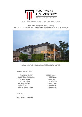
  • 1. SCHOOL OF ARCHITECTURE, BUILDING AND DESIGN BUILDING SERVICES (BLD 60903) PROJECT 1: CASE STUDY OF BUILDING SERVICES IN PUBLIC BUILDINGS KUALA LUMPUR PERFORMING ARTS CENTRE (KLPAC) GROUP MEMBERS: HOW SENG GUAN 1007P73021 JACKY TING SIM MING 0325286 LEE WAN XUAN 0325273 LEE SUK FANG 0323293 ALEXANDRA GO 0325342 WOO SHIR LEY 0317732 BAKHT JALAL KHAN 0326850 TUTOR: MR. AZIM SULAIMAN
  • 2. Page | 1 TABLE OF CONTENTS: ACKNOWLEDGEMENTS---------------------------------------------------------------------------------3 ABSTRACT-----------------------------------------------------------------------------------------------4 RESEARCH METHODOLOGY---------------------------------------------------------------------------5 1. INTRODUCTION OF KUALA LUMPUR PERFORMING ARTS CENTRE (KLPAC)--------------------------6 2. MECHANICAL VENTILATION SYSTEM---------------------------------------------------------8 2.1 Introduction-----------------------------------------------------------------------------------------9 2.2 Literature Review---------------------------------------------------------------------------------10 2.3 Case Study----------------------------------------------------------------------------------------13 2.4 Components of Mechanical Ventilation System----------------------------------------------14 2.4.1 Supply Air Diffuser/ Grille ------------------------------------------------------------14 2.4.2 Return/ Exhaust Air Grille ------------------------------------------------------------16 2.4.3 Fire Exhaust Fan ----------------------------------------------------------------------18 2.5 Conclusion-----------------------------------------------------------------------------------------19 3. AIR-CONDITIONG SYSTEM-------------------------------------------------------------------20 3.1 Introduction---------------------------------------------------------------------------------------21 3.2 Literature Review---------------------------------------------------------------------------------22 3.2.1 Types of Air-Conditioning System--------------------------------------------------22 a) Split Unit Air-Conditioning System---------------------------------------------- 22 b) Room Air Conditioner (Window Unit) --------------------------------------------23 c) Packaged Unit Air-Conditioning System-----------------------------------------24 d) Centralized/Plant Air-Conditioning System--------------------------------------25 3.3 Case Study----------------------------------------------------------------------------------------26 3.3.1 Centralized Air-Conditioning System -----------------------------------------------27 3.4 Components of Air Conditioning System------------------------------------------------------28 3.4.1 Air Handling Unit (AHU) --------------------------------------------------------------28 3.4.2 Fan Coil Unit (FCU) -------------------------------------------------------------------32 3.4.2.1 Type of Fan Coil Unit (FCU) ----------------------------------------------36 3.4.3 Ductwork ------------------------------------------------------------------------------37 3.4.4 Air-Cooled Chilled Water System --------------------------------------------------40 3.4.4.1Components of Air-Cooled Chilled Water System----------------------40 a) Evaporator -------------------------------------------------------------------------40 b) Compressor-------------------------------------------------------------------------41 c) Condenser ------------------------------------------------------------------------- 42 d) Expansion Valve ------------------------------------------------------------------- 43 3.5 Conclusion-----------------------------------------------------------------------------------------47
  • 3. Page | 2 4. FIRE PROTECTION SYSTEM------------------------------------------------------------------48 4.1 Introduction---------------------------------------------------------------------------------------49 4.2 Literature Review---------------------------------------------------------------------------------50 4.2.1 Active Fire Protection ---------------------------------------------------------------51 4.3 Active Fire Protection System ---------------------------------------------------------------- 52 4.4 Components of Fire Protection System ------------------------------------------------------53 4.4.1 Heat Detector ------------------------------------------------------------------------54 4.4.2 Smoke Detector ----------------------------------------------------------------------55 4.4.3 Call Point ------------------------------------------------------------------------------ 59 4.4.4 Fire Alarm Bell ------------------------------------------------------------------------ 62 4.4.5 Fire Alarm Control Panel ------------------------------------------------------------ 65 4.4.6 Dry Riser ------------------------------------------------------------------------------ 67 4.4.7 Fire Hydrant--------------------------------------------------------------------------- 69 4.4.8 Pump Room --------------------------------------------------------------------------- 70 4.4.9 Wet Riser and Hose Reel System ------------------------------------------------- 73 4.4.10 Sprinkler System ------------------------------------------------------------------- 75 4.4.11 Carbon Dioxide (CO2) Suppression System ----------------------------------- 77 4.4.12 Fire Extinguisher --------------------------------------------------------------------79 4.5 Passive Fire Protection System ---------------------------------------------------------------83 4.6 Components of Passive Fire Protection System --------------------------------------------84 4.6.1 Fire Wall -------------------------------------------------------------------------------84 4.6.2 Fire Rated Door ----------------------------------------------------------------------87 4.6.3 Smoke Curtain ------------------------------------------------------------------------ 91 4.6.4 Separation of Fire Risk Area ------------------------------------------------------- 92 4.6.5 Emergency Exit Signage ------------------------------------------------------------ 95 4.6.6 Fire Emergency Staircase ---------------------------------------------------------- 98 4.6.7 Automatic Ventilation Hatches ----------------------------------------------------101 4.7 Conclusion---------------------------------------------------------------------------------------102 5. MECHANICAL TRANSPORTATION SYSTEM----------------------------------------------103 5.1 Introduction-------------------------------------------------------------------------------------104 5.2 Literature Review-------------------------------------------------------------------------------105 5.2.1 Types of Lifts ----------------------------------------------------------------------- 106 5.3 Case Study--------------------------------------------------------------------------------------108 5.4 Components of Mechanical Transportation System----------------------------------------111 5.4.1 Machine Room ----------------------------------------------------------------------114 5.4.2 Control System ---------------------------------------------------------------------116 5.4.3 Overload and Fire Service Indicator ---------------------------------------------118 5.5 Drawings --------------------------------------------------------------------------------------- 119 5.6 Conclusion---------------------------------------------------------------------------------------122 6. REFERENCES --------------------------------------------------------------------------------123
  • 4. Page | 3 ACKNOWLEDGEMENTS First of all we would like to thanks to every individual for helping us to complete this report. Without their greatest effort in each task, we would not have the results today. Especially we would like to give the deepest gratitude to Mr. Selva, who is the facilities manager of Kuala Lumpur Performing Arts Centre (KLPAC). He showed his hospitality and kindness by taking his precious time for us to understand further more about the whole building services. We experienced the whole systems by being taken tour to every single place of the building, noted down what he explained to us and took the photos for the services systems used in KLPAC as well as the building itself. Secondly, we all want to thanks Mr. Azim, who is our lecturer for guiding us throughout the whole assignment by giving advice on how can we improve the content of this report to make it achieve clarity of information. Lastly, we would like to thank every member of this report who participate themselves in such a productive way, providing transportation for site visit as our report can be done within this short time. This photo is taken during our site visit on 22nd April 2017 for case study of this project and we also had an interview with the facilities manager of KLPAC, Mr. Selva.
  • 5. Page | 4 ABSTRACT This report will look in depth of the four main systems which are provided in the Kuala Lumpur Performing Art Centre (KLPAC) services. The four systems are mechanical ventilation system, air-conditioning system, fire protection system and mechanical transportation system. Each of the systems is branched out in more detailed components so that all of the building services systems explained in the report meet the requirements of Uniform Building By-Law 1984 (UBBL), Malaysian Standards Requirements (MS1525) and other rules and regulations. The conclusion of every main system will be conducted to show our understanding of these systems based on the documenting of the function of each building services, how it works, as well as the positions and requirements of different part components.
  • 6. Page | 5 RESEARCH METHODOLOGY In this report, we have used many types of research methodology to find the information of building services in our case study in order to complete this report. First, we went for the site visit consisting of 6 members to familiarize the building services they used in KLPAC. We observed and took photos of the variety types of building services they used. While Mr. Selva, who is the services manager of KLPAC were explaining to us, we quickly noted down what he has mentioned the system and took an audio record of the talk. Besides, we also asked few questions regarding to our report information. Unfortunately, we also faced the issue about the constraint of studies when we visited the site. There were several places which we were not allowed to enter or limitations for photos being taken. For example, the components of air-cooled chilled water system are hardly to take photos in the site, and we also cannot manage to take a closer look of fire hydrant in the site. So, our solution for this issue is to provide the similar examples of the services used and explained them how they work in our case study. After the site visit, we came back and create a shared folder to gather all the photos we have taken. Then, we categorized them into four main parts, which were mechanical ventilation, air-conditioning system, fire protection system and mechanical transportation. The purpose of doing it is to named and arranged the facilities/information orderly. We used several references such as internet, books including Uniform Building by Laws 1984 (UBBL) and Malaysian Building Requirements (MS1525) to complete this project. For identifying the building services we used in the case study were installed accurately, we used the UBBL and MS1525 to assist us. Other than that, we held meeting twice a week and had discussion with our tutor, Mr. Azim to ensure our report was on right track and informative.
  • 7. Page | 6 1. INTRODUCTION OF KUALA LUMPUR PERFORMING ARTS CENTRE (KLPAC) Image 1.1: The spectacular night view of the KLPAC. Kuala Lumpur Performing Arts Center (KLPAC) is located at Jalan Ipoh, Sentul West, Kuala Lumpur. Founded in 1995, where Faridah Merican and Joe Hasham created the first privately owned and operated theatre in Malaysia below Dataran Merdeka, called The Actor‟s Studio at Plaza Putra. However, flash floods in Kuala Lumpur destroyed the underground complex in 2003. In May 2004, Yayasan Budi Penyayang Malaysia, YTL Corporation Berhad and The Actors Studio Malaysia created a new jointly-owned platform to develop the performing arts, which became the Kuala Lumpur Performing Arts Centre (KLPAC) and has long opened its doors ever since May, 2005. Before KLPAC was built up, it was one of the southern region railway stations under YTL Corporation. Hence, warehouse was the only remaining building with the extension of tempered glass structure with beam supported it. KLPAC is a non-profit organization that fulfills the local art community needs by establishing centers for the performing arts in Malaysia. There are many performances scheduled
  • 8. Page | 7 throughout the years, mostly self-directed and self-organized events. Hence, the building has come up with several concepts such as transparent open space and „theatre for community‟. They intend to let everyone to approach the beauty of art hence the building is not build for VIP friendly, or public friendly. It is also well-known of its unique and interesting building structure with the combination of old and new elements. KLPAC consists of four levels with different functional spaces provided such as Pentas 1, Pentas 2, podium, studios, cafe, offices, small library and so on.
  • 9. Page | 8 MECHANICAL VENTILATION SYSTEM | KLPAC by Bakht Jalal Khan
  • 10. Page | 9 2. MECHANICAL VENTILATION SYSTEM 2.1 Introduction What is ventilation? It is referred as “The process of changing air in an enclosed space.” Stale, contaminated air in the indoors is replaced with fresh air from the outdoors. The use of mechanical devices to aid in this process is called mechanical ventilation. Mechanical ventilation systems circulate fresh air using ducts and fans, rather than relying on airflow through small holes or cracks in a home's walls, roof, or windows. Without mechanical ventilation to provide fresh air, moisture, odors, and other pollutants can build up inside a home. Image2.1: An overview of mechanical ventilation system.
  • 11. Page | 10 2.2 Literature Review Ventilation is necessary in buildings to remove „stale‟ air and replace it with „fresh‟ air:  Helping to moderate internal temperatures.  Helping to moderate internal humidity.  Replenishing oxygen.  Reducing the accumulation of moisture, odors, bacteria, dust, carbon dioxide, smoke and other contaminants that can build up during occupied periods.  Creating air movement which improves the comfort of occupants. Very broadly, ventilation in buildings can be classified as „natural‟ or „mechanical‟.  Mechanical (or forced) ventilation is driven by fans or other mechanical plant.  Natural ventilation is driven by pressure differences between one part of a building and another, or pressure differences between the inside and outside. Natural ventilation is generally preferable to mechanical ventilation as it will typically have lower capital, operational and maintenance costs. However there are a range of circumstances in which natural ventilation may not be possible:  The building is too deep to ventilate from the perimeter.  Local air quality is poor, for example if a building is next to a busy road.  Local noise levels mean that windows cannot be opened.  The local urban structure is very dense and shelters the building from the wind.  Privacy or security requirements prevent windows from being opened.  Internal partitions block air paths.  The density of occupation, equipment, lighting and so on creates very high heat loads or high levels of contaminants.
  • 12. Page | 11 Some of these issues can be avoided or mitigated by careful design, and mixed mode or assisted ventilation might be possible, where natural ventilation is supplemented by mechanical systems. Where mechanical ventilation is necessary it can be:  A circulation system such as a ceiling fan, which creates internal air movement, but does not introduce fresh air.  A pressure system, in which fresh outside air is blown into the building by inlet fans, creating a higher internal pressure than the outside air.  A vacuum system, in which stale internal air is extracted from the building by an exhaust fan, creating lower pressure inside the building than the outside air.  A balanced system that uses both inlet and extract fans, maintaining the internal air pressure at a similar level to the outside air and so reducing air infiltration and draughts.  A local exhaust system that extracts local sources of heat or contaminants at their source, such as cooker hoods, fume cupboards and so on. Typical mechanical ventilation systems for commercial buildings: In commercial developments, mechanical ventilation is typically driven by air handling units (AHU) connected to ductwork within the building that supplies air to and extracts air from interior spaces. Typically AHU comprise an insulated box that forms the housing for; filter racks or chambers, a fan (or blower), and sometimes heating elements, cooling elements, sound attenuators and dampers. In some situations, such as in swimming pools, air handling units might include dehumidification. It includes heating, cooling and humidity control, this can be referred to as Heating Ventilation and Air Conditioning (HVAC), extracting internal air and replacing it with outside air can increase the need for heating and cooling. This can be reduced by re-circulating a proportion of internal air with the fresh outside air, or by Heat Recovery Ventilation (HRV) that recovers heat from extract air to pre-heat incoming fresh air using counter-flow heat exchangers. The design of mechanical ventilation systems is generally a specialist task, undertaken by a building services engineer. Whilst there are standards and rules of thumb that can be
  • 13. Page | 12 used to determine air flow rates for straight-forward situations, when mechanical ventilation is combined with heating, cooling, humidity control and the interaction with natural ventilation, thermal mass and solar gain, the situation can quickly become very complicated. This, along with additional considerations, such as the noise generated by fans and the impact of ductwork on acoustic separation means it is vital building services are considered at the outset of the building design process, and not seen as an add-on.
  • 14. Page | 13 2.3 Case Study Roaming around inside the walls of the KLPAC building, many components of the mechanical ventilation system can be seen actively involved in the process of air exchange. Upon further inspection, the main components present include the Supply Air Diffusers, Return Air Grille, and the Fire Exhaust fan. The design for the KLPAC building fails to allow a significant pathway for natural ventilation to take place. Many of the rooms are tucked well within the building while a vast number of people aid the buildup of stale air and increase temperature. The Supply and Exhaust Grilles help provide and fresher flow of air and keep the temperature low in order to tackle this problem, a characteristic of tropical climate.
  • 15. Page | 14 2.4 Components of Mechanical Ventilation System 2.4.1 Supply Air Diffuser/ Grille Many of these components can be seen visible around the main lobby and various other parts of the buildings. Some are protruding outwards from the walls while some fixed on the interiors. Some are being round in shape while others being rectangular. The designers seem to have engaged the aesthetic properties of these components as parts of their designs. Image2.2 Image2.3 Image2.2 and Image3.3: Showing Round Supply Air Diffusers at main lobby KLPAC. The Supply Air Diffusers are connected to the interior ends of the duck system. These ducks create and network of passage ways for the air to travel across the building. A second set of Supply Air Grilles can also be found behind the seats in the performance stage room. These are different in shape, rectangular, however perform the same function. A diffuser is a device for reducing the velocity and increasing the static pressure of a fluid passing through a system”. Diffusers are used to slow the fluid's velocity while increasing its static pressure. The fluid's static pressure rise as it passes through a duct is commonly referred to as pressure recovery. In contrast, a nozzle is often intended to increase the discharge velocity and lower pressure while directing the flow in one particular direction.
  • 16. Page | 15 A typical, subsonic diffuser is a duct that increases in size in the direction of flow. As the duct increases in size, fluid velocity decreases, and static pressure rises. Both mass flow rate and Bernoulli's principle are responsible for these changes in pressure, and velocity.
  • 17. Page | 16 2.4.2 Return/ Exhaust Air Grille Image2.4 Image2.5 Image2.4 and Image2.5: Showing the Return Air System at KLPAC As explained earlier, as the internal air becomes contaminated and unwanted, it needs to be removed and refreshed. The function of this component is to expel the stale out from the places within the walls. This component is also covered with a grill so in order to prevent damaging obstacles from entering. Behind the grill, a filter is often installed. This filter serves its expertise in treating the air while passing through. It is believed that apart from expelling stale air out, the Return system can also help in decreasing the temperature of the room as the stale air in generally higher in temperature compared to fresh air. Image2.6 Image2.7 Image2.6 and Image2.7: Showing the Duct Work System and Return Air Fan respectively.
  • 18. Page | 17 For this reason, Return fans can also be found in rooms with machines that generate heat energy such as the lift engine rooms. Air from the Return system also travels through the duct works.
  • 19. Page | 18 2.4.3 Fire Exhaust Fan Image2.8: Showing Fire Exhaust Fans outside of KLPAC. In the case of a fire hazard taking over the building, the best suggested action is to evacuate the building as soon as possible. However this may not prove to be so easy and thus other alternatives have to be worked out to aid in such a situation. The main hazards present in case of a fire are of course unbearable heat itself, along with dark harsh smoke and poisonous gas. The main function of the Fire Exhaust fan is to expel the built up gas and smoke, along with some of the heat, as best as it possibly can in order to buy more time for the people to evacuate. Powerful fans help create a change in pressure that directs the smoke and gas towards the outside. Those unwanted gases travel through another system of duct works, consisting of fire dampeners. It is important for all these components to be fire proof to prevent failure of the system.
  • 20. Page | 19 2.5 Conclusion If there‟s only one thing our team achieved from this project, it‟s the realization of the importance of the Mechanical ventilation system. It provides architects with a chance to explore further in designing, free of the limitation sanctioned by design characteristics of natural ventilation. The Whole system of Mechanical ventilation serves as the lungs within the body of the building. Bringing in fresh air and expelling the contaminated one. The body would instantly suffocate to death with its absence. It is costly and maintenance requiring system. But a system without which living in most of the buildings present is impossible.
  • 21. Page | 20 AIR-CONDITIONING SYSTEM | KLPAC by JACKY TING & HOW SENG GUAN
  • 22. Page | 21 3.AIR-CONDITIONING SYSTEM 3.1Introduction Thermal comfort and good indoor air quality is a necessity for occupants dwelling in an indoor space of a building. Heating, Ventilating and Air-conditioning also known as HVAC was introduced as a mechanical technology that is able to provides acceptable indoor air quality and achieve adequate, continuous and reliable thermal comfort to a building‟s indoor environment. Through mechanical engineering combined with the principles of thermodynamics, fluid mechanics and heat transfer to a particular space, the HVAC is able to generate heat, change or replace air in a space and control temperature and the cooling and humidity control within a space. The Kuala Lumpur Performing Art Centre (KLPAC), utilizes the use of mechanical ventilation and air-conditioning system to create a comfortable and cool environment for its occupants, both the staffs and visitors. The KLPAC uses centralized air-conditioning system as their air- conditioning system.
  • 23. Page | 22 3.2 Literature Review Air-Conditioning System Air-Conditioning is the process of controlling the air movement and air conditions, specifically in terms of temperature, humidity, and cleanliness of the air, the factors that help in achieving the thermal comfort in an interior environment. The basic principle for air-conditioning is that it is an exchange of indoor and outdoor air, whereby it extracts heated indoor air and sends it outdoors, and on the other end, takes in outdoor air, treats it, then provides it to the indoor space. 3.2.1 Types of Air-Conditioning System The four types of air-conditioning system which are: a) Split Unit Air-Conditioning System Comprised of two different parts, an indoor and an outdoor unit. The indoor unit, installed with the evaporator, air filter, cooling coil and blower fan and the outdoor unit would have the compressor, expansion valve and condenser. The sequence of the air flow exchange is warm air will be brought in by the blower, cooled and treated by the evaporator and the filter. Within the outdoor unit, heat is removed through the compressor and condenser. Image3.1 Image3.2 Image3.1and Image3.2: Showing Split Unit Air-Conditioning System Diagram and Split Unit Air-Conditioning System Components respectively.
  • 24. Page | 23 b) Room Air Conditioner (Window Unit) The simplest air-conditioning system amongst the four categories. This system is most suited for the use for a space rather than a whole building. The system is installed at window openings or on the wall. Using this method, the air of the space will be cooled down when the fans blow over 20 the evaporator and the heat is transferred from the inside to outside by the condenser. Image 3.3 Image 3.4 Image 3.3 and Image 3.4: Showing Room Air-Conditioning System Diagram and Room Air- Conditioner respectively.
  • 25. Page | 24 c) Packaged Unit Air-Conditioning System Packaged unit air-conditioning system comes in a ducted or ductless system that is often used in larger scale building. The system comprises of two separate parts which is the condensing unit and evaporative unit. Condensing unit which is placed in the interior while evaporative unit is placed outdoors. This system provides heat on a cold climate by reversing the refrigerant flow to heat the interior and transfer heat from the exterior. Image3.5 Image3.6 Image3.7 Image3.5, Image3.6 and Image 3.7: Showing Packaged Air-Conditioning System Diagram, Packaged Air-Conditioner (Ducted) and Packaged Air-Conditioner (Ductless) respectively.
  • 26. Page | 25 d) Centralized/Plant Air-Conditioning System Centralized/Plant air-conditioning system is that effectively allocates cool air circulation to designated spaces to ensure the appropriate air is given to the whole building. The system used central plant, water system and air system. Cool air is spread through a system of supply and return ductwork that brings cool airs from air conditioner to the building. The ductwork can be identified by having grill covers installed along the supply line located on the walls or ceilings. The 3 subsystems of centralized air-conditioning system are: i) Air delivery system ii) Chilled water system iii) Heat rejection system Image3.8 Image3.9 Image3.8 and Image3.9: Showing Centralized Air-Conditioning System Diagram and Centralized Air-Conditioning Plant respectively.
  • 27. Page | 26 3.3 Case Study KLPAC, known as a platform for performing arts to be showcase, consists of multiple areas that cater for different functions. Using centralized air-conditioning system to provide a comfortable environment, it‟s occupants are able to stay for longer periods of time especially for during long performances. Through our analysis on the KLPAC, we have identified that the building uses two type of unit air-conditioning as the air-conditioning systems. The Air Handling Units (AHU), a compound system that supplies air to large space/area by channeling air through ducting systems. Then there is the Fan Coil Units (FCU), ductless system that is used in smaller spaces. The factor which determines the type of air-conditioning required is based on the type, function, occupants, and the volume of the space/room. There are a total of 5 AHUs and several FCUs that are used to control the air of the building. The Air Handling Units (AHUs) are mainly installed for the main theatre in considerations to its users, volume, and function. 4 AHUs were considered to be the best to provide the optimum comfort conditions for a capacity of 500 people, the theatre‟s large spatial volume, and to improve the duration that the viewers are able to stay in the main theatre. The remaining AHU is installed in the experimental theatre because the consideration amount is less as compared to the main theatre. The Fan Coil Units (FCU) are installed in the smaller rooms such as the dressing rooms, studios, offices or cafeteria to provide concentrated cooling to the individual rooms. Both the AHUs and FCUs are channeled with treated air that it cooled in the air-cooled chiller system through the process of refrigerant cycle. It‟s the process that demonstrates how the refrigerant vapor is absorbed and released by the compressor to the condenser. Air-cooled chiller system is used in the building rather than using cooling tower because it absorbs heat from the indoor space and discards it to the surrounding.
  • 28. Page | 27 3.3.1 Centralized Air-Conditioning System Both AHU and FCU are centralized air-conditioning systems. This means that they serve multiple spaces in the building from a base where a chiller produces chilled water and sends it towards the designated air-handling units (AHU) or fan-coil unit (FCU) in the building through air distribution ducts. This has proven to be a high energy efficiency system, hence the centralized air-conditioning system is often used in large buildings with the system mainly focused on conditioning the outdoor air and achieving the indoor temperature needs by the allocation of conditioned air to the particular space. Advantages and disadvantages of centralized air-conditioning system: Advantages: - Higher energy efficiency - Better control of comfort levels - Greater load management potential - Larger coverage area - Usage flexibility Disadvantages: - High installment cost - Maintenance complexity
  • 29. Page | 28 3.4 Components of Air Conditioning System 3.4.1 Air Handling Unit (AHU) Air-handling unit (AHU) is an air management dock encased in a large metal box consisting of the humidifier, air filter, blower fan and cooling & heating coils. It task is to distribute the incoming cool air towards specific rooms of a building through air ducting. These air received undergo treatment in filtering, heating, cooling and recycling part of the existing indoor air. The AHU is usually situated in a room size roughly 3% of the floor area services by the AHU. In the KLPAC, the AHUs are placed in individual surround rooms to ensure no external forces or pressure is applied on itself. For energy conservation, the AHU in KLPAC is also equipped with a manual control to save energy during times when the AHU is not in use. Image3.10 Image3.11 Image3.10 and Image 3.11: Showing Centralized Air-Conditioning System Diagram and Centralized Air-Conditioning Plant respectively.
  • 30. Page | 29 MS1525, Code 8.4.2.1, control setback and shut-off states that each system should be equipped with a readily accessible means of shutting off or reducing the energy used during periods of non-use or alternate uses of the building spaces or zones served by the system Image 3.12 Image 3.12: Showing location of Air Handling Unit (AHU) in Ground Floor. Image3.13 Image 3.13: Showing location of Air Handling Unit (AHU) in First Floor.
  • 31. Page | 30 Image3.14 Image3.14: Showing location of Air Handling Unit (AHU) in Second Floor. Image3.15 Image3.15: Showing location of Air Handling Unit (AHU) in Second Floor.
  • 32. Page | 31 Analysis: The KLPAC has fulfilled the requirements of the Malaysian Standard Code of Practice on Energy Efficiency and Use of Renewable Energy (MS 1525) whereby the AHU was installed nearby control rooms which enabled for a person in charge to shut off and reduce the energy to any space that is not in use.
  • 33. Page | 32 3.4.2 Fan Coil Unit (FCU) Image3.16 Image3.17 Image3.16 and Image3.17: Showing Ceiling mounted Fan Coil Unit in studio, KLPAC and FCU‟s control panel respectively. A Fan Coil Unit (FCU) is a simpler air-conditioning device compared to air handling unit (AHU). It consists of a heating or cooling coil and fan. It is part of an HVAC system which can be found in residential, commercial or industrial buildings. Normally FCU is not connected to ductwork. FCU is flexible to be installed and because of this reason, it is more economical to install compare to those ducted air-conditioning system. It is used to control the temperature in the installed space or sometimes for multiple smaller spaces. There are two ways to control the FCU, which are either by manually on or off switch or by thermostat.
  • 34. Page | 33 Image3.18: Showing location of FCU in Ground Floor Plan KLPAC. Image3.19: Showing location of FCU in First Floor Plan KLPAC.
  • 35. Page | 34 Image3.20: Showing location of FCU in Second Floor Plan KLPAC. Image3.21: Showing location of FCU in Third Floor Plan KLPAC.
  • 36. Page | 35 In KLPAC, the FCU are ceiling mounted. The spaces that are using FCU included studio, offices, conference room, bistro and bar, shops and lobby area. For the control panel, it is located specifically at the spaces where the FCU are installed so that people can operate the machines freely to achieve better comfort level when they are using the space. MS 1525 code 8.4.4.1, Off-hour control. “ACMV system should be equipped with automatic controls capable of accomplishing a reduction of energy use for example through equipment shutdown during periods of non-use or alternative use of the spaces served by the system.”
  • 37. Page | 36 3.4.2.1 Type of Fan Coil Unit (FCU): Type 1 - Two-pipe fan coil units This type of FCU has only one supply and one return pipe. So it can only supply either cold or hot water to the unit depending on the situation needed. For example different time of year has different temperature, so FCU works according to the needs. In winter it is usually in heating mode and cooling mode in summer. This type of FCU is not suitable for high internal heat gains spaces such as computer room. Type 2 - Four-pipe Fan Coil Unit It has two supply pipes and two return pipes. This allows both hot and cold water can enter the unit at any given time. This type of FCU is important because sometimes the required temperature for different areas of a building might be different. So due to the differences of internal heat loss and gain of all spaces, to encounter this problem, four-pipe FCU is commonly used. Differences between air handling unit and fan coil unit 1. AHU is generally a bigger system than FCU. 2. AHU is more complex than FCU and that AHU are often used in bigger establishments or spaces. 3. AHU system usually channels air through ducts whereas the FCU don‟t have any ductworks. 4. AHU system treats outside air while FCU basically recycle or re-circulates the air. 5. AHU has sections for reheating and humidifying whereas the FCU does not have any. 6. FCU is often more noisier than AHU.
  • 38. Page | 37 3.4.3 Ductwork Image3.22 Image3.23 Image3.22 and Image3.23: Showing the ductwork installed in KLPAC. Ductwork is used for the forced transportation of air in heating, ventilation, and air- conditioning which so called HVAC in short. Pipes used to transfer water, gas or refrigerant are not ductwork because ductwork only moves air. Ductwork is to channel air towards the room or to the air from room towards the outside. It allows the air to circulate and allow a better indoor air quality. Ductwork also has different types of shapes such as rectangular, round, and oval cross-sectional shapes. Sometimes the shapes can even be combined. The construction materials for ductwork are ranging from metal, to fiberglass and even flexible plastics. In KLPAC, the ductwork is mostly in rectangular and round shape. Image3.24 Image3.25 Image3.26 Image3.24, Image3.25 and Image3.26: Showing Oval Cross-sectional Duct, Rectangular Duct and Round Duct respectively.
  • 39. Page | 38 Image3.27: Showing the ductwork is covered with fiber. The ductwork in KLPAC is covered with a layer of fiber. This is to prevent condensation of water which will increase the moisture of the room. It‟s also for safety purpose like slippery floor. Issues of poor ductwork maintenance 1. Dirt and dust covered surface 2. Poor indoor air quality 3. Higher heating and cooling bills 4. Low comfort level in the space Causes of Ductwork problems 1. Installation If the system didn‟t install in the correct way, it might not be able to heat and cool a space effectively and efficiently. During the installation, if it‟s not sealed properly, leaking ductwork will be one of them problem too. 2. Pest damaged ductwork Ductwork damaged by animals or insects can result in loss of conditioned air to poor indoor air quality. So checking and maintenance process must be done more frequently. 3. Dirty air ducts Dirty air ducts can distribute pollen and dirt throughout a space. To protect the indoor air quality, the ductwork must be inspected for possible contamination and cleaned when necessary.
  • 40. Page | 39 According to MS 1525 code 8.6, Air handling duct system insulation “All ducts, plenum and enclosures installed in or on buildings should be adequately insulated to prevent excessive energy losses. Additional insulation with vapour barriers may be required to prevent condensation under some conditions.” According to MS 1525 code 8.6, Air handling duct system insulation “All ducts, plenum and enclosures installed in or on buildings should be adequately insulated to prevent excessive energy losses. Additional insulation with vapour barriers may be required to prevent condensation under some conditions.”
  • 41. Page | 40 3.4.4 Air-Cooled Chilled Water System Image3.28 Image3.29 Image3.28 and Image3.29: Showing Air-Cooled Chilled Water System of KLPAC and Diagram of how Air-Cooled Chilled System works. Air-cooled chilled water system is a refrigerant system that removes heat contained in the chilled water. The components of air-cooled chilled water system are evaporator, compressor, condenser and expansion valve. 3.4.4.1Components of Air-Cooled Chilled Water System a) Evaporator Image3.30: Showing Evaporator.
  • 42. Page | 41 The function is to provide a heat-absorbing surface. It is a coil pipe where the refrigerant inside it is vaporizing and absorbing heat. The air blown over the surface of this pipe is cooled. There are three factors that will affect the design of the evaporator, which are: (i) Pressure Drop - It must have sufficient space for the circulation of the refrigerant without too much pressure drop between inlet and the outlet. (ii) Temperature - The evaporator must have enough surface to absorb the required heat load in order to ensure the temperature difference between the substance being cooled and the refrigerant is not excessive. (iii) Liquid and Refrigerant vapor - Evaporator must have enough spaces for the liquid refrigerant and the vapor to separate from the liquid. b) Compressor Image 3.31 Image3.32 Image3.31 and Image3.32: Showing Piston Compressor and Scroll Compressor. Compressor is the heart of cooling cycle. Compressor‟s function is to compress the refrigerant vapor from the evaporator and pumps the refrigerant throughout the system. Refrigerant vapor enters the compressor through the suction valve and fills the cylinder. The refrigerant is cool but it absorbs heat in the evaporator. Most of the heat is absorbed while it was changing state from liquid to a vapor. There are two types of compressors, which are: (i) Piston Compressor - uses pistons attached to a motor driven crankshaft to draw in and compress refrigerant
  • 43. Page | 42 (ii) Scroll Compressor - uses and orbiting scroll on an eccentric motor driven crankshaft to suck in vaporized refrigerant and push it into a stationary scroll whose volume gradually decreases to compress the refrigerant. c) Condenser Image 3.33: Showing Condenser. Condensers‟ function is to reject the heat absorbed by the evaporator. The refrigerant changes from vapor to liquid in the condenser. While this state of changes occurring, a large amount of heat is rejected. There are three types of condensers used in HVAC: (i) Air-cooled - Eject heat to outdoors and has simpler installation method. Most commonly used by freezers and residential air-conditioning units. (ii) Water-cooled - More pricey to install but more efficient. Commonly used for swimming pools and condenser pipe for city water flow. Must be maintained and serviced frequently. To avoid corrosion and growing of algae, makeup water is constantly supplied along with water treatment. (iii) Evaporative (Combined) - Operate at a low condensing temperature. It is used in large commercial air-conditioning units. Effective but might not be the most efficient depends on the uses.
  • 44. Page | 43 d) Expansion Valve Image 3.34 Image 3.35 Image 3.34 and Image 3.35: Showing Expansion Valve and Sectional Diagram of Expansion Valve. Expansion valve helps to remove pressure from the liquid refrigerant to allow expansion or change of state from a liquid to vapor in the evaporator. Pressure at the inlet and outlet of the expansion valve will closely approximate gauge pressures at the inlet and outlet of the compressor in most of the systems. The similarity of pressure is caused by the closeness of the components to each other. There are two types of valves are used in the air conditioning machine systems: (i) Internally-equalized valve (ii) Externally-equalized valve
  • 45. Page | 44 Image 3.35: Showing Air-Cooled Chilled System and Piping, KLPAC. Image 3.36: Showing Schematic diagram of air-cooled chilled water system Image 3.37: Showing Location of Air-Cooled Chilled Water System, KLPAC KLPAC has two air-cooled chilled water system which are placed outside of the main building. This is because the machines will produce noise and may disturb the events conducting in the building. The chillers are connected to AHU to circulate the chilled water. The control panel is located in the room beside it so that manual adjustment can be made.
  • 46. Page | 45 How Air-Cooled Chilled Water System Works? First step of the cycle is begins in the evaporator where a liquid refrigerant flows over the evaporator tube bundle and evaporates. It absorbs heat from the chilled water circulating through the bundle. Then the refrigerant vapor is drawn out from the evaporator by the compressor. Compressor pumps the refrigerant vapor to the condenser by raising its pressure and temperature. The high pressure liquid refrigerant from the condenser then passes through the expansion valve that reduces the refrigerant pressure and temperature as it enters the evaporator. Lastly the refrigerant flows over the chilled water coils absorbing more heat and completing the cycle. Chilled water pump Image 3.38 Image 3.39 Image 3.38 and Image 3.39: Showing Chilled Water pump and location of chilled water pump, piping and control panel room respectively. Chilled water pump returns warm chilled water to the chiller and pump chilled water to every AHU room.
  • 47. Page | 46 Piping system Image 3.40: Showing piping of Air-Cooled Chilled Water System. The pipes from chiller are connected to the cooling coil in AHU. The pipe carries in cool water which works as cooling element that will cool the air going through AHU. In KLPAC, these piping are located underground of the control panel and chilled water pump room. According to MS 1525 code 8.5, Piping Insulation “All piping installed to serve building and within building should be adequately insulated to prevent excessive energy losses. Additional insulation with barriers may be required to prevent condensation under some conditions.”
  • 48. Page | 47 3.5 Conclusion KLPAC has wisely made the choices between FCU and AHU for each space so that there is no waste of energy or inefficient use of the system and also the positioning of all the piping and machines very thoughtful too because they want to avoid any disturbance inside the performing area. KLPAC also has a GenSet functions to supply electricity for AHU when there is any sudden electricity cut-off during the stage performances because KLPAC relies heavily on air-conditioning in performing stage 1 and also performing stage 2.
  • 49. Page | 48 FIRE PROTECTION SYSTEM | KLPAC by LEE WAN XUAN & WOO SHIRLEY
  • 50. Page | 49 4. FIRE PROTECTION SYSTEM 4.1 Introduction In this research paper, Active Fire Protection and Passive Fire Protection in Kuala Lumpur Performing Arts Centre (KLPAC) are being studied and explained. Both fire safety system is discussed and compared to the rules and regulation in the Uniform Building By-Laws (UBBL) 1984. Finally recommendation and improvement are also suggested. It also had concluded the analysis. Fire protection is very important, because it safeguard your life, preserve materials assets and the environment from devastation.
  • 51. Page | 50 4.2 Literature Review Fire protection systems are one of the important features to be put in every building‟s design and construction. In the event of a fire outbreak, the fire protection system ensures that the building is equipped and capable of controlling and extinguishing the fire. The fire protection system is divided into two part known as the Active Fire Protection System (AFPS) and the Passive Fire Protection System (PFPS). Both components are further divided into their individual sub-components and each with different characteristics and functions.
  • 52. Page | 51 4.2.1 Active Fire Protection Active Fire Protection is a group of systems that require some amount of action or motion in order to work efficiently in the event of a fire. Actions may be manually operated, like a fire extinguisher or automatic, like a sprinkler, but either way they require some amount of action. Active Fire Protection system includes fire suppression system, fire sprinkler system and fire detection system. Fire suppression system is used to control or extinguish fire, either manually or automatically. Manual control includes the use of a fire extinguisher or a standpipe system. Automatic control means can include a fire sprinkler system, a gaseous clean agent, or firefighting foam system. Fire sprinkler systems are installed in all types of buildings, commercial and residential. They are usually located at ceiling level and are connected to a reliable water source, most commonly city water. A typical sprinkler system operates when heat at the site of a fire causes a glass component in the sprinkler head to fail, thereby releasing the water from the sprinkler head. This means that only the sprinkler head at the fire location operates – not all the sprinklers on a floor or in a building. Sprinkler systems help to reduce the growth of a fire, thereby increasing life safety and limiting structural damage. Fire detection system includes smoke detector, flame detector and heat detector, and an alarm is sounded to enable emergency evacuation as well as to dispatch the local fire department. Where a detection system is activated, it can be programmed to carry out other actions.
  • 53. Page | 52 4.3 Active Fire Protection System The flowchart below shows the active fire protection system protocol in KLPAC.
  • 54. Page | 53 4.4 Components of Active Fire Protection System 4.4.1 Heat Detector Image 4.1: Showing Heat detectors found in KLPAC. UBBL SECTION 225. (1) Every building shall be provided with means of detecting and extinguishing fire and with fire alarms together with illuminated exit signs in accordance with the requirements as specified in the Tenth Schedule to these By-laws. Heat detector is a fire alarm device that reacts to the increase in temperature by the convected thermal energy of a fire. It contain a heat sensing circuit that can sense a rapid increase in room temperature, then issue a signal to a fire alarm control panel as part of the fire alarm system. There are two main types of heat detectors: “rate-of-rise” and “fixed temperature”. The type of heat detector that KLPAC used is fixed temperature heat detector. The heat detector composed of a heat sensitive eutectic alloy which will change from a solid to liquid when it reaches the eutectic point. It will be triggered when the surrounding temperature reaches the eutectic point, which is usually 58°C, and then send a signal to the fire alarm control panel.
  • 55. Page | 54 Image 4.2: Showing diagram of reaction of heat detector. Image 4.3: Showing Red circles indicate the locations of heat detectors in ground floor.
  • 56. Page | 55 4.4.2 Smoke Detector Image 4.4: Showing the example of smoke detector. UBBL SECTION 225. (1) Every building shall be provided with means of detecting and extinguishing fire and with fire alarms together with illuminated exit signs in accordance with the requirements as specified in the Tenth Schedule to these By-laws. Besides heat detector, smoke detector is also part of the fire alarm system which will send a signal to the fire alarm control panel when it senses the presence of smoke. Smoke alarms will detect fires more rapidly than heat detectors. There are three types of smoke alarms: ionization, photoelectric and combination. KLPAC have the ionization smoke alarm and photoelectric smoke alarm, the ionization smoke alarm is commonly found inside of the building while the photoelectric smoke alarm only found in 3rd floor. Ionization alarms use a small amount of radioactive material to ionize the air in the sensing chamber. The air chamber will then permit current to flow between two charged electrodes. When smoke enter the chamber, it interrupts the current and setting off the alarm. Photoelectric smoke alarms made up of a light emitting diode and a light sensitive sensor in the sensing chamber. When smoke particles enter the chamber, the light beam will be scattered. This scattered light is detected and sets off the alarm.
  • 57. Page | 56 Image 4.5: Showing diagram of reaction of Photoelectric Smoke Detector and Ionization Smoke Detector. Image 4.6: Showing Red circles indicate the locations of smoke detectors in ground floor.
  • 58. Page | 57 Image 4.7: Showing Red circles indicate the locations of smoke detectors in first floor. Image 4.8: Showing Red circles indicate the locations of smoke detectors in second floor.
  • 59. Page | 58 Image 4.9: Showing Red circles indicate the locations of smoke detectors in third floor.
  • 60. Page | 59 4.4.3 Call Point Image 4.10: Showing Call Point found in KLPAC. Call point is a manual fire alarm activation which connected to a central fire alarm panel and sound the evacuation alarm for the relevant building or zone in case there is any fire or emergency exist. Manual fire alarm activation requires human intervention, as distinct from automatic fire alarm activation such as that provided through the use of heat detectors and smoke detectors. It is, however, possible for call points to be used in conjunction with automatic detection as part of an overall fire detection and alarm system. The minimum height of the call point is 1500mm from ground level, so that a disabled user can easily reach it. The call point is usually located near a fire extinguisher or a hose reel system so that the people can take action as soon as possible in case they have spotted and signaled an occurrence of fire.
  • 61. Page | 60 Image 4.11: Showing Red circles indicate the locations of call points in ground floor. Image 4.12: Showing Red circles indicate the locations of call points in first floor.
  • 62. Page | 61 Image 4.13: Showing Red circles indicate the locations of call points in second floor Image 4.14: Showing Red circles indicate the locations of call points in third floor.
  • 63. Page | 62 4.4.4 Fire Alarm Bell Image 4.15: Showing fire alarm bell found in KLPAC UBBL SECTION 237 1. Fire alarms shall be provided in accordance with the Tenth Schedule to these By-laws. 2. All premises and buildings with gross floor area excluding car park and storage areas exceeding 9290 square meters or exceeding 30.5 meters in height shall be provided with a two stage alarm system with evacuation (continuous signal) to be given immediately in the affected section of the premises while an alert (intermittent signal) be given in adjoining section. 3. Provision shall be made for the general evacuation of the premises by action of a master control. Fire alarm bell is a device that generates loud alert sound to give warning of a fire. When a fire or an emergency has been detected and verified, the fire alarm control panel will supply energy to the fire alarm, the motorized alarm bell will then produce sound to inform the occupants of the need to take action. The fire alarm bell remains the most commonly used
  • 64. Page | 63 alarm for fire evacuation systems because the alarm bells deliver high sound pressure output for fire signaling needs while having an extremely low power consumption. Image 4.16: Showing Red circles indicate the locations of fire alarm bells in ground floor. Image 4.17: Showing Red circles indicate the locations of fire alarm bells in first floor.
  • 65. Page | 64 Image 4.18: Showing Red circles indicate the locations of fire alarm bells in second floor. Image 4.19: Showing Red circles indicate the locations of fire alarm bells in third floor.
  • 66. Page | 65 4.4.5 Fire Alarm Control Panel Image 4.20 Showing fire alarm control panel in KLPAC. UBBL SECTION 238 Every large premises or building exceeding 30.5 meters in height shall be provided with a command and control center located on the designated floor and shall contain a panel to monitor the. Public address, fire brigade communication, sprinkler, water flow detectors, fire detection and alarm systems and with a direct telephone connection to the appropriate fire station bypassing the switchboard. A Fire Alarm Control Panel is the controlling component of the Fire Alarm System. The panel receives signals from the environmental sensors by cause of the presence of smoke or fire, monitors their operational integrity and provides for automatic control of equipment, and transmission of information necessary to prepare the facility for fire based on a predetermined sequence. The panel may also supply electrical energy to operate any associated sensor, control, transmitter, or relay.
  • 67. Page | 66 The control panel that KLPAC used is addressable panel. Addressable Fire Alarm Control Panel employs one or more Signaling Line Circuits, which can monitor and control several hundred devices. Common addressable input devices include smoke detectors, heat detectors, manual call points, fire sprinkler system inputs, etc. Image 4.21: Showing Red rectangle indicates the locations of fire alarm control panel in ground floor.
  • 68. Page | 67 4.4.6 Dry Riser Image 4.22: Showing example of dry riser. UBBL SECTION 230 (1) Dry rising systems shall be provided in every building in which the topmost floor is more than 18.3 meters but less than 30.5 meters above fire appliance access level. (2) A hose connection shall be provided in each firefighting access lobby. (3) Dry risers shall be of minimum "Class C” pipes with fittings and connections of sufficient strength to withstand 21 bars water pressure. (4) Dry risers shall be tested hydrostatically to withstand not less than 14 bars of pressure for two hours in the presence of the Fire Authority before acceptance. (5) All horizontal runs of the dry rising systems shall be pitched at the rate of 6.35 millimeters in 3.05 meters. (6) The dry riser shall be not less than 102 millimeters in diameter in buildings in which the highest outlet is 22.875 meters or less above the fire brigade pumping inlet and not less than 152.4 millimeters diameter where the highest outlet is higher than 22.875 meters above the pumping inlet.
  • 69. Page | 68 A dry riser is an empty pipe that can be externally connected to a pressurized water source by firefighters. Unlike wet riser that is always full of water, dry riser is empty when not in use. It is a vertical pipe used for water distribution to multiple levels of a building or structure as a component of the fire suppression systems. Dry risers are used if only the building‟s topmost floor is more than 18.3 meters, where the water pressure of the building not enough for fire suppression. It is connected with an inlet connection for the firefighters to connect their engine pump. The breeching inlet where the firemen will pump water into it is also needed to be provided at ground level and connected to the bottom of the dry riser pipe.
  • 70. Page | 69 4.4.7 Fire Hydrant Image 4.23: Showing Fire hydrant found in KLPAC UBBL Section 225. (2) Every building shall be served by at least one fire hydrant located not more than 91.5 meters from the nearest point of fire brigade access. A fire hydrant is a connection point of the fire hydrant pump system by which firefighters can tap into a water supply. Fire hydrant pump systems are high pressure water pumps designed to increase the firefighting capacity of a building by boosting the pressure in the hydrant service when mains is not enough for fire suppression. The fire hydrants at KLPAC are placed at an empty outdoor area besides the building for the ease of firefighter to work. Image 4.24: Showing Red circles indicate the locations of fire hydrants in ground floor.
  • 71. Page | 70 4.4.8 Pump Room Image 4.25: Showing fire pumps inside and beside of the pump room in KLPAC. The pump room is a room dedicated to the mechanical equipment of water pump and fire pump. A fire pump is a part of a fire sprinkler system's water supply and powered by electric, diesel or steam, it is usually located at the lower ground. The pump intake is either connected to the public underground water supply piping, or a static water source like tank or lake. Firefighting system comprised of two main pumps, one driven by an electric motor and another one by diesel engine. An auxiliary jockey pump is used to connect the pumps to fire hydrants and sprinkler system. The jockey pump serves as a small Flow Multistage Pump, which used to maintain the required pressure of the main pumps, the operation of jockey pump is controlled through pressure switches automatically. The pump provides water flow at a higher pressure to the sprinkler system risers and hose standpipes, by either manually or automatically. In an automatic system, the fire pump initiate when the pressure in the fire sprinkler system experience a sudden drop below a threshold, or the pressure drop in the firefighting main when the other fire hose reels or other firefighting connections are opened. The main pumps can only be stopped manually. This system is known as packaged system.
  • 72. Page | 71 Image 4.26: Showing different type of pump (from left to right) : Duty pump, Jockey Pump (small and green in colour), Standby pump. Image 4.27: Showing diagram showing the layout of a pump room. The fire pump room plays an important part in the active fire protection system in KLPAC, because it holds the wet riser and hose reel system and the fire sprinkler system in KLPAC. These systems will only function with the existence of the pumps.
  • 73. Page | 72 Image 4.28: Showing Red rectangle indicates the locations of pump room in ground floor.
  • 74. Page | 73 4.4.9 Wet Riser and Hose Reel System Image 4.29: Showing hose reel system found in KLPAC. UBBL Section 231. (1) Wet rising systems shall be provided in every building.in which the topmost floor is more than 30.5 meters above fire appliance access level. (2) A hose connection shall be provided in each firefighting access lobby. The hose reel system serves as an firefighting aid at the early stage of fire. The system consists of pumps, pipes, water supply and hose reels located strategically in a building, ensuring proper coverage of water to combat a fire risk. Wet riser is installed in a building for fire-fighting purposes and permanently charged with water from a pressurized supply, and fitted with landing valves at specified points. Wet riser acts as water supply to the hose reel system.
  • 75. Page | 74 The system is manually operated and activated by opening a valve enabling the water to flow into the hose that is typically 30 meters away. The system pressure loss will activate the pump ensuring adequate water flow and pressure to provide a water jet of typically a minimum of 10 meter from the nozzle. Image 4.30: Showing Red circles indicate the locations of hose reel systems in ground floor.
  • 76. Page | 75 4.4.10 Sprinkler System Image 4.31: Showing sprinkler found in KLPAC. UBBL Section 228 (I) Sprinkler valves shall be located in a safe and enclosed position on the exterior wall and shall be readily accessible to the Fire Authority. (2) All sprinkler systems shall be electricity connected to the nearest fire station to provide immediate and automatic relay of the alarm when activated. A sprinkler system is an automated fire suppression system that consists of a series of water pipes which are supplied by a water supply. Fire sprinklers are installed at selected interval along these pipes. The fire sprinkler is held closed by a heat-sensitive glass bulb which point to the area most prone to fire, usually the floor. When there is an occurrence of fire near a sprinkler, which cause the temperature to rise beyond the temperature rated value of the heat sensitive glass bulb, the glass bulb bursts and allows the flow of water through the sprinkler system under an adequate pressure onto the fire affected area directly. The fire sprinkler also includes an alarm which will alert the fire alarm control panel and also the occupants. The alarm will be triggered when it senses a flow of water through the sprinkler.
  • 77. Page | 76 The sprinkler system works more efficiently than the fire extinguisher, because:  System simplicity and reliability  Relative low installation and maintenance expense  Ease of modification  Short term down time following a fire The fire sprinkler systems in KLPAC are distributed evenly within the building. KLPAC uses wet pipe sprinkler system in which water is constantly maintained within the sprinkler piping. When the sprinkler activated, water will discharge immediately onto the fire.
  • 78. Page | 77 4.4.11 Carbon Dioxide (CO2) Suppression System Image 4.32: Showing example of carbon dioxide tank of CO2 Suppression System. Carbon dioxide (CO2) is a colorless, odorless, and chemically inert gas that is both readily available and electrically non-conductive. It extinguishes fire by lowering the level of oxygen that supports combustion in a protected area. This mechanism of fire suppression makes CO2 suppression systems highly effective, requiring minimal clean-up, but should be used in normally unoccupied hazard locations or otherwise avoided by personnel when discharged. The carbon dioxide suppression system is found in the GenSet room and LV main room in KLPAC. These two rooms consist of generator and electrical devices that generate power and electrical to the KLPAC. The fast and efficient features of CO2 suppression system is the best solution to keep the room away from fire hazards.
  • 79. Page | 78 Image 4.33: Showing Diagram of CO2 Suppression System. Image 4.34: Showing Red rectangle indicates the locations of CO2 Suppression System in ground floor.
  • 80. Page | 79 4.4.12 Fire Extinguisher Image 4.35: Showing Powder Fire Extinguisher found in KLPAC. UBBL Section 227 Portable extinguisher shall be provided in accordance with the relevant codes of practice and shall be sited in prominent positions on exit routes to be visible from all directions and similar extinguishers in a building shall be of the same method of operation. A fire extinguisher is an active fire protection device used to extinguish or control fires by interrupting the chemical reaction of the fire triangle . Typically, a fire extinguisher consists of a hand-held cylindrical pressure vessel containing an agent which can be discharged to extinguish a fire. Fire extinguisher are divided into many classes, each of them consist of different chemicals to respond to different type of fire situation.
  • 81. Page | 80 There are two types of fire extinguisher found in KLPAC, which is portable fire extinguisher (carbon dioxide) and powder fire extinguisher (dry powder). Both types of extinguishers are suitable for places that have electrical equipment like KLPAC. Carbon dioxide extinguisher works by suffocating the fire. Carbon dioxide displaces oxygen in the air. Dry powder fire extinguisher is a multi-purpose fire extinguisher. It not only works on electrical equipment, but also fires involving organic solids and liquids, gas fires. This type of extinguisher works by chemical reaction with the fire causing the particles to expand, chemically inhibiting combustion and expelling the oxygen thereby smothering the flames. Image 4.36: Showing Types of Fire Extinguisher.
  • 82. Page | 81 Image 4.37: Showing Red circles indicate the locations of fire extinguisher in ground floor. Image 4.38: Showing Red circles indicate the locations of fire extinguisher in first floor.
  • 83. Page | 82 Image 4.39: Showing Red circles indicate the locations of fire extinguisher in second floor. Image 4.40: Showing Red circles indicate the locations of fire extinguisher in third floor.
  • 84. Page | 83 4.5 Passive Fire Protection System Passive fire protection system is served to allow fire to act upon itself by means of compartmentalization. It slows down the speed of combustion and prevents the spreading of smoke and fire to other part of the building. This system also protecting the escape routes in order to prolong the time takes to escape. Other than that, consideration of Passive Fire Protection System will be made in the process of design stage of building and design consideration. Passive fire protection system consists of three criteria, purpose group and compartment, fire appliance access, and means of escape. The flowchart below shows the active fire protection system protocol in KLPAC.
  • 85. Page | 84 4.6 Components of Passive Fire Protection System 4.6.1 Fire Wall [ UBBL - SECTION 138 C ] Any wall or floor separating part of a building from any other part of the same building, which is used or intended to be used mainly for a purpose failing within a different purpose group as, set out in the Fifth Schedule to these by laws. [ UBBL - SECTION 148 (6) ] Any compartment wall or compartment floor which is required by these By -Laws have ERP of one hour or more shall be constructed wholly of non-combustible materials and, apart from any ceiling, the required ERP of the wall or floor shall be obtained without assistance from any non-combustible. Fire Wall is a non-bearing wall which capable of providing up to 240 minutes‟ fire resistance. It structurally designed fireproof barrier that commonly constructed and applied in passive fire protection system. The fire wall not only used as a component of spatial division it also act as a barrier between two spaces. It separates fire areas and slower down fire spreading from one space to other space during the events of emergency. Firewall also retards fire spreading to provide more time for occupants to escape from the building. Walls in mechanical plans and machinery rooms were also designed as firewalls as the content of the room is common fire source to cause event of fire. From the observation, the design and placement of compartment wall in KLPAC is very considerate and well followed By-law requirements. It place in those high fire risk areas such as electrical room, mechanical room and also fire staircases area.
  • 86. Page | 85 Image 4.41: Showing Red highlighted part indicated the location of fire walls at ground floor. Image 4.42: Showing Red highlighted part indicated the location of fire walls at second floor.
  • 87. Page | 86 Image 4.43: Showing Red highlighted part indicated the location of fire walls at top floor.
  • 88. Page | 87 4.6.2 Fire Rated Door [ UBBL SECTION 162.(1) ] Fire doors of the appropriate FRP shall be provided. Opening in compartment walls separating walls shall be protected by a fire door having a ERP in accordance with the requirements for that specified in the Ninth Schedule to these By-Laws. [ UBBL SECTION 164.(1) ] All fire doors shall be fitted with automatic door closers of the hydraulically spring operated type in the case of sliding door. Fire Rated Door is an essential fireproofing component under passive fire protection system and it is thicker than ordinary door. With the similar functions as fire wall, fire door serves as critical compartmentalization of building entrances or exits in order to prevent fire and smoke spreading. It capable provide up to one and a half hours‟ fire resistance. In KLPAC building it is located at the egress of fire staircase each floor, near emergency exits as well as office entrances. Image 4.44: Showing the fire rated door found in KLPAC.
  • 89. Page | 88 From the fire door location, we can see the architect considerably put the fire door to allow circulations in normal day but the escape routes will be protected by all these fire door during the event of fire. However timber and Aluminium made fire-rated door is combustible and it will cause door failures when the time is beyond limitation. Moreover, the automatic door closer hinge and devices were installed to fulfill the requirements of By-laws Section 164 (1). The purpose of installing this device is because the fire-rated door is meant to be always closed all the time. On the other hand, automatic door close hinges were also installed in the entrances of office each floor before the glass and it is always open for circulations. However the door closer will automatically shut the fire door during the event of fire.
  • 90. Page | 89 Image 4.45: Showing Red highlighted part indicate the location of fire door at ground floor. Image 4.46: Showing Red highlighted part indicate the location of fire door at first floor.
  • 91. Page | 90 Image 4.47: Showing Red highlighted part indicate the location of fire door at top floor.
  • 92. Page | 91 4.6.3 Smoke Curtain [ UBBL SECTION 161. (1) ] Any fire stop required by the provision of this Part shall be so formed and positioned as to prevent or retard the passage if flame. Smoke curtain is a fabric that made of incombustible materials to prevent fire and smoke spreading. In KLPAC building, we could find the smoke curtains were installed on the top of entrances of every single mechanical and electrical systems rooms, for example, transformer room. Smoke and fire detector were installed in all these room for detecting purposes. During the event of fire, smoke curtain will be automatically dropped down form a barrier between interior and exterior to prevent fire spreading from room to another space. Thus it is really effective in isolating fire source with the cooperation of other components of passive fire protection system. Image 4.48: Showing the smoke curtain found in KLPAC, Pentas 2.
  • 93. Page | 92 4.6.4 Separation of Fire Risk Area [ UBBL SECTION 139 ] The following area uses shall be separated from the other areas of the occupancy in which they are located by fire resisting construction of elements of structure of a ERP to be determined by local authority based on the degree of hazard:  Boiler rooms and associated duels storage area  Laundries  Repairs shops involving hazardous process and materials  Liquefied petroleum gas storage areas  Linen rooms  Transformer rooms and substations  Flammable liquid stores In KLPAC building, electrical and mechanical plans and rooms located evenly in ground floor and first floor. With this location distribution, the risk of fire is greatly reduced as the areas were located in different spaces throughout the building. According to the law and regulations stated above in By-Laws, separation of fire risk area should plan in the spatial planning of the building to prevent fire spreading fast from one place to another part of the building.
  • 94. Page | 93 Image 4.49: Showing Red highlighted part indicated fire risk area at ground floor. Image 4.50: Showing Red highlighted part indicated fire risk area at first floor.
  • 95. Page | 94 Image 4.51: Showing Red highlighted part indicated fire risk area at top floor.
  • 96. Page | 95 4.6.5 Emergency Exit Signage [ UBBL SECTION 172 ] Storey exits and access to such exits shall be marked by readily visible signs and shall not be obscured by any decorations, furnishings or other equipment. A sign reading “KELUAR” with an arrow indicating the direction shall be placed in every location where the direction of travel to reach the nearest exit is not immediately apparent. Every exit sign shall have the word “KELUAR” in plainly legible letters not less than 150mm high with the principle strokes of the letters not less than 18mm wide. The lettering shall be in red against a black background. All exit signs shall be illuminated continuously during periods of occupancy. Fire escape doors are indicated with neon green Exit signs above it, and emergency lights are installed within it to give some light if the main electrical supply has been cut off (blackout). Exit Emergency signage indicates the way to safety outdoor area or assembly point. It is a clear and effective guidance tool, helping to reduce panic and confusion by providing a clear directional system. These signs area lit 24/7 for emergencies. The letters are written in block letters sufficiently big enough to be seen and bright green to attract attention when light are out. In Malaysia, the exit signage is written in Malay, the word “KELUAR” means EXIT. Based on the photo, the exit signage is located above the fire doors, directing the occupants towards the fire escape staircases. The signs located at specific positions with no surrounding disturbance. It is a stand-alone sign. Image 4.52: Showing the emergency exit that connects to the exterior of building.
  • 97. Page | 96 Image 4.53: Showing Red highlighted part indicated the location of emergency exit sign at ground floor. Image 4.54: Showing Red highlighted part indicated the location of emergency exit sign at first floor.
  • 98. Page | 97 Image 4.55: Showing Red highlighted part indicated the location of emergency exit sign at top floor.
  • 99. Page | 98 4.6.6 Fire Emergency Staircase [ UBBL SECTION 168 ] The required width of staircase shall be maintained throughout its length including at landings. Except as provided for in by law 194 every upper floor shall have means via at least two separate staircases. The required width of staircase shall be clear width between walls but handrails may be permitted to encroach on this width to a maximum of 7.5 millimeters. Tiles on staircase-risers maximum 180mm and thread minimum 255mm. [ UBBL SECTION 169 ] No exit route may reduce in width along its path of travel from the storey exit to the final exit. [ UBBL SECTION 178 ] In building classified as institutional or places of assembly, exits to a streets or large open space, together with staircases, corridors and passages leading to such exits shall be located, separated or protected as to avoid any under danger to the occupants of the place. Fire escape staircase allow the occupants of the building to escape from the building to a safer area or assembly point when there is fire event or any emergency event happen. According to the law, the building should not have at least two means of exits consists of separate exits or doors that leads to a corridor or other space giving access to separate exits in different directions.
  • 100. Page | 99 Image 4.56: Showing Red highlighted part indicated the location of emergency staircase at ground floor. Image 4.57: Showing Red highlighted part indicated the location of emergency staircase at first floor.
  • 101. Page | 100 Image 4.58: Showing Red highlighted part indicated the location of emergency staircase at ground floor.
  • 102. Page | 101 4.6.7 Automatic Ventilation Hatches Automatic Ventilation Hatches is also called as “Genie system” in KLPAC building. The function and purpose of this system is provide smoke and heat ventilation while the emergency event is happening. They remove smoke from the building to aid the occupants‟ means of escape and provide clear access for firefighting services. Theses heat and smoke ventilation devices are often installed in smaller scale building, or larger single-storey buildings such as shopping malls. But in this case, KLPAC building installed this device only in the main theatre. In the initial stages of a fire heat, smoke and hot gases rise to the ceiling or roof space then a layer which accumulates downwards. The vent at the head of the staircase will open allowing the smoke to be removed and makeup air for the smoke ventilation system. When smoke or heat is detected within a protected area (the theatre) the fire damper to the smoke shaft on the ceiling will open. The fan at the top shaft extracts the smoke and prevents migration of smoke into the adjacent compartments. Image 4.55: Showing the automatic ventilation hatches installed in KLPAC, Pentas1.
  • 103. Page | 102 4.7 Conclusion The fire protection systems are playing an important role to protect KLPAC when an emergency fire breakdown happen. The overall system of the fire protection is complies with the UBBL by -Law. KLPAC also has updated their appliances following the requirements of Bomba and every part of the building filled with the fire facilities for the safety of the occupants. Some rooms are equipped with special fire protection system, such as the GenSet room and LV main room have carbon dioxide suppression system and the Pentas 1 has the mechanical ventilation hatches, from here we can see that KLPAC has place quite a good amount of consideration on their fire safety.
  • 104. Page | 103 MECHANICAL TRANSPORTATION SYSTEM | KLPAC by ALEXANDRA GO & LEE SUK FANG
  • 105. Page | 104 5. MECHANICAL TRANSPORTATION SYSTEM 5.1Introduction All buildings with more than one floor have at least one or more stairs which allows people to access the other floors. The placement of stairs is also important as they have to provide a safe passage for occupants of a building to reach safety. Before mechanical transportation system is invented, people only had stairs to rely on to get to other floors. The tallest buildings at that time were only 4 to 5 storeys as it was hard to reach high floors by climbing stairs. Stairs are also not suitable for the disabled to reach other floors. Mechanical transportation is now widely used in commercial buildings and high rise buildings in the world. It has become a necessity to help people travel from one floor to another. Buildings can be built taller than before as the mechanical transportation system helps occupants of a building to get to other floors easily. Types of mechanical transportation system that are commonly used currently are lifts, escalators and travelators. This chapter discusses about the mechanical transportation system found in Kuala Lumpur Performing Art Center (KLPAC). In KLPAC, there is only one type of mechanical transportation system, the lifts.
  • 106. Page | 105 5.2 Literature Review A lift or an elevator is a vertical transportation that can move passengers or goods efficiently between floors, levels or decks of a building. The early electric lifts are operated by lift attendants who control the lift. The doors of the lifts have to be opened manually. Only exclusive establishments still have lift attendants as most controls have been taken over by automatic passenger lifts. The users are now able to access different levels with a push of a button. In all non-residential buildings exceeding 4 storeys, at least one lift shall be provided (UBBL Section 124). For every 4 storeys, a lift is to be installed with a maximum distance of 45m to the lift lobby. The car moves inside the lift shaft and has doors to protect passengers from falling into the shaft. The floor space and car capacity can be based on an area of 0.2 m² per person. Openings are to be created at the top of the lift shaft with a minimum area of 1% of the area of the horizontal cross section of the shaft. It ventilates to the open air directly, through ducting of the machine or pulley room, provided that in no case the ventilation openings shall be less than 0.15m². For high-rise buildings, lifts are divided into different zones to increase the efficiency as it reduces waiting time. The speed and capacity of the lift car also affects the efficiency of the lifts. Different types of lifts have their own advantages that suits different buildings. Therefore, the type of lifts used must be chosen carefully to achieve efficiency in a building. The lift lobby and lift car can be designed to fit the building it‟s installed in. The type of mechanic transportation systems found in KLPAC is lifts. These lifts are manufactured by Dover. Dover Elevators (Malaysia), a JV company was incorporated in 1994 and became the sole distributor of Dover lifts and escalators in Malaysia. Its aim is to supply, install and maintain high quality Dover lifts in high rise buildings for various usages. Dover Elevator Systems Inc. had been very flexible and forward looking to allow that highly sophisticated controller and traction machine of proprietary designs to be manufactured in
  • 107. Page | 106 Malaysia, South Korea and China to make the products more cost effective in order to remain competitive in the market. 5.2.1 Types of Lifts The two main types of lifts are: 1. Hydraulic Lifts 2. Traction Lifts  Geared Traction Lifts  Gearless Traction Lifts  Machine Room-Less (MRL) Traction Lifts Hydraulic lifts are supported by a piston at the bottom of the lift that pushes the lift up when an electric motor forces hydraulic fluid (usually oil) into the piston. As the valve releases the fluid from the piston, the lift descends. The machine room of the hydraulic lift is located at the lowest level adjacent to the elevator shaft. Hydraulic lifts are used for low- rise applications of 2-8 stories and travel at a maximum speed of 61m per minute. Geared traction lifts have an electric motor that drives a gear-type reduction unit, which turns the drive sheave. This type of lift requires less powerful motor to turn the sheave when compared to gearless traction lifts. A geared traction lift is capable of travelling up to 152m per minute. Its maximum travelling distance is around 76m. Gearless traction lifts‟ drive sheaves are attached directly to the motor. The combined weight of the lift car and the counterweight presses into the drive sheave grooves, providing the necessary traction as the sheave turns. This type of lift can travel at speeds greater than 150m per minute. Its maximum travel distance is 600m, thus it is the only choice for high-rise applications.
  • 108. Page | 107 Motor room-less traction lifts do not have a dedicated machine room above the lift shaft. The machine is placed in the override space and the controls sit above the ceiling adjacent to the lift shaft. This type of lift has a maximum travel distance up to 76m and can travel up to 152m per minute. It saves more space and has relatively low energy consumption compared to other traction lifts.
  • 109. Page | 108 5.3 Case Study KLPAC has only one type of mechanical transportation system, which is the lift, which carries people and goods from one level to another. There are only 2 lifts in KLPAC and each of them has a different function. One carries visitors and one carries stage workers, actors and equipment. Image 5.1: Showing the plan indicates the location of the lifts in KLPAC. Stairs are located nearby the lifts in case of emergency. The lifts are placed at locations which are easily accessed by the public and staff.
  • 110. Page | 109 UBBL SECTION 124 For all non-residential buildings exceeding 4 storeys above or below the main access level at least one elevator shaft shall be provided. Image 5.2: Showing Lifts in KLPAC. UBBL SECTION 125 (1) Every opening in an elevator shaft or elevator entrance shall open into a protected lobby unless other suitable means of protection to the opening to the satisfaction of the local authority is provided. These requirements shall not apply to open type industrial and other special buildings as may be approved by D.G.F.S. Image 5.3: Showing one of the geared traction machine of the KLPAC lifts.
  • 111. Page | 110 Gear traction lifts are suitable for low rise buildings like KLPAC. A mechanical speed reduction gear set is used to reduce the rpm (revolutions per minute) of the drive motor to suit the required speed of the drive sheave and lift. Geared traction machine are generally used for speeds between 0.1m/s and 2.5m/s. It can travel to a maximum distance of 76m. Advantages of Geared Traction Lifts: 1. The gear reduction offers the advantage of requiring less powerful motor to turn the sheave. 2. More energy efficient as the counterweight balances the car load. Disadvantages of Geared Traction Lifts: 1. More space is required for the machine room. 2. Costs more to install into a building.
  • 112. Page | 111 5.4 Components of Geared Traction Lifts Image 5.4: Showing image indicating the components in a geared traction lift. The geared traction lifts found in KLPAC are a type of electric lifts. The lift cars are computerized and are controlled by a control system which is located in the motor room above the lift shaft. When the control system receives a signal from the lift car operating panel, the geared machine will turn and the lift car will be pulled by the hoisting rope over the sheave.
  • 113. Page | 112 The counterweight in the lift shaft balances the car load, reducing the amount of energy needed to hoist the lift car up. The lift car stops at a desired level when an electrically controlled brake between the motor and the reduction units stops the lift. The governor, brakes and car buffer are the safety features of a lift. The governor stops the lift when the lift is travelling beyond the rated speed. There are 2 types of brakes in a lift. The electromagnetic brakes are kept in an open position with the electromagnets. When the lift loses power, the brakes clamp shut, stopping the lift. Automatic brakes stop the lift when it moves too far in either direction. The car buffer located in the pit protects the car and passengers in case of a fall by absorbing the shock. Image 5.5 Image5.6 Image5.5 and Image5.6: Showing the smoke detector located at the elevator lobby and the components of the exterior of a passenger lift. UBBL SECTION 153 (1) All elevator lobbies shall be provided with smoke detectors.
  • 114. Page | 113 Image5.7: Showing Images of lift car operating panel, ventilation hole in the lift car, keyhole to lift shaft (from left to right).
  • 115. Page | 114 5.4.1Machine Room Image5.8 Image5.9 Image5.8 and Image5.9: Showing image of the geared traction machine and image indicating components of geared traction machine respectively. Powered by an AC or DC electrical motor, the geared traction machine turns the sheave which then moves the lift car. This type of geared traction lift is only suitable for low to mid- rise buildings such as KLPAC. Although it uses less energy compared to gearless traction lifts, it‟s speed is slower, around 152m per minute. The lift model in KLPAC is Sgt 8- CO60-3. The lift and the geared traction machine is checked and maintained every month by workers of the lift manufacturer, Dover. Image5.10: Showing over speed governor in the machine room.
  • 116. Page | 115 An over speed governor is a component in a geared traction lift that acts as a safety device. It only works and stops the lift when the lift travels beyond the rated speed. It must be installed in all traction lifts as a safety feature. Image5.11: Showing ventilation vent in the machine room. A ventilation vent in the machine room helps to ventilate the room. It allows stake air to be removed from the room as there are no other openings to allow ventilation.
  • 117. Page | 116 5.4.2 Control System Image5.12: Showing the image of the control panel in the machine room. The lift control panel is a device that is located in the machine room on top of the lift shaft. It is the brain of a lift. The control panel receives signals from the lift car operating panel and sends out signals to different components of the lift to move up or down. This control panel is also responsible for coordinating the travel process, travelling speed, door opening speed and delay, accelerating and decelerating, leveling and also hall lantern signals. Only professionals are allowed to adjust the settings of the lift from the control panel.
  • 118. Page | 117 Image5.13: Showing simple lift control system inputs and outputs. Image5.14: Showing diagram of how lifts in KLPAC works.
  • 119. Page | 118 5.4.3 Overload and Fire Service Indicator Overload Indicator When the load in the lift exceeds the contract load, a buzzer will sound and the overload indicator will illuminate, indicating passengers that the lift is over load. The lift doors will remain open and the lift will be automatically removed from service until the load in the lift is than the contract load. Fire Service Indicator When a fire breaks out, the fire service indicator will illuminate and a buzzer will sound. All hall and lift car calls will be cancelled, all lift cars will return to the main or ground floor. The lift car doors will open and remain open. Only lift cars with fire service key switch can be activated by firefighters and will be controlled by them. UBBL SECTION 154 (1) On failure of mains power all elevators shall return in sequence directly to the designated floor, commencing with the fire elevators, without answering any car or landing calls and park with doors open.
  • 120. Page | 119 5.5 Drawings Image5.15: Showing cross section of the hoistway of the lift in KLPAC with indication of some components.
  • 121. Page | 120 Image5.16: Showing position of the lift machine room.
  • 122. Page | 121 Image5.17: Showing front elevation showing lift components and dimensions. Image5.18: Showing Rough lift machine room to shaft floor plan.
  • 123. Page | 122 5.6 Conclusion Geared traction lifts are very suitable for KLPAC due to its medium car capacity, energy saving characteristics and suitable travel distance. It also has an acceptable maintenance cost. The mechanical transportation in KLPAC, lifts, brought convenience to the users and has complied on the UBBL and fully functioning.
  • 124. Page | 124 7. REFERENCES - (n.d.). Retrieved May 08, 2017, from http://dgfasli.nic.in/rti/hoist_lift_guidelines.htm - ABOUT ELEVATORS. (n.d.). Retrieved May 08, 2017, from http://www.otis.com/site/au/pages/AboutElevators.aspx?menuID=2 - Ag Power Web Enhanced Course Materials. (n.d.). Retrieved May 08, 2017, from https://www.swtc.edu/ag_power/air_conditioning/lecture/expansion_valve.htm - Ball, W. (n.d.). Uniform-Building-by-Law 1984 (UBBL).pdf. Retrieved May 08, 2017, from https://www.scribd.com/document/259252570/Uniform-Building-by-Law-1984-UBBL-pdf - Difference Between AHU and HVAC. (2010, October 10). Retrieved May 08, 2017, from http://www.differencebetween.net/miscellaneous/difference-between-ahu-and-hvac/ - Elevator Machine and Drive System. (n.d.). Retrieved May 08, 2017, from http://www.electrical-knowhow.com/2012/04/elevator-machine-and-drive-system.html - Elevator Types. (n.d.). Retrieved May 08, 2017, from https://www.archtoolbox.com/materials-systems/vertical-circulation/elevatortypes.html - Elevators Types and Classification - Part One. (n.d.). Retrieved May 08, 2017, from http://www.electrical-knowhow.com/2012/04/elevators-types-and-classification-part.html - Function Of Condenser. (n.d.). Retrieved May 08, 2017, from http://www.airconditioning- systems.com/condenser.html - Laverty, S. (2010, March 26). Basics of the 4 Pipe HVAC System. Retrieved May 08, 2017, from http://www.ehow.com/list_6133401_basics-4-pipe-hvac-system.html - M. Arkam C. Munaaim PhD, PEng, IntPE., Director (North Office) at Mega Jati Consult Sdn Bhd. Follow. (2009, March 17). Transportation Systems In Buildings. Retrieved May 08, 2017, from https://www.slideshare.net/arkam_slideshare/transportation-systems-in-buildings - Serv, P. B. (2015, July 10). What is Duct Work and What Can Go Wrong? Retrieved May 08, 2017, from https://www.aireserv.com/about/blog/2015/july/what-is-duct-work-and-what- can-go-wrong-/ - Specifying pipe and piping materials. (n.d.). Retrieved May 08, 2017, from http://www.csemag.com/single-article/specifying-pipe-and-piping- materials/05062f1897301e378eb05854751cbee2.html - Traction elevators. (n.d.). Retrieved May 08, 2017, from http://elevation.wikia.com/wiki/Traction_elevators
  • 125. Page | 125 - What Is the Function of a Compressor in an HVAC System? | Hunker. (n.d.). Retrieved May 08, 2017, from https://www.hunker.com/12552257/what-is-the-function-of-a-compressor- in-an-hvac-system - What Is the Function of a Compressor in an HVAC System? | Hunker. (n.d.). Retrieved May 08, 2017, from https://www.hunker.com/12552257/what-is-the-function-of-a-compressor- in-an-hvac-system - Writer, L. G. (2016, October 07). What Are the Functions of Compressors on Air Conditioners? Retrieved May 08, 2017, from http://homeguides.sfgate.com/functions- compressors-air-conditioners-85051.html - CO2 Fire Suppression System | Fire Suppression Solutions | Fike. (2017). Fike. Retrieved 6 May 2017, from http://www.fike.com/products/co2-fire-suppression-system/ - Fire Fighting | Understand Fire Fighting Systems | Understand How Fire Fighting Systems Work | Learn all about Fire Fighting Systems. (2017). Understand Building Construction. Retrieved 6 May 2017, from http://www.understandconstruction.com/understand-fire- fighting-systems.html - Mechanical Smoke Ventilation Systems | Fire Design Solutions. (2017). Fire Design Solutions. Retrieved 6 May 2017, from http://www.firedesignsolutions.com/fire-safety- systems/mechanical-smoke-ventilation/ - User, S. (2017). Fire Hose Reel System. Spectrumfire.com. Retrieved 6 May 2017, from http://www.spectrumfire.com/products/fire-hose-reel-system