SlideShare a Scribd company logo
1 of 22
By: 1- Omar Mari
2- Nathmi Shurafa
3- Omyr Wahbi
4- Ruqaya Turabi
5- Mariam Shehada
A jack is mechanical device use to lift heavy loads or apply great forces.
There are types of car Jack:
1-pneumatic or hydraulic.
2-mechanical hand.
The most common form is a car jack ,floor jack or garage jack which lifts
vehicles so that maintenance can be performed
Conventionally a screw jack is used for :
1- lifting a vehicle to change a tire.
2-maintenance and many material handling operations.
๏ƒผ Paper, press, printing industry
๏ƒผ Gypsum factories
๏ƒผ Sheet metal forming machinery
๏ƒผ Mechanical lifting applications
๏ƒผ Platform lifting applications
๏ƒผ Food processing machinery
๏ƒผ Construction sector
๏ƒผ Bridge jacks for road and bridge lifting
๏ƒผ Shipyards
๏ƒผ Opening and closing of penstocks
๏ƒผ Industrial process
๏ƒผ Roll form machinery
๏ƒผ Mining industry
๏ƒผ Defence industry
๏ƒผ Lift tables
๏ƒผ Stage setup applications
Hazards:
In screw jack applications, the hazards are dropping, tipping or slipping of
machines or their parts during the operation.
The main reasons
1. Jack is overloaded
2. Load is improperly secured on the jack
3. Jack not placed on hard and level surface
4. Jack is used for a purpose for which it is not designed
๏ฝ 1-Platform and base:
These members that make contact with ground and the service
load.
Base platform
2-power screw:
The power screw is a single Acme threaded screw using to
convert turning power to transmission power.
3- Joints(Trunion):
Joints are used to link two beams with power screw.
4- Beams:
Rivet is used as fasteners and to link beam with base and platform
5-Rivets:
6-Handle:
A cranck is used to turn the screw in the center of the jack
๏ฝ The force analysis consideration is based on the assumption that the screw jack is
loaded vertically symmetrical and the weight on the screw jack equal 4000 N :
1-Member analysis:
๏ฝ ๐น๐‘‹ = 0
๏ฝ F1 sin(๐œƒ) โ€“ F2 sin(๐œƒ)=0 F1 = F2 =F
๏ฝ ๐น๐‘Œ = 0
F1 cos(๐œƒ) + F2 cos(๐œƒ)=w F=
๐‘Š
2๐ถ๐‘‚๐‘†(๐œƒ)
๏ฝ ๐น๐‘Œ = 0
๏ฝ F1 cos(๐œƒ) โ€“ F3 cos(๐œƒ)=0 F1 = F3 =F
๏ฝ ๐น๐‘‹ = 0
๏ฝ F1 sin (๐œƒ) + F3sin(๐œƒ)= Fs FS = 2F*sin(๐œƒ)
๏ฝ At maximum raising height of the jack when h= 26.58 and ๐œƒ = 20ยฐ
๏ฝ F=
๐‘Š
2๐ถ๐‘‚๐‘†(๐œƒ)
=
400
2๐ถ๐‘‚๐‘†(20)
=2128.4 N
๏ฝ FS = 2F*sin (๐œƒ) = 2*212.84*sin (20)=1455.9 N
Figure(a):shows position of the jack at maximum height.
At minimum raising height of the jack when h= 9.58 and ๐œƒ = 70ยฐ
F=
๐‘Š
2๐ถ๐‘‚๐‘†(๐œƒ)
=
400
2๐ถ๐‘‚๐‘†(70)
=5847.6 N
FS = 2F*sin (๐œƒ) = 2*5847.6*sin (70)= 10990 N
Since the maximum loading force will act at the minimum raising height of the jack, the
design stresses will be analyzed at that point (h=9.58 m,๐œƒ = 70ยฐ ).
Figure(b):shows position of the jack at minimum height
๏ฝ Shear in rivet:
๏ฝ Arivet = ฯ€/4 * d^2 = ฯ€/4 * (7.2)^2 = 40.72 mm2
๏ฝ ๐œ=
๐‘…
๐ด
=
2923.8
40.72
= 71.8 ๐‘€๐‘๐‘Ž
๏ฝ N=
๐‘†๐‘†๐‘ฆ
๐œ
=
0.5โˆ—180
71.8
= 1.254
๏ฝ Bearing in rivet:
๏ฝ Ab = d*thickness = 7.2*(4) =28.8 mm2
๏ฝ ๐œŽ =
๐‘…
๐ด๐‘
=
2923.8
28.8
= 101.5๐‘€๐‘๐‘Ž
๏ฝ N =
๐‘†๐‘ฆ
๐œŽ
=
180
101.5
= 1.77
2- Rivet analysis:
Figure(c):show forces in load platform and its distribution in
member and Revit.
๏ฝ Bearing in member :
๏ฝ Ab = d*thickness = 7.2*(4) =28.8 mm2
๏ฝ ๐œŽ =
๐‘…
๐ด๐‘
=
2923.8
28.8
= 101.5๐‘€๐‘๐‘Ž
๏ฝ N =
๐‘†๐‘ฆ
๐œŽ
=
180
101.5
= 1.77
๏ฝ Rupture in member : member in compression
๏ฝ A = (10+10+35)*4= 220 mm2
๏ฝ ๐œŽ =
๐น1
๐ด
=
5847.6
220
= 26.58 ๐‘€๐‘๐‘Ž
๏ฝ N =
๐‘†๐‘ฆ
๐œŽ
=
180
26.58
= 6.7
3- ACME power screw analysis :
๏ฝ D = 13.5 mm
๏ฝ P = 3 mm
๏ฝ Dm = D -
๐‘ƒ
2
= 13.5 -
3
2
= 12 ๐‘š๐‘š
๏ฝ Nt = 107 thread
๏ฝ Dr = Dm -
๐‘ƒ
2
=12-1.5 =10.5 mm
๏ฝ ๐›ผ = 29ยฐ/2 = 14.5ยฐ
๏ฝ l=p=3mm
๏ฝ f = 0.2
๏ฝ TR =
๐น๐‘ โˆ—๐ท๐‘š
2
*(
๐‘™+๐œ‹โˆ—๐‘“โˆ—๐ท๐‘šโˆ—sec(๐›ผ)
๐œ‹โˆ—๐ท๐‘šโˆ’๐‘“โˆ—๐‘™โˆ—sec(๐›ผ)
) =
10990โˆ—12
2
โˆ— (
3+3.14โˆ—0.2โˆ—12โˆ—sec(14.5)
3.14โˆ—12โˆ’0.2โˆ—3โˆ—sec(14.5)
)=19195.86 N.mm
๏ฝ To find the force acting by person in the end of the handle:
๏ฝ TR = Fh * 200 Fh = 19195.86/200 = 95.97 N
๏ฝ Stresses on the body of the power screw:
๏ฝ โ€ข Shear stress:
๏ฝ From force :
๏ฝ ๐‘ = ๐ท๐‘Ÿ/2=5.25 mm
๏ฝ ๐ฝ =
๐œ‹
32
*๐ท๐‘Ÿ
4
=
๐œ‹
32
*10.54
= 1192.71 mm4
๏ฝ
๏ฝ ๐œ๐‘‡ =
๐‘‡๐‘…โˆ—๐‘
๐ฝ
=
19195.86โˆ—5.25
1192.71
= 84.5 Mpa
๏ฝ โ€ข Normal (axial compressive)stresses in ACME screw by Fs :
๏ฝ A = ฯ€/4* ๐ท๐‘Ÿ
2
=
3.14โˆ—(10.5)^2
4
= 86.54 mm2
๏ฝ ๐œŽ =
๐น๐‘ 
๐ด
=
10990
86.54
= 127 ๐‘€๐‘๐‘Ž
๏ฝ Thread stresses in power screw :
๏ฝ โ€ข Nominal thread stress(bearing stress) in power screw
๏ฝ AB = ๐œ‹ โˆ— ๐‘‘๐‘š โˆ— ๐‘›๐‘ก โˆ— ๐‘/2
๏ฝ ๐œŽB =
๐น๐‘ 
๐ด๐ต
=
2โˆ—๐น๐‘ 
๐œ‹โˆ—๐‘‘๐‘šโˆ—๐‘›๐‘กโˆ—๐‘
=
10990โˆ—2
3.14โˆ—12โˆ—107โˆ—3
= 1.81 ๐‘€๐‘๐‘Ž
๏ฝ โ€ข The bending stress at the root of the thread is
๏ฝ M = ๐น๐‘  โˆ—
๐‘
4
๏ฝ R=
๐‘
4
๏ฝ I =
๐œ‹โˆ—๐‘‘๐‘Ÿโˆ—๐‘›๐‘ก โˆ—(๐‘/2)3
12
๏ฝ ๐œŽb =
๐‘€โˆ—๐‘…
๐ผ
=
6โˆ—๐น๐‘ 
๐œ‹โˆ—๐‘‘๐‘Ÿโˆ—๐‘›๐‘กโˆ—๐‘
=
10990โˆ—6
3.14โˆ—10.5 โˆ—107โˆ—3
= 6.23 ๐‘€๐‘๐‘Ž
Figure(d):show the force acting on the thread to determine stresses on it.
๏ฝ โ€ข The transverse shear stress at the center of the root of the thread
๏ฝ ๐œ =
3โˆ—๐น๐‘ 
๐œ‹โˆ—๐‘‘๐‘Ÿโˆ—๐‘›๐‘กโˆ—๐‘
=
10990โˆ—3
3.14โˆ—10.5 โˆ—107โˆ—3
= 3.11 ๐‘€๐‘๐‘Ž
๏ฝ The root of the thread is a weakest point on the thread which there is three stresses act on it (axial
compressive stress , shear stress due to torque and bending stress)
๏ฝ ๐œŽx = ๐œŽb =
6โˆ—๐น๐‘ 
๐œ‹โˆ—๐‘‘๐‘Ÿโˆ—๐‘›๐‘กโˆ—๐‘
= 6.23 Mpa
๏ฝ ๐œ๐‘ฆ๐‘ง = ๐œ๐‘‡ =
๐‘‡๐‘…โˆ—๐‘
๐ฝ
=
19195.86โˆ—5.25
1192.71
= 84.5 Mpa
๏ฝ ๐œŽz= ๐œŽB =
4โˆ—๐น๐‘ 
๐œ‹โˆ—๐‘‘๐‘Ÿ^2
= 127 Mpa
๏ฝ ๐œŽโ€ฒ
=
(๐œŽ๐‘ฅโˆ’๐œŽ๐‘ฆ)2+(๐œŽ๐‘ฆโˆ’๐œŽ๐‘ง)2+(๐œŽ๐‘งโˆ’๐œŽ๐‘ฅ)2+6(๐œ๐‘ง๐‘ฅ
2+๐œ๐‘ฆ๐‘ง
2+๐œ๐‘ฅ๐‘ฆ
2)
2
๏ฝ ๐œŽโ€ฒ
=
(6.06)2+(โˆ’12.7)2+(12.7โˆ’6.06)2+6(8.452)
2
= 191.8 Mpa
๏ฝ ๐‘› =
๐‘†๐‘ฆ
๐œŽโ€ฒ =
300
191.8
= 1.56
Figure(e):show the stresses act in the root of the thread
4- Handle analysis :
๏ฝ Bending stress in the handle due to the force acted by a person (Fh = 95.97 N)
๏ฝ C = d/2 = 9.4/2 = 4.7 mm
๏ฝ I =
๐œ‹โˆ—๐‘‘4
64
=
๐œ‹โˆ—9.44
64
= 383 mm4
๏ฝ M = Fh * 200 = 95.97 * 200 = 19194 N.mm
๏ฝ ๐œŽ =
๐‘€โˆ—๐ถ
๐ผ
=
19194โˆ—4.7
383
= 235.5 ๐‘€๐‘๐‘Ž
๏ฝ N =
๐‘†๐‘ฆ
๐œŽ
=
280
235.5
= 1.188
Figure12:show the force acting on the handle(Fh) by a person.
๏ฝ We studied car jack and determined the safety of each member through the
appropriate calculations and practical considerations with reasonable assumptions .
From our force and stress analysis it was discovered that the most sensitive position
occur at the minimum height when theta = 70 so we made our analysis at that
position using most allowable force (F=4000N) .
๏ฝ It worthy to mention that the jack was designed in minimal number of parts(Only
rivet joints are induced Removal of welding to avoid distortion) that simplified
assembly process and reduced its weight , but in the same time it can rise high load
by applying very small force (we need force =96 N to rise 4000 N ).

More Related Content

Similar to Car-Jack.pptx

BENDING STRESS IN A BEAMS
BENDING STRESS IN A BEAMSBENDING STRESS IN A BEAMS
BENDING STRESS IN A BEAMSVj NiroSh
ย 
Design of a Lift Mechanism for Disabled People
Design of a Lift Mechanism for Disabled PeopleDesign of a Lift Mechanism for Disabled People
Design of a Lift Mechanism for Disabled PeopleSamet Baykul
ย 
INDUSTRIAL BUILDING GANTRY GIRDER
INDUSTRIAL BUILDING  GANTRY GIRDERINDUSTRIAL BUILDING  GANTRY GIRDER
INDUSTRIAL BUILDING GANTRY GIRDERHarsh Shani
ย 
machine design ,gear box design mahamad jawhar.pdf
machine design ,gear box design mahamad jawhar.pdfmachine design ,gear box design mahamad jawhar.pdf
machine design ,gear box design mahamad jawhar.pdfMahamad Jawhar
ย 
gantry crane report
gantry crane reportgantry crane report
gantry crane reportJulia Collins
ย 
project designa.docx
project designa.docxproject designa.docx
project designa.docxMahamad Jawhar
ย 
237082910 235794741-check-purlin-z-04-08-14
237082910 235794741-check-purlin-z-04-08-14237082910 235794741-check-purlin-z-04-08-14
237082910 235794741-check-purlin-z-04-08-14ngoctung5687
ย 
STRAIN MEASURING TECHNIQUES & APPLICATIONS
STRAIN MEASURING TECHNIQUES & APPLICATIONS  STRAIN MEASURING TECHNIQUES & APPLICATIONS
STRAIN MEASURING TECHNIQUES & APPLICATIONS ASHIKA DILSHAN
ย 
Solucionario_Diseno_en_Ingenieria_Mecani (1).pdf
Solucionario_Diseno_en_Ingenieria_Mecani (1).pdfSolucionario_Diseno_en_Ingenieria_Mecani (1).pdf
Solucionario_Diseno_en_Ingenieria_Mecani (1).pdfDannyCoronel5
ย 
Solucionario_Diseno_en_Ingenieria_Mecani.pdf
Solucionario_Diseno_en_Ingenieria_Mecani.pdfSolucionario_Diseno_en_Ingenieria_Mecani.pdf
Solucionario_Diseno_en_Ingenieria_Mecani.pdffranciscoantoniomonr1
ย 
Computation of a gearbox for a wind power plant
Computation of a gearbox for a wind power plantComputation of a gearbox for a wind power plant
Computation of a gearbox for a wind power plantPietro Galli
ย 
introduction, drawing, calculation for winch design
introduction, drawing, calculation for winch designintroduction, drawing, calculation for winch design
introduction, drawing, calculation for winch designAman Huri
ย 
Cantilever Retaining Wall
Cantilever Retaining Wall Cantilever Retaining Wall
Cantilever Retaining Wall Harsh Shani
ย 
Design and Analysis of Loading Bracket for Landing Gear Strength Test
Design and Analysis of Loading Bracket for Landing Gear Strength TestDesign and Analysis of Loading Bracket for Landing Gear Strength Test
Design and Analysis of Loading Bracket for Landing Gear Strength TestIRJET Journal
ย 
Shigley 13830681 solution mechanical engineering design shigley 7th edition
Shigley 13830681 solution mechanical engineering design shigley 7th editionShigley 13830681 solution mechanical engineering design shigley 7th edition
Shigley 13830681 solution mechanical engineering design shigley 7th editionLuis Eduin
ย 
Solution shigley's
Solution shigley'sSolution shigley's
Solution shigley'sAlemu Abera
ย 
Design And Analysis of Test Rig for Rudder Pedal
Design And Analysis of Test Rig for Rudder PedalDesign And Analysis of Test Rig for Rudder Pedal
Design And Analysis of Test Rig for Rudder PedalIRJET Journal
ย 

Similar to Car-Jack.pptx (20)

BENDING STRESS IN A BEAMS
BENDING STRESS IN A BEAMSBENDING STRESS IN A BEAMS
BENDING STRESS IN A BEAMS
ย 
Design of a Lift Mechanism for Disabled People
Design of a Lift Mechanism for Disabled PeopleDesign of a Lift Mechanism for Disabled People
Design of a Lift Mechanism for Disabled People
ย 
INDUSTRIAL BUILDING GANTRY GIRDER
INDUSTRIAL BUILDING  GANTRY GIRDERINDUSTRIAL BUILDING  GANTRY GIRDER
INDUSTRIAL BUILDING GANTRY GIRDER
ย 
machine design ,gear box design mahamad jawhar.pdf
machine design ,gear box design mahamad jawhar.pdfmachine design ,gear box design mahamad jawhar.pdf
machine design ,gear box design mahamad jawhar.pdf
ย 
gantry crane report
gantry crane reportgantry crane report
gantry crane report
ย 
project designa.docx
project designa.docxproject designa.docx
project designa.docx
ย 
237082910 235794741-check-purlin-z-04-08-14
237082910 235794741-check-purlin-z-04-08-14237082910 235794741-check-purlin-z-04-08-14
237082910 235794741-check-purlin-z-04-08-14
ย 
TDS Lec 2a-Dams.pdf
TDS Lec 2a-Dams.pdfTDS Lec 2a-Dams.pdf
TDS Lec 2a-Dams.pdf
ย 
STRAIN MEASURING TECHNIQUES & APPLICATIONS
STRAIN MEASURING TECHNIQUES & APPLICATIONS  STRAIN MEASURING TECHNIQUES & APPLICATIONS
STRAIN MEASURING TECHNIQUES & APPLICATIONS
ย 
Solucionario_Diseno_en_Ingenieria_Mecani (1).pdf
Solucionario_Diseno_en_Ingenieria_Mecani (1).pdfSolucionario_Diseno_en_Ingenieria_Mecani (1).pdf
Solucionario_Diseno_en_Ingenieria_Mecani (1).pdf
ย 
Solucionario_Diseno_en_Ingenieria_Mecani.pdf
Solucionario_Diseno_en_Ingenieria_Mecani.pdfSolucionario_Diseno_en_Ingenieria_Mecani.pdf
Solucionario_Diseno_en_Ingenieria_Mecani.pdf
ย 
Computation of a gearbox for a wind power plant
Computation of a gearbox for a wind power plantComputation of a gearbox for a wind power plant
Computation of a gearbox for a wind power plant
ย 
Fff
FffFff
Fff
ย 
introduction, drawing, calculation for winch design
introduction, drawing, calculation for winch designintroduction, drawing, calculation for winch design
introduction, drawing, calculation for winch design
ย 
Cantilever Retaining Wall
Cantilever Retaining Wall Cantilever Retaining Wall
Cantilever Retaining Wall
ย 
psad 1.pdf
psad 1.pdfpsad 1.pdf
psad 1.pdf
ย 
Design and Analysis of Loading Bracket for Landing Gear Strength Test
Design and Analysis of Loading Bracket for Landing Gear Strength TestDesign and Analysis of Loading Bracket for Landing Gear Strength Test
Design and Analysis of Loading Bracket for Landing Gear Strength Test
ย 
Shigley 13830681 solution mechanical engineering design shigley 7th edition
Shigley 13830681 solution mechanical engineering design shigley 7th editionShigley 13830681 solution mechanical engineering design shigley 7th edition
Shigley 13830681 solution mechanical engineering design shigley 7th edition
ย 
Solution shigley's
Solution shigley'sSolution shigley's
Solution shigley's
ย 
Design And Analysis of Test Rig for Rudder Pedal
Design And Analysis of Test Rig for Rudder PedalDesign And Analysis of Test Rig for Rudder Pedal
Design And Analysis of Test Rig for Rudder Pedal
ย 

Recently uploaded

Arduino_CSE ece ppt for working and principal of arduino.ppt
Arduino_CSE ece ppt for working and principal of arduino.pptArduino_CSE ece ppt for working and principal of arduino.ppt
Arduino_CSE ece ppt for working and principal of arduino.pptSAURABHKUMAR892774
ย 
Introduction-To-Agricultural-Surveillance-Rover.pptx
Introduction-To-Agricultural-Surveillance-Rover.pptxIntroduction-To-Agricultural-Surveillance-Rover.pptx
Introduction-To-Agricultural-Surveillance-Rover.pptxk795866
ย 
Exploring_Network_Security_with_JA3_by_Rakesh Seal.pptx
Exploring_Network_Security_with_JA3_by_Rakesh Seal.pptxExploring_Network_Security_with_JA3_by_Rakesh Seal.pptx
Exploring_Network_Security_with_JA3_by_Rakesh Seal.pptxnull - The Open Security Community
ย 
CCS355 Neural Network & Deep Learning Unit II Notes with Question bank .pdf
CCS355 Neural Network & Deep Learning Unit II Notes with Question bank .pdfCCS355 Neural Network & Deep Learning Unit II Notes with Question bank .pdf
CCS355 Neural Network & Deep Learning Unit II Notes with Question bank .pdfAsst.prof M.Gokilavani
ย 
POWER SYSTEMS-1 Complete notes examples
POWER SYSTEMS-1 Complete notes  examplesPOWER SYSTEMS-1 Complete notes  examples
POWER SYSTEMS-1 Complete notes examplesDr. Gudipudi Nageswara Rao
ย 
UNIT III ANALOG ELECTRONICS (BASIC ELECTRONICS)
UNIT III ANALOG ELECTRONICS (BASIC ELECTRONICS)UNIT III ANALOG ELECTRONICS (BASIC ELECTRONICS)
UNIT III ANALOG ELECTRONICS (BASIC ELECTRONICS)Dr SOUNDIRARAJ N
ย 
Sachpazis Costas: Geotechnical Engineering: A student's Perspective Introduction
Sachpazis Costas: Geotechnical Engineering: A student's Perspective IntroductionSachpazis Costas: Geotechnical Engineering: A student's Perspective Introduction
Sachpazis Costas: Geotechnical Engineering: A student's Perspective IntroductionDr.Costas Sachpazis
ย 
complete construction, environmental and economics information of biomass com...
complete construction, environmental and economics information of biomass com...complete construction, environmental and economics information of biomass com...
complete construction, environmental and economics information of biomass com...asadnawaz62
ย 
Concrete Mix Design - IS 10262-2019 - .pptx
Concrete Mix Design - IS 10262-2019 - .pptxConcrete Mix Design - IS 10262-2019 - .pptx
Concrete Mix Design - IS 10262-2019 - .pptxKartikeyaDwivedi3
ย 
Risk Assessment For Installation of Drainage Pipes.pdf
Risk Assessment For Installation of Drainage Pipes.pdfRisk Assessment For Installation of Drainage Pipes.pdf
Risk Assessment For Installation of Drainage Pipes.pdfROCENODodongVILLACER
ย 
What are the advantages and disadvantages of membrane structures.pptx
What are the advantages and disadvantages of membrane structures.pptxWhat are the advantages and disadvantages of membrane structures.pptx
What are the advantages and disadvantages of membrane structures.pptxwendy cai
ย 
computer application and construction management
computer application and construction managementcomputer application and construction management
computer application and construction managementMariconPadriquez1
ย 
main PPT.pptx of girls hostel security using rfid
main PPT.pptx of girls hostel security using rfidmain PPT.pptx of girls hostel security using rfid
main PPT.pptx of girls hostel security using rfidNikhilNagaraju
ย 
Past, Present and Future of Generative AI
Past, Present and Future of Generative AIPast, Present and Future of Generative AI
Past, Present and Future of Generative AIabhishek36461
ย 
INFLUENCE OF NANOSILICA ON THE PROPERTIES OF CONCRETE
INFLUENCE OF NANOSILICA ON THE PROPERTIES OF CONCRETEINFLUENCE OF NANOSILICA ON THE PROPERTIES OF CONCRETE
INFLUENCE OF NANOSILICA ON THE PROPERTIES OF CONCRETEroselinkalist12
ย 
Call Us โ‰ฝ 8377877756 โ‰ผ Call Girls In Shastri Nagar (Delhi)
Call Us โ‰ฝ 8377877756 โ‰ผ Call Girls In Shastri Nagar (Delhi)Call Us โ‰ฝ 8377877756 โ‰ผ Call Girls In Shastri Nagar (Delhi)
Call Us โ‰ฝ 8377877756 โ‰ผ Call Girls In Shastri Nagar (Delhi)dollysharma2066
ย 
TechTACยฎ CFD Report Summary: A Comparison of Two Types of Tubing Anchor Catchers
TechTACยฎ CFD Report Summary: A Comparison of Two Types of Tubing Anchor CatchersTechTACยฎ CFD Report Summary: A Comparison of Two Types of Tubing Anchor Catchers
TechTACยฎ CFD Report Summary: A Comparison of Two Types of Tubing Anchor Catcherssdickerson1
ย 
Application of Residue Theorem to evaluate real integrations.pptx
Application of Residue Theorem to evaluate real integrations.pptxApplication of Residue Theorem to evaluate real integrations.pptx
Application of Residue Theorem to evaluate real integrations.pptx959SahilShah
ย 

Recently uploaded (20)

Arduino_CSE ece ppt for working and principal of arduino.ppt
Arduino_CSE ece ppt for working and principal of arduino.pptArduino_CSE ece ppt for working and principal of arduino.ppt
Arduino_CSE ece ppt for working and principal of arduino.ppt
ย 
Introduction-To-Agricultural-Surveillance-Rover.pptx
Introduction-To-Agricultural-Surveillance-Rover.pptxIntroduction-To-Agricultural-Surveillance-Rover.pptx
Introduction-To-Agricultural-Surveillance-Rover.pptx
ย 
Exploring_Network_Security_with_JA3_by_Rakesh Seal.pptx
Exploring_Network_Security_with_JA3_by_Rakesh Seal.pptxExploring_Network_Security_with_JA3_by_Rakesh Seal.pptx
Exploring_Network_Security_with_JA3_by_Rakesh Seal.pptx
ย 
Call Us -/9953056974- Call Girls In Vikaspuri-/- Delhi NCR
Call Us -/9953056974- Call Girls In Vikaspuri-/- Delhi NCRCall Us -/9953056974- Call Girls In Vikaspuri-/- Delhi NCR
Call Us -/9953056974- Call Girls In Vikaspuri-/- Delhi NCR
ย 
CCS355 Neural Network & Deep Learning Unit II Notes with Question bank .pdf
CCS355 Neural Network & Deep Learning Unit II Notes with Question bank .pdfCCS355 Neural Network & Deep Learning Unit II Notes with Question bank .pdf
CCS355 Neural Network & Deep Learning Unit II Notes with Question bank .pdf
ย 
POWER SYSTEMS-1 Complete notes examples
POWER SYSTEMS-1 Complete notes  examplesPOWER SYSTEMS-1 Complete notes  examples
POWER SYSTEMS-1 Complete notes examples
ย 
UNIT III ANALOG ELECTRONICS (BASIC ELECTRONICS)
UNIT III ANALOG ELECTRONICS (BASIC ELECTRONICS)UNIT III ANALOG ELECTRONICS (BASIC ELECTRONICS)
UNIT III ANALOG ELECTRONICS (BASIC ELECTRONICS)
ย 
Sachpazis Costas: Geotechnical Engineering: A student's Perspective Introduction
Sachpazis Costas: Geotechnical Engineering: A student's Perspective IntroductionSachpazis Costas: Geotechnical Engineering: A student's Perspective Introduction
Sachpazis Costas: Geotechnical Engineering: A student's Perspective Introduction
ย 
complete construction, environmental and economics information of biomass com...
complete construction, environmental and economics information of biomass com...complete construction, environmental and economics information of biomass com...
complete construction, environmental and economics information of biomass com...
ย 
Concrete Mix Design - IS 10262-2019 - .pptx
Concrete Mix Design - IS 10262-2019 - .pptxConcrete Mix Design - IS 10262-2019 - .pptx
Concrete Mix Design - IS 10262-2019 - .pptx
ย 
Risk Assessment For Installation of Drainage Pipes.pdf
Risk Assessment For Installation of Drainage Pipes.pdfRisk Assessment For Installation of Drainage Pipes.pdf
Risk Assessment For Installation of Drainage Pipes.pdf
ย 
young call girls in Green Park๐Ÿ” 9953056974 ๐Ÿ” escort Service
young call girls in Green Park๐Ÿ” 9953056974 ๐Ÿ” escort Serviceyoung call girls in Green Park๐Ÿ” 9953056974 ๐Ÿ” escort Service
young call girls in Green Park๐Ÿ” 9953056974 ๐Ÿ” escort Service
ย 
What are the advantages and disadvantages of membrane structures.pptx
What are the advantages and disadvantages of membrane structures.pptxWhat are the advantages and disadvantages of membrane structures.pptx
What are the advantages and disadvantages of membrane structures.pptx
ย 
computer application and construction management
computer application and construction managementcomputer application and construction management
computer application and construction management
ย 
main PPT.pptx of girls hostel security using rfid
main PPT.pptx of girls hostel security using rfidmain PPT.pptx of girls hostel security using rfid
main PPT.pptx of girls hostel security using rfid
ย 
Past, Present and Future of Generative AI
Past, Present and Future of Generative AIPast, Present and Future of Generative AI
Past, Present and Future of Generative AI
ย 
INFLUENCE OF NANOSILICA ON THE PROPERTIES OF CONCRETE
INFLUENCE OF NANOSILICA ON THE PROPERTIES OF CONCRETEINFLUENCE OF NANOSILICA ON THE PROPERTIES OF CONCRETE
INFLUENCE OF NANOSILICA ON THE PROPERTIES OF CONCRETE
ย 
Call Us โ‰ฝ 8377877756 โ‰ผ Call Girls In Shastri Nagar (Delhi)
Call Us โ‰ฝ 8377877756 โ‰ผ Call Girls In Shastri Nagar (Delhi)Call Us โ‰ฝ 8377877756 โ‰ผ Call Girls In Shastri Nagar (Delhi)
Call Us โ‰ฝ 8377877756 โ‰ผ Call Girls In Shastri Nagar (Delhi)
ย 
TechTACยฎ CFD Report Summary: A Comparison of Two Types of Tubing Anchor Catchers
TechTACยฎ CFD Report Summary: A Comparison of Two Types of Tubing Anchor CatchersTechTACยฎ CFD Report Summary: A Comparison of Two Types of Tubing Anchor Catchers
TechTACยฎ CFD Report Summary: A Comparison of Two Types of Tubing Anchor Catchers
ย 
Application of Residue Theorem to evaluate real integrations.pptx
Application of Residue Theorem to evaluate real integrations.pptxApplication of Residue Theorem to evaluate real integrations.pptx
Application of Residue Theorem to evaluate real integrations.pptx
ย 

Car-Jack.pptx

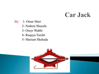
  • 1. By: 1- Omar Mari 2- Nathmi Shurafa 3- Omyr Wahbi 4- Ruqaya Turabi 5- Mariam Shehada
  • 2. A jack is mechanical device use to lift heavy loads or apply great forces. There are types of car Jack: 1-pneumatic or hydraulic. 2-mechanical hand. The most common form is a car jack ,floor jack or garage jack which lifts vehicles so that maintenance can be performed Conventionally a screw jack is used for : 1- lifting a vehicle to change a tire. 2-maintenance and many material handling operations.
  • 3. ๏ƒผ Paper, press, printing industry ๏ƒผ Gypsum factories ๏ƒผ Sheet metal forming machinery ๏ƒผ Mechanical lifting applications ๏ƒผ Platform lifting applications ๏ƒผ Food processing machinery ๏ƒผ Construction sector ๏ƒผ Bridge jacks for road and bridge lifting ๏ƒผ Shipyards ๏ƒผ Opening and closing of penstocks ๏ƒผ Industrial process ๏ƒผ Roll form machinery ๏ƒผ Mining industry ๏ƒผ Defence industry ๏ƒผ Lift tables ๏ƒผ Stage setup applications
  • 4. Hazards: In screw jack applications, the hazards are dropping, tipping or slipping of machines or their parts during the operation. The main reasons 1. Jack is overloaded 2. Load is improperly secured on the jack 3. Jack not placed on hard and level surface 4. Jack is used for a purpose for which it is not designed
  • 5. ๏ฝ 1-Platform and base: These members that make contact with ground and the service load. Base platform
  • 6. 2-power screw: The power screw is a single Acme threaded screw using to convert turning power to transmission power.
  • 7. 3- Joints(Trunion): Joints are used to link two beams with power screw.
  • 9. Rivet is used as fasteners and to link beam with base and platform 5-Rivets:
  • 10. 6-Handle: A cranck is used to turn the screw in the center of the jack
  • 11. ๏ฝ The force analysis consideration is based on the assumption that the screw jack is loaded vertically symmetrical and the weight on the screw jack equal 4000 N : 1-Member analysis: ๏ฝ ๐น๐‘‹ = 0 ๏ฝ F1 sin(๐œƒ) โ€“ F2 sin(๐œƒ)=0 F1 = F2 =F
  • 12. ๏ฝ ๐น๐‘Œ = 0 F1 cos(๐œƒ) + F2 cos(๐œƒ)=w F= ๐‘Š 2๐ถ๐‘‚๐‘†(๐œƒ) ๏ฝ ๐น๐‘Œ = 0 ๏ฝ F1 cos(๐œƒ) โ€“ F3 cos(๐œƒ)=0 F1 = F3 =F ๏ฝ ๐น๐‘‹ = 0 ๏ฝ F1 sin (๐œƒ) + F3sin(๐œƒ)= Fs FS = 2F*sin(๐œƒ)
  • 13. ๏ฝ At maximum raising height of the jack when h= 26.58 and ๐œƒ = 20ยฐ ๏ฝ F= ๐‘Š 2๐ถ๐‘‚๐‘†(๐œƒ) = 400 2๐ถ๐‘‚๐‘†(20) =2128.4 N ๏ฝ FS = 2F*sin (๐œƒ) = 2*212.84*sin (20)=1455.9 N Figure(a):shows position of the jack at maximum height.
  • 14. At minimum raising height of the jack when h= 9.58 and ๐œƒ = 70ยฐ F= ๐‘Š 2๐ถ๐‘‚๐‘†(๐œƒ) = 400 2๐ถ๐‘‚๐‘†(70) =5847.6 N FS = 2F*sin (๐œƒ) = 2*5847.6*sin (70)= 10990 N Since the maximum loading force will act at the minimum raising height of the jack, the design stresses will be analyzed at that point (h=9.58 m,๐œƒ = 70ยฐ ). Figure(b):shows position of the jack at minimum height
  • 15. ๏ฝ Shear in rivet: ๏ฝ Arivet = ฯ€/4 * d^2 = ฯ€/4 * (7.2)^2 = 40.72 mm2 ๏ฝ ๐œ= ๐‘… ๐ด = 2923.8 40.72 = 71.8 ๐‘€๐‘๐‘Ž ๏ฝ N= ๐‘†๐‘†๐‘ฆ ๐œ = 0.5โˆ—180 71.8 = 1.254 ๏ฝ Bearing in rivet: ๏ฝ Ab = d*thickness = 7.2*(4) =28.8 mm2 ๏ฝ ๐œŽ = ๐‘… ๐ด๐‘ = 2923.8 28.8 = 101.5๐‘€๐‘๐‘Ž ๏ฝ N = ๐‘†๐‘ฆ ๐œŽ = 180 101.5 = 1.77 2- Rivet analysis: Figure(c):show forces in load platform and its distribution in member and Revit.
  • 16. ๏ฝ Bearing in member : ๏ฝ Ab = d*thickness = 7.2*(4) =28.8 mm2 ๏ฝ ๐œŽ = ๐‘… ๐ด๐‘ = 2923.8 28.8 = 101.5๐‘€๐‘๐‘Ž ๏ฝ N = ๐‘†๐‘ฆ ๐œŽ = 180 101.5 = 1.77 ๏ฝ Rupture in member : member in compression ๏ฝ A = (10+10+35)*4= 220 mm2 ๏ฝ ๐œŽ = ๐น1 ๐ด = 5847.6 220 = 26.58 ๐‘€๐‘๐‘Ž ๏ฝ N = ๐‘†๐‘ฆ ๐œŽ = 180 26.58 = 6.7
  • 17. 3- ACME power screw analysis : ๏ฝ D = 13.5 mm ๏ฝ P = 3 mm ๏ฝ Dm = D - ๐‘ƒ 2 = 13.5 - 3 2 = 12 ๐‘š๐‘š ๏ฝ Nt = 107 thread ๏ฝ Dr = Dm - ๐‘ƒ 2 =12-1.5 =10.5 mm ๏ฝ ๐›ผ = 29ยฐ/2 = 14.5ยฐ ๏ฝ l=p=3mm ๏ฝ f = 0.2 ๏ฝ TR = ๐น๐‘ โˆ—๐ท๐‘š 2 *( ๐‘™+๐œ‹โˆ—๐‘“โˆ—๐ท๐‘šโˆ—sec(๐›ผ) ๐œ‹โˆ—๐ท๐‘šโˆ’๐‘“โˆ—๐‘™โˆ—sec(๐›ผ) ) = 10990โˆ—12 2 โˆ— ( 3+3.14โˆ—0.2โˆ—12โˆ—sec(14.5) 3.14โˆ—12โˆ’0.2โˆ—3โˆ—sec(14.5) )=19195.86 N.mm
  • 18. ๏ฝ To find the force acting by person in the end of the handle: ๏ฝ TR = Fh * 200 Fh = 19195.86/200 = 95.97 N ๏ฝ Stresses on the body of the power screw: ๏ฝ โ€ข Shear stress: ๏ฝ From force : ๏ฝ ๐‘ = ๐ท๐‘Ÿ/2=5.25 mm ๏ฝ ๐ฝ = ๐œ‹ 32 *๐ท๐‘Ÿ 4 = ๐œ‹ 32 *10.54 = 1192.71 mm4 ๏ฝ ๏ฝ ๐œ๐‘‡ = ๐‘‡๐‘…โˆ—๐‘ ๐ฝ = 19195.86โˆ—5.25 1192.71 = 84.5 Mpa ๏ฝ โ€ข Normal (axial compressive)stresses in ACME screw by Fs : ๏ฝ A = ฯ€/4* ๐ท๐‘Ÿ 2 = 3.14โˆ—(10.5)^2 4 = 86.54 mm2 ๏ฝ ๐œŽ = ๐น๐‘  ๐ด = 10990 86.54 = 127 ๐‘€๐‘๐‘Ž
  • 19. ๏ฝ Thread stresses in power screw : ๏ฝ โ€ข Nominal thread stress(bearing stress) in power screw ๏ฝ AB = ๐œ‹ โˆ— ๐‘‘๐‘š โˆ— ๐‘›๐‘ก โˆ— ๐‘/2 ๏ฝ ๐œŽB = ๐น๐‘  ๐ด๐ต = 2โˆ—๐น๐‘  ๐œ‹โˆ—๐‘‘๐‘šโˆ—๐‘›๐‘กโˆ—๐‘ = 10990โˆ—2 3.14โˆ—12โˆ—107โˆ—3 = 1.81 ๐‘€๐‘๐‘Ž ๏ฝ โ€ข The bending stress at the root of the thread is ๏ฝ M = ๐น๐‘  โˆ— ๐‘ 4 ๏ฝ R= ๐‘ 4 ๏ฝ I = ๐œ‹โˆ—๐‘‘๐‘Ÿโˆ—๐‘›๐‘ก โˆ—(๐‘/2)3 12 ๏ฝ ๐œŽb = ๐‘€โˆ—๐‘… ๐ผ = 6โˆ—๐น๐‘  ๐œ‹โˆ—๐‘‘๐‘Ÿโˆ—๐‘›๐‘กโˆ—๐‘ = 10990โˆ—6 3.14โˆ—10.5 โˆ—107โˆ—3 = 6.23 ๐‘€๐‘๐‘Ž Figure(d):show the force acting on the thread to determine stresses on it.
  • 20. ๏ฝ โ€ข The transverse shear stress at the center of the root of the thread ๏ฝ ๐œ = 3โˆ—๐น๐‘  ๐œ‹โˆ—๐‘‘๐‘Ÿโˆ—๐‘›๐‘กโˆ—๐‘ = 10990โˆ—3 3.14โˆ—10.5 โˆ—107โˆ—3 = 3.11 ๐‘€๐‘๐‘Ž ๏ฝ The root of the thread is a weakest point on the thread which there is three stresses act on it (axial compressive stress , shear stress due to torque and bending stress) ๏ฝ ๐œŽx = ๐œŽb = 6โˆ—๐น๐‘  ๐œ‹โˆ—๐‘‘๐‘Ÿโˆ—๐‘›๐‘กโˆ—๐‘ = 6.23 Mpa ๏ฝ ๐œ๐‘ฆ๐‘ง = ๐œ๐‘‡ = ๐‘‡๐‘…โˆ—๐‘ ๐ฝ = 19195.86โˆ—5.25 1192.71 = 84.5 Mpa ๏ฝ ๐œŽz= ๐œŽB = 4โˆ—๐น๐‘  ๐œ‹โˆ—๐‘‘๐‘Ÿ^2 = 127 Mpa ๏ฝ ๐œŽโ€ฒ = (๐œŽ๐‘ฅโˆ’๐œŽ๐‘ฆ)2+(๐œŽ๐‘ฆโˆ’๐œŽ๐‘ง)2+(๐œŽ๐‘งโˆ’๐œŽ๐‘ฅ)2+6(๐œ๐‘ง๐‘ฅ 2+๐œ๐‘ฆ๐‘ง 2+๐œ๐‘ฅ๐‘ฆ 2) 2 ๏ฝ ๐œŽโ€ฒ = (6.06)2+(โˆ’12.7)2+(12.7โˆ’6.06)2+6(8.452) 2 = 191.8 Mpa ๏ฝ ๐‘› = ๐‘†๐‘ฆ ๐œŽโ€ฒ = 300 191.8 = 1.56 Figure(e):show the stresses act in the root of the thread
  • 21. 4- Handle analysis : ๏ฝ Bending stress in the handle due to the force acted by a person (Fh = 95.97 N) ๏ฝ C = d/2 = 9.4/2 = 4.7 mm ๏ฝ I = ๐œ‹โˆ—๐‘‘4 64 = ๐œ‹โˆ—9.44 64 = 383 mm4 ๏ฝ M = Fh * 200 = 95.97 * 200 = 19194 N.mm ๏ฝ ๐œŽ = ๐‘€โˆ—๐ถ ๐ผ = 19194โˆ—4.7 383 = 235.5 ๐‘€๐‘๐‘Ž ๏ฝ N = ๐‘†๐‘ฆ ๐œŽ = 280 235.5 = 1.188 Figure12:show the force acting on the handle(Fh) by a person.
  • 22. ๏ฝ We studied car jack and determined the safety of each member through the appropriate calculations and practical considerations with reasonable assumptions . From our force and stress analysis it was discovered that the most sensitive position occur at the minimum height when theta = 70 so we made our analysis at that position using most allowable force (F=4000N) . ๏ฝ It worthy to mention that the jack was designed in minimal number of parts(Only rivet joints are induced Removal of welding to avoid distortion) that simplified assembly process and reduced its weight , but in the same time it can rise high load by applying very small force (we need force =96 N to rise 4000 N ).

Editor's Notes

  1. The following report describes the analysis of a simple screw jack. Conventionally a screw jack is used for lifting a vehicle to change a tire, to gain access to go to the underside of the vehicle, to lift the body to appreciable height, and many other applications also such lifts can be used for various purposes like maintenance and many material handling operations. It can be of mechanical, pneumatic or hydraulic type. The analysis described in the paper showed us that the jack can be operated by mechanical means so that the overall cost of the scissor jack is few in total. Finally the analysis is carried out in order to check the compatibility of the design values.
  2. Paper, press, printing industry Gypsum factories Sheet metal forming machinery Mechanical lifting applications Platform lifting applications Food processing machinery Construction sector Bridge jacks for road and bridge lifting Shipyards Opening and closing of penstocksย  Industrial process Roll form machinery Mining industry Defence industry Lift tables Stage setup applications
  3. In screw jack applications, the hazards are dropping, tipping or slipping of machines or their parts during the operation. The main reasons Jack is overloaded Load is improperly secured on the jack Jack not placed on hard and level surface Jack is used for a purpose for which it is not designed Proper size ,strength and stability are essential requirements for the design of the screw jack