SlideShare a Scribd company logo
1 of 8
Download to read offline
Application Report
SCEA044–June 2010
A Guide to Voltage Translation With TXS-Type Translators
Dave Moon, Aeysha Sultana ................................................................................... High Volume Linear
ABSTRACT
Modern trends are driving the need for lower supply voltages across many system-level designs. As most
processor voltage levels continue to decrease in the interest of achieving the lowest possible power
consumption, peripheral devices maintain a need for higher voltage levels, creating potential for voltage
discontinuities within a system. To remedy this mixed voltage system incompatibility, a voltage translator
can be used.
Texas Instruments High Volume Linear group offers a wide-range of voltage level translators. A variety of
architectures provide solutions for different application environments including dual-supply
direction-controlled, auto-direction sensing, and application-specific memory card interface translators.
The information in this application report is intended to help system designers understand the architecture
and operation of the TXS-type auto-direction sensing translator family
Contents
1 The Need For Voltage-Level Translation ................................................................................ 2
2 Auto-Direction Sensing Voltage Translator Architecture ............................................................... 2
3 Input Driver Requirements With TXS-Type Translators ............................................................... 6
4 Driving External Loads With TXS-Type Translators .................................................................... 7
5 Output Enable Control ...................................................................................................... 7
6 Conclusion ................................................................................................................... 7
List of Figures
1 Digital Switching Levels .................................................................................................... 2
2 Basic TXS0101, TXS0102, and TXS0104 Architecture................................................................ 3
3 Transfer Characterisitics of an N-Channel Transistor.................................................................. 3
4 Basic TXS0108E Architecture............................................................................................. 4
5 TXS0108E During Low-to-High Signal Transition ...................................................................... 5
6 TXS0108E During High-to-Low Signal Transition ...................................................................... 6
1SCEA044–June 2010 A Guide to Voltage Translation With TXS-Type Translators
Copyright © 2010, Texas Instruments Incorporated
VCC
VCC
VCC
VCC
VCC
VCC
VOH
VIH
VT
VIL
VOL
GND
5 V
4.44 V
0.7VCC
0.5VCC
0.3VCC
0.5 V
0 V
VIH
VIL
GND
VOH
VIH
VT
VIL VIL
VOL
GND
5 V
2.4 V
2 V
1.5 V
0.8 V
0.4 V
0 V
VOH
VIH
VT
VOL
GND
3.3 V
2.4 V
2 V
1.5 V
0.8 V
0.4 V
0 V
2.5 V
2.0 V
1.7 V
0.7 V
0.4 V
0 V
VOH
VIH
VIL
VOL
GND
1.8 V
VCC-0.45V
0.65VCC
0.35VCC
0.45 V
0 V
VOH
VIH
VIL
VOL
GND
1.2 V
0.65VCC
0.35VCC
0 V
VCC1.5 V
0.65VCC
0.35VCC
0 V
VIH
VIL
GND
5V CMOS 5V TTL 3.3V LVTTL 2.5V CMOS 1.8V CMOS 1.5V CMOS 1.2V CMOS
The Need For Voltage-Level Translation www.ti.com
1 The Need For Voltage-Level Translation
The need for voltage level translation is becoming increasingly significant in today's electronic systems. As
the digital switching level standards have continued to progress toward lower voltage levels, system
incompatibilities have arisen. Figure 1 illustrates the trend toward lower system voltage levels and
demonstrates the incompatibilities that mixed voltage systems can face.
Figure 1. Digital Switching Levels
For two devices to interface reliably, the output driver voltages must be compatible with receiver input
thresholds. For this condition to be met in mixed voltage systems, a voltage translator is often required.
Texas Instruments offers several unique device architectures for addressing voltage translation needs.
The most familiar to system designers is probably a direction-controlled buffer translator, such as the
SN74AVC8T245. These translators can help remedy many problems in system voltage compatibility but
require DIR (direction) control pins. If the system environment does not provide a programmable GPIO to
control the direction pin, an auto-direction sensing translator architecture can provide an alternative
translation solution.
2 Auto-Direction Sensing Voltage Translator Architecture
If a processer GPIO input direction-control signal is not available or if one is not desired, an auto-direction
sensing voltage translator can provide a robust solution. As the name implies, this type of translator does
not require the use of a direction control signal, and each channel supports independent transmission or
reception of data. This eliminates the need for a processor GPIO to control a DIR input, resulting in
simplified software driver development as well as smaller device packaging due to reduced pin count.
The two types of auto-direction sensing voltage translator architectures are TXB buffered-type and TXS
switch-type. Neither type of architecture requires a DIR control signal to establish the direction of data
flow. The TXB translators are designed to exclusively be connected and interfaced with a push-pull drivers
and are capable of driving a light capacitive or high impedance loads in applications such as Secure
Digital (SD) or Serial Peripheral Interface (SPI). See the TI application report, A Guide to Voltage
Translation With TXB-Type Translators (SCEA043) for more information on the TXB-type voltage
translators.
Texas Instruments has developed several types of TXS-type (where the "S" indicates switch-type)
translators that are designed to interface with open-drain drivers and can be used in applications such as
I2
C.
2 A Guide to Voltage Translation With TXS-Type Translators SCEA044–June 2010
Copyright © 2010, Texas Instruments Incorporated
B
Gate Bias
One
shot
T2T1
VCCA VCCB
A
Gate Bias
N2
One-
shot
R1
10k
R2
10k
One
shot
One-
shot
V (V)IN
V = 4.3 VGATE
V = 3.5 VGATE
V = 2.8 VGATE
V = 2.5 VGATE
V = 2.2 VGATE
V(V)OUT
www.ti.com Auto-Direction Sensing Voltage Translator Architecture
2.1 Initial Series of TXS Type Devices
The initial series of TXS type devices are the TXS0101, TXS0102, and TXS0104E. The basic block
diagram architecture of a single-bit (or channel) is shown in Figure 2.
Figure 2. Basic TXS0101, TXS0102, and TXS0104 Architecture
These TXS translators are FET-based architectures that utilize an N-channel pass-gate transistor to open
and close the connection between the A-port and B-port. When a driver connected to A or B port is low,
the opposite port is, in turn, pulled low by the N2 pass-gate transistor. This pass-transistor type voltage
translator is ideal for down-translation and over-voltage protection.
Figure 3 shows the transfer characteristics of the N2 pass-gate transistor, where the threshold voltage (VT)
is approximately 1 V and the gate bias voltage (VGATE) is as shown.
Figure 3. Transfer Characterisitics of an N-Channel Transistor
The pass-gate transistor, N2, is on when VGS > VT. Consider first the case where one side of N2 is held
low by an external driver. With the input to N2 at 0V, N2 will be “On” and the output of N2 will be held to
nearly 0V due to the on-state resistance of N2. As can be seen in Figure 3, as the input voltage rises due
to a rising edge, the output voltage of N2 will track the input until of N2 turns off at VGATE – VT. After N2
stops conducting, the input and output ports will continue to rise to their respective supply voltages due to
3SCEA044–June 2010 A Guide to Voltage Translation With TXS-Type Translators
Copyright © 2010, Texas Instruments Incorporated
VCCA
A
VCCB
One-Shot
One-ShotN1
P1
R1 R2
Translator
One-Shot
One-Shot N2
OS1
OS2
OS4
OS3
T2
T1
RpubRpua
Bias
Npass
B
P2
Translator
Auto-Direction Sensing Voltage Translator Architecture www.ti.com
the internal pull-up resistors on either port. Secondly, consider the case where both ports start out high.
The ports will be held at static high levels due to the internal pull-up resistors. When the input port is
pulled low by an external driver, N2 will begin to conduct once VGS > VT. As N2 starts to conduct the
output will begin to track the input port following the curve in the Figure 3. The sinking-current required to
perform this translation function must be provided by an external system driver that is connected to either
the A or B ports.
These pass-transistor voltage translators and their voltage clamping feature makes TXS type translators
an ideal choice for applications requiring over-voltage protection and addition to voltage level translation.
The signal propagation delay through the N2 transistor is extremely fast making it an elegant solution.
To achieve faster data rates through the device, these translators include rising edge-rate acceleration
circuitry to provide stronger ac-drive by bypassing these integrated 10-kΩ pull-up resistors through a low
impedance path during low-to-high signal transitions. A one-shot (O.S.) circuit with an associated T1/T2
PMOS transistors is used to increase switching speeds for the rising-edge input signals. When a rising
edge is detected by the O.S. circuit, the T1/T2 PMOS transistors turn on momentarily to rapidly drive the
port high, effectively lowering the output impedance seen on that port and speeding up rising edge inputs.
The combination of an N-channel pass FET, integrated 10-kΩ pull-up resistors, and edge-rate acceleration
circuits makes the TXS type translators ideal for interfacing devices or systems operating at disparate
voltage levels while also allowing for simple interfacing with open-drain (O.D.) as is required in I2
C, 1-wire,
and MMC-card interface applications.
The TXS0101, TXS0102, and TXS0104E translators also incorporate integrated pull-up resistors and
higher level ESD protection which saves board space and overall BOM cost. TXS-type translators can
support push-pull driving applications, and have the ability to drive slightly heavier Impedance loads than
the TXB-type translators. However, the TXB-type translators may prove to be a better solution if the
capacitive loading is <70pF.
2.2 Second Series of TXS Type Devices
The second series switch-type translator is the TXS0108E semi-buffered type architecture and is targeted
for higher speed applications. The basic block diagram of a single-bit (or channel) of this "semi-buffered"
translator is shown in Figure 4.
Figure 4. Basic TXS0108E Architecture
4 A Guide to Voltage Translation With TXS-Type Translators SCEA044–June 2010
Copyright © 2010, Texas Instruments Incorporated
One-
Shot
Translator
1.8V
Time – ns
3.3V
Input
signal
Output
signal
V = 1.8 V and V = 3.3 VCCA CCB
www.ti.com Auto-Direction Sensing Voltage Translator Architecture
The design goals for this type of translator were to achieve faster data rates while also providing support
for applications where a channel needs to start out in a low-speed open-drain (O.D.) mode, but eventually
transition over to a higher-speed push-pull mode. MMC memory card applications are an example of this
type of operating mode. The TXS0108E translator reliably supports high-speed data rates in excess of 60
Mbps, whereas the initial TXS series type translators supported slightly less than half this. The ability to
translate down to the 1.2V operating-node is also supported in the TXS0108E device.
To achieve these faster data rates, both rising-edge and falling-edge rate acceleration circuitry is
incorporated for symmetrical ac-drive. Again, these accelerators bypass the integrated pull-up resistors
during low-to-high and high-to-low signal transitions and speed up the output slew rate after monitoring A
and B port input rising and falling edges for signal transitions. Figure 4 shows the O.S. circuit and its
associated P1/P2 PMOS transistor which are used to improve switching speeds for the rising edge signal
by lowering the output impedance seen on that port and speeding up the rising edge rate.
Figure 5 shows a low-to-high transition.
Figure 5. TXS0108E During Low-to-High Signal Transition
The translator’s T1, OS3 and P2 element paths are activated when a low-to-high signal is applied at the A
port. The OS3 edge-rate accelerator facilitates the fast ramping of low-to-high transition of the signal at the
output. The pull-up resistors Rpua and Rpub provide dc-bias to hold the opposite port high when one of the
ports is being driven high. During this acceleration phase, the output resistance of the driver is decreased
to approximately 50 Ω - 70 Ω to increase the current drive capability of the device.
Figure 6 shows a high-to-low transition:
5SCEA044–June 2010 A Guide to Voltage Translation With TXS-Type Translators
Copyright © 2010, Texas Instruments Incorporated
One-
Shot
Translator
V = 1.8 V and V = 3.3 VCCA CCB
1.8V
3.3V
Input
signal
Output
signal
Time – ns
Input Driver Requirements With TXS-Type Translators www.ti.com
Figure 6. TXS0108E During High-to-Low Signal Transition
The translator’s T1, OS4 and N2 element paths are activated when a high-to-low signal is applied at the A
port. The OS4 edge-rate accelerator facilitates the fast ramping of high-to-low transition of the signal at the
output. The N-channel pass-gate transistor and resistors R1 and R2 provide a dc path between ports A
and B. They also provide dc-bias to hold the opposite port low when one of the ports is driven low.
The TXS0101/2/4 translators have fixed 10-kΩ value pull-up resistors which provide dc-bias and dc
current sourcing/drive capabilities to maintain a high. A key feature that was included in the TXS0108E
translator to allow it to operate better in SDIO applications is the use of "smart" pull-up resistors. This
feature provides lower static power consumption (when the I/Os are passing a low), supports lower VOL
values for the same size pass-gate transistor, and helps improve simultaneous switching performance.
These smart pull-up resistors dynamically change value based on whether a low or a high is being passed
through the I/O line, as follows:
• RPUa and RPUb values are 4 kΩ when the output is driving a high.
• RPUa and RPUb values are 40 kΩ when the output is driving a low.
• The I/O goes into High-Z when the device is disabled via the OE pin or by pulling the either VCCA or
VCCB to 0 V.
The series resistance values of R1 and R2 are 150 Ω (typical). The VGATE gate bias voltage of the
N-channel pass transistor is again set to a level that optimizes the switch characteristics for maximum
data rate as well as minimal static supply leakage.
3 Input Driver Requirements With TXS-Type Translators
The continuous dc-current "sinking" capability is determined by the external system-level driver interfaced
to the TXS-type translator. For high bandwidth bidirectional SDIO circuit applications, the I/O port needs to
quickly change from an input to an output and vice-vera. Therefore, a modest dc-current "sourcing"
capability of 100 to 200 micro-Amps is needed and the smart pullup resistor values determine the sinking
capability. The fall time (tfA, tfB) of a signal depends on the edge rate and output impedance of the external
device driving these SDIO lines as well as the capacitive loading on these lines. Similarly, the tpd and max
data rates also depend on the output impedance of the external driver. The values for tfA, tfB, tpd, and
maximum data rates specified in the TXS data sheets assume that the output impedance of the external
driver is less than 50 Ω.
6 A Guide to Voltage Translation With TXS-Type Translators SCEA044–June 2010
Copyright © 2010, Texas Instruments Incorporated
www.ti.com Driving External Loads With TXS-Type Translators
4 Driving External Loads With TXS-Type Translators
The TXS-type translators were architected for driving high-impedance loads. As such, the O.S. duration
has been set to best optimize trade-offs between dynamic current consumption (ICC), load driving
capability, and maximum bit-rate considerations. Careful Printed-Circuit-Board (PCB) layout practices with
short trace lengths should be followed to avoid excessive capacitive loading. Ensuring proper O.S.
triggering will avoid bus contention, output signal oscillations, and other adverse system-level affects. To
accomplish this, PCB signal trace-lengths should be kept short enough such that the round trip delay of
any reflection is less than the one-shot duration. This improves signal integrity by ensuring that any
reflection sees a low impedance at the source driver. The O.S. circuits have been designed to stay on for
10 to 30 ns so the maximum capacitance of the lumped load that can be driven also depends reliably also
depends directly on this one-shot duration.
There is a tradeoff between achieving a maximum data rate and driving heavy capacitive loads
simultaneously. With heavy capacitive loads, the one-shot can time-out before the signal is driven fully to
the positive rail. In this scenario, only the pull-up resistors will pull the line high in accordance with its RC
time-constant determined by the resistive and capacitive loadings. It is best to avoid this condition by
driving capacitive loads less than 70pF when maximum data rate are desired. With capacitive loading
>70pF, the TXS-type devices will still successfully operate at lower data rates.
If the application requires an external pullup or pulldown resistor (Rpu or Rpd) special consideration must be
given to the resistor value. It is important to choose a large enough Rpu or Rpd to ensure adequate VOH and
VOL levels at the output port of the translator.
To minimize dynamic ICC and the possibility of signal contention, the user should wait for the O.S. circuit to
turn-off before applying a signal in the opposite direction. The worst-case duration is equal to the minimum
pulse-width number provided in the Timing Requirements section of this data sheet. Once the O.S. is
triggered and switched off, both the A and B ports must go to the same state (i.e. both high or both low)
for the one-shot to trigger again. In a dc state, the output drivers maintain a low state through the pass
transistor.
5 Output Enable Control
The TXS devices offer low power consumption of 5 to 10 µA maximum ICC when the output enable is high.
When the output enable is low, the TXS translator buffer is disabled and the outputs are placed intohigh
impedance state for increased power savings. The OE input circuit is referenced to the VCCA power supply
and when the device is disabled, the pullup resistors are disabled. In addition, current leakage on the A or
B ports will be less than ±1 mA when the outputs are disabled. If the application does not require output
enable control then the OE pin should be tied to the VCCA supply. Leaving OE floating in an indeterminate
state can cause undesirable quiescent current to flow in the device which subsequently increases the
overall power dissipation of the device.
The outputs are also disabled and put into a high-impedance state under partial power down conditions
and this feature is referred to as a VCC isolation feature. If VCCB = 0 V, the A-port is disabled. Likewise, if
VCCA = 0 V, the B-port is disabled. For the TXS type translators that do not have IEC level ESD protection
(i.e. ±15-kV Air-Gap and ±8-kV Contact discharge), they are fully specified for partial-power-down
applications using the IOFF feature. This IOFF circuitry disables the outputs, preventing damaging current
backflow through the device when these devices are powered down.
6 Conclusion
The TXS translators offer system designers a good solution to remedy mixed-voltage system
incompatibilities when interfacing with open-drain drivers in applications such as I2
C. These translators
eliminate the need for provisioning a GPIO of a processor, since they change the direction of the data flow
automatically without the use of a direction control pin. This can simplify software driver development and
allows for solutions in smaller packages because of this direction control pin savings.
Visit www.ti.com for data sheets for all bit-width TXS translators along with the full line of Texas
Instruments voltage translators.
7SCEA044–June 2010 A Guide to Voltage Translation With TXS-Type Translators
Copyright © 2010, Texas Instruments Incorporated
IMPORTANT NOTICE
Texas Instruments Incorporated and its subsidiaries (TI) reserve the right to make corrections, modifications, enhancements, improvements,
and other changes to its products and services at any time and to discontinue any product or service without notice. Customers should
obtain the latest relevant information before placing orders and should verify that such information is current and complete. All products are
sold subject to TI’s terms and conditions of sale supplied at the time of order acknowledgment.
TI warrants performance of its hardware products to the specifications applicable at the time of sale in accordance with TI’s standard
warranty. Testing and other quality control techniques are used to the extent TI deems necessary to support this warranty. Except where
mandated by government requirements, testing of all parameters of each product is not necessarily performed.
TI assumes no liability for applications assistance or customer product design. Customers are responsible for their products and
applications using TI components. To minimize the risks associated with customer products and applications, customers should provide
adequate design and operating safeguards.
TI does not warrant or represent that any license, either express or implied, is granted under any TI patent right, copyright, mask work right,
or other TI intellectual property right relating to any combination, machine, or process in which TI products or services are used. Information
published by TI regarding third-party products or services does not constitute a license from TI to use such products or services or a
warranty or endorsement thereof. Use of such information may require a license from a third party under the patents or other intellectual
property of the third party, or a license from TI under the patents or other intellectual property of TI.
Reproduction of TI information in TI data books or data sheets is permissible only if reproduction is without alteration and is accompanied
by all associated warranties, conditions, limitations, and notices. Reproduction of this information with alteration is an unfair and deceptive
business practice. TI is not responsible or liable for such altered documentation. Information of third parties may be subject to additional
restrictions.
Resale of TI products or services with statements different from or beyond the parameters stated by TI for that product or service voids all
express and any implied warranties for the associated TI product or service and is an unfair and deceptive business practice. TI is not
responsible or liable for any such statements.
TI products are not authorized for use in safety-critical applications (such as life support) where a failure of the TI product would reasonably
be expected to cause severe personal injury or death, unless officers of the parties have executed an agreement specifically governing
such use. Buyers represent that they have all necessary expertise in the safety and regulatory ramifications of their applications, and
acknowledge and agree that they are solely responsible for all legal, regulatory and safety-related requirements concerning their products
and any use of TI products in such safety-critical applications, notwithstanding any applications-related information or support that may be
provided by TI. Further, Buyers must fully indemnify TI and its representatives against any damages arising out of the use of TI products in
such safety-critical applications.
TI products are neither designed nor intended for use in military/aerospace applications or environments unless the TI products are
specifically designated by TI as military-grade or "enhanced plastic." Only products designated by TI as military-grade meet military
specifications. Buyers acknowledge and agree that any such use of TI products which TI has not designated as military-grade is solely at
the Buyer's risk, and that they are solely responsible for compliance with all legal and regulatory requirements in connection with such use.
TI products are neither designed nor intended for use in automotive applications or environments unless the specific TI products are
designated by TI as compliant with ISO/TS 16949 requirements. Buyers acknowledge and agree that, if they use any non-designated
products in automotive applications, TI will not be responsible for any failure to meet such requirements.
Following are URLs where you can obtain information on other Texas Instruments products and application solutions:
Products Applications
Amplifiers amplifier.ti.com Audio www.ti.com/audio
Data Converters dataconverter.ti.com Automotive www.ti.com/automotive
DLP® Products www.dlp.com Communications and www.ti.com/communications
Telecom
DSP dsp.ti.com Computers and www.ti.com/computers
Peripherals
Clocks and Timers www.ti.com/clocks Consumer Electronics www.ti.com/consumer-apps
Interface interface.ti.com Energy www.ti.com/energy
Logic logic.ti.com Industrial www.ti.com/industrial
Power Mgmt power.ti.com Medical www.ti.com/medical
Microcontrollers microcontroller.ti.com Security www.ti.com/security
RFID www.ti-rfid.com Space, Avionics & www.ti.com/space-avionics-defense
Defense
RF/IF and ZigBee® Solutions www.ti.com/lprf Video and Imaging www.ti.com/video
Wireless www.ti.com/wireless-apps
Mailing Address: Texas Instruments, Post Office Box 655303, Dallas, Texas 75265
Copyright © 2010, Texas Instruments Incorporated

More Related Content

What's hot

Self powered door-bell watcher
Self powered door-bell watcherSelf powered door-bell watcher
Self powered door-bell watcherabdullahkhalid50
 
automation of waterpump using 8051 microcontroller
automation of waterpump using 8051 microcontrollerautomation of waterpump using 8051 microcontroller
automation of waterpump using 8051 microcontrollerParth Joshi
 
Introduction to Thyristor Power Controllers
Introduction to Thyristor Power ControllersIntroduction to Thyristor Power Controllers
Introduction to Thyristor Power ControllersWest Control Solutions
 
Voltage to-frequency and frequency-to-voltage converter
Voltage to-frequency and frequency-to-voltage converterVoltage to-frequency and frequency-to-voltage converter
Voltage to-frequency and frequency-to-voltage converterThe Hoa Nguyen
 
direct coupled transistor logic
direct coupled transistor logicdirect coupled transistor logic
direct coupled transistor logicsonalijagtap15
 
1 mrg000577 en_application_of_unit_protection_schemes_for_auto-transformers1
1 mrg000577 en_application_of_unit_protection_schemes_for_auto-transformers11 mrg000577 en_application_of_unit_protection_schemes_for_auto-transformers1
1 mrg000577 en_application_of_unit_protection_schemes_for_auto-transformers1NASSAR KALLIKETTIYAPURAKAL
 
3 phase appliance protector
3 phase appliance protector3 phase appliance protector
3 phase appliance protectorviv3ksharma
 
Review of Step down Converter with Efficient ZVS Operation
Review of Step down Converter with Efficient ZVS OperationReview of Step down Converter with Efficient ZVS Operation
Review of Step down Converter with Efficient ZVS OperationIJRST Journal
 
Frequency to voltage converter.final
Frequency to voltage converter.finalFrequency to voltage converter.final
Frequency to voltage converter.finalprashant singh
 
Distance Protection
Distance ProtectionDistance Protection
Distance Protectionncct
 
Hybrid Analog-Digital Architecture for Massive MIMO: An Introduction
Hybrid Analog-Digital Architecture for Massive MIMO: An IntroductionHybrid Analog-Digital Architecture for Massive MIMO: An Introduction
Hybrid Analog-Digital Architecture for Massive MIMO: An IntroductionT. E. BOGALE
 
Modular Multilevel Inverter
Modular Multilevel InverterModular Multilevel Inverter
Modular Multilevel InverterAjay Kumar
 
Simulation of sinosoidal pulse width modulation
Simulation of sinosoidal pulse width modulationSimulation of sinosoidal pulse width modulation
Simulation of sinosoidal pulse width modulationTanzeel Ahmad
 
LT3755 - High Side Sense LED Controller for High Current LED Applications
LT3755 - High Side Sense LED Controller for  High Current LED ApplicationsLT3755 - High Side Sense LED Controller for  High Current LED Applications
LT3755 - High Side Sense LED Controller for High Current LED ApplicationsPremier Farnell
 

What's hot (19)

Self powered door-bell watcher
Self powered door-bell watcherSelf powered door-bell watcher
Self powered door-bell watcher
 
automation of waterpump using 8051 microcontroller
automation of waterpump using 8051 microcontrollerautomation of waterpump using 8051 microcontroller
automation of waterpump using 8051 microcontroller
 
Mcp2551
Mcp2551Mcp2551
Mcp2551
 
Introduction to Thyristor Power Controllers
Introduction to Thyristor Power ControllersIntroduction to Thyristor Power Controllers
Introduction to Thyristor Power Controllers
 
Voltage to-frequency and frequency-to-voltage converter
Voltage to-frequency and frequency-to-voltage converterVoltage to-frequency and frequency-to-voltage converter
Voltage to-frequency and frequency-to-voltage converter
 
direct coupled transistor logic
direct coupled transistor logicdirect coupled transistor logic
direct coupled transistor logic
 
1 mrg000577 en_application_of_unit_protection_schemes_for_auto-transformers1
1 mrg000577 en_application_of_unit_protection_schemes_for_auto-transformers11 mrg000577 en_application_of_unit_protection_schemes_for_auto-transformers1
1 mrg000577 en_application_of_unit_protection_schemes_for_auto-transformers1
 
70155TechnicalBrief
70155TechnicalBrief70155TechnicalBrief
70155TechnicalBrief
 
C1103022832
C1103022832C1103022832
C1103022832
 
3 phase appliance protector
3 phase appliance protector3 phase appliance protector
3 phase appliance protector
 
Naladharmakavaskar.s
Naladharmakavaskar.sNaladharmakavaskar.s
Naladharmakavaskar.s
 
Review of Step down Converter with Efficient ZVS Operation
Review of Step down Converter with Efficient ZVS OperationReview of Step down Converter with Efficient ZVS Operation
Review of Step down Converter with Efficient ZVS Operation
 
Frequency to voltage converter.final
Frequency to voltage converter.finalFrequency to voltage converter.final
Frequency to voltage converter.final
 
Distance Protection
Distance ProtectionDistance Protection
Distance Protection
 
Hybrid Analog-Digital Architecture for Massive MIMO: An Introduction
Hybrid Analog-Digital Architecture for Massive MIMO: An IntroductionHybrid Analog-Digital Architecture for Massive MIMO: An Introduction
Hybrid Analog-Digital Architecture for Massive MIMO: An Introduction
 
Datasheet
DatasheetDatasheet
Datasheet
 
Modular Multilevel Inverter
Modular Multilevel InverterModular Multilevel Inverter
Modular Multilevel Inverter
 
Simulation of sinosoidal pulse width modulation
Simulation of sinosoidal pulse width modulationSimulation of sinosoidal pulse width modulation
Simulation of sinosoidal pulse width modulation
 
LT3755 - High Side Sense LED Controller for High Current LED Applications
LT3755 - High Side Sense LED Controller for  High Current LED ApplicationsLT3755 - High Side Sense LED Controller for  High Current LED Applications
LT3755 - High Side Sense LED Controller for High Current LED Applications
 

Viewers also liked

Viewers also liked (8)

Resume - Shantanu Bhate
Resume - Shantanu BhateResume - Shantanu Bhate
Resume - Shantanu Bhate
 
maniresume1
maniresume1maniresume1
maniresume1
 
1 s2.0-s0887899413001999-main
1 s2.0-s0887899413001999-main1 s2.0-s0887899413001999-main
1 s2.0-s0887899413001999-main
 
Cv updated
Cv updated Cv updated
Cv updated
 
review-1
review-1review-1
review-1
 
Soundhari_CV_Oct'15
Soundhari_CV_Oct'15Soundhari_CV_Oct'15
Soundhari_CV_Oct'15
 
Shyam Kumar Vishwakarma
Shyam Kumar VishwakarmaShyam Kumar Vishwakarma
Shyam Kumar Vishwakarma
 
Sindhura Vallabhaneni
Sindhura VallabhaneniSindhura Vallabhaneni
Sindhura Vallabhaneni
 

Similar to translator

A DAPTIVE S UPPLY V OLTAGE M ANAGEMENT F OR L OW P OWER L OGIC C IRCU...
A DAPTIVE  S UPPLY  V OLTAGE  M ANAGEMENT  F OR  L OW  P OWER  L OGIC  C IRCU...A DAPTIVE  S UPPLY  V OLTAGE  M ANAGEMENT  F OR  L OW  P OWER  L OGIC  C IRCU...
A DAPTIVE S UPPLY V OLTAGE M ANAGEMENT F OR L OW P OWER L OGIC C IRCU...VLSICS Design
 
Study and implementation of comparator in cmos 50 nm technology
Study and implementation of comparator in cmos 50 nm technologyStudy and implementation of comparator in cmos 50 nm technology
Study and implementation of comparator in cmos 50 nm technologyeSAT Journals
 
Study and implementation of comparator in cmos 50 nm
Study and implementation of comparator in cmos 50 nmStudy and implementation of comparator in cmos 50 nm
Study and implementation of comparator in cmos 50 nmeSAT Publishing House
 
Low Power Design Techniques for ASIC / SOC Design
Low Power Design Techniques for ASIC / SOC DesignLow Power Design Techniques for ASIC / SOC Design
Low Power Design Techniques for ASIC / SOC DesignRajesh_navandar
 
IRJET - A Zero Voltage Switching Pulse Width Modulated Multilevel Buck Converter
IRJET - A Zero Voltage Switching Pulse Width Modulated Multilevel Buck ConverterIRJET - A Zero Voltage Switching Pulse Width Modulated Multilevel Buck Converter
IRJET - A Zero Voltage Switching Pulse Width Modulated Multilevel Buck ConverterIRJET Journal
 
AUTOMATIC GRID ON SENSING BAD VOLTAGE OR FREQUENCY
AUTOMATIC GRID ON SENSING BAD VOLTAGE OR FREQUENCYAUTOMATIC GRID ON SENSING BAD VOLTAGE OR FREQUENCY
AUTOMATIC GRID ON SENSING BAD VOLTAGE OR FREQUENCYGaurav Singh
 
File 1389427052
File 1389427052File 1389427052
File 1389427052Aman_preet
 
09 15 dec13 #5019 harmonic mitigeted front end
09 15 dec13 #5019 harmonic mitigeted front end09 15 dec13 #5019 harmonic mitigeted front end
09 15 dec13 #5019 harmonic mitigeted front endIJPEDS-IAES
 
Design of Low Power & High Speed Comparator with 0.18μm Technology for ADC Ap...
Design of Low Power & High Speed Comparator with 0.18μm Technology for ADC Ap...Design of Low Power & High Speed Comparator with 0.18μm Technology for ADC Ap...
Design of Low Power & High Speed Comparator with 0.18μm Technology for ADC Ap...IJERA Editor
 
Flexible AC Transmitter by using TSR.pptx
Flexible AC Transmitter by using TSR.pptxFlexible AC Transmitter by using TSR.pptx
Flexible AC Transmitter by using TSR.pptxAmeerHamza842286
 
New zv zcs full bridge dc-dc converter with fuzzy & pi control
New zv zcs full bridge dc-dc converter with fuzzy & pi controlNew zv zcs full bridge dc-dc converter with fuzzy & pi control
New zv zcs full bridge dc-dc converter with fuzzy & pi controlIAEME Publication
 
Design and Analysis of Low Power Double Tail Comparator for 2-bit Fast ADC
Design and Analysis of Low Power Double Tail Comparator for 2-bit Fast ADCDesign and Analysis of Low Power Double Tail Comparator for 2-bit Fast ADC
Design and Analysis of Low Power Double Tail Comparator for 2-bit Fast ADCIJCSIS Research Publications
 
Unit iv microcontrollers final
Unit iv microcontrollers finalUnit iv microcontrollers final
Unit iv microcontrollers finalSARITHA REDDY
 
Application of SVM Technique for Three Phase Three Leg Ac/Ac Converter Topology
Application of SVM Technique for Three Phase Three Leg Ac/Ac Converter TopologyApplication of SVM Technique for Three Phase Three Leg Ac/Ac Converter Topology
Application of SVM Technique for Three Phase Three Leg Ac/Ac Converter TopologyIOSR Journals
 

Similar to translator (20)

A DAPTIVE S UPPLY V OLTAGE M ANAGEMENT F OR L OW P OWER L OGIC C IRCU...
A DAPTIVE  S UPPLY  V OLTAGE  M ANAGEMENT  F OR  L OW  P OWER  L OGIC  C IRCU...A DAPTIVE  S UPPLY  V OLTAGE  M ANAGEMENT  F OR  L OW  P OWER  L OGIC  C IRCU...
A DAPTIVE S UPPLY V OLTAGE M ANAGEMENT F OR L OW P OWER L OGIC C IRCU...
 
Jh2416211626
Jh2416211626Jh2416211626
Jh2416211626
 
Study and implementation of comparator in cmos 50 nm technology
Study and implementation of comparator in cmos 50 nm technologyStudy and implementation of comparator in cmos 50 nm technology
Study and implementation of comparator in cmos 50 nm technology
 
Study and implementation of comparator in cmos 50 nm
Study and implementation of comparator in cmos 50 nmStudy and implementation of comparator in cmos 50 nm
Study and implementation of comparator in cmos 50 nm
 
A320108
A320108A320108
A320108
 
Low Power Design Techniques for ASIC / SOC Design
Low Power Design Techniques for ASIC / SOC DesignLow Power Design Techniques for ASIC / SOC Design
Low Power Design Techniques for ASIC / SOC Design
 
IRJET - A Zero Voltage Switching Pulse Width Modulated Multilevel Buck Converter
IRJET - A Zero Voltage Switching Pulse Width Modulated Multilevel Buck ConverterIRJET - A Zero Voltage Switching Pulse Width Modulated Multilevel Buck Converter
IRJET - A Zero Voltage Switching Pulse Width Modulated Multilevel Buck Converter
 
AUTOMATIC GRID ON SENSING BAD VOLTAGE OR FREQUENCY
AUTOMATIC GRID ON SENSING BAD VOLTAGE OR FREQUENCYAUTOMATIC GRID ON SENSING BAD VOLTAGE OR FREQUENCY
AUTOMATIC GRID ON SENSING BAD VOLTAGE OR FREQUENCY
 
File 1389427052
File 1389427052File 1389427052
File 1389427052
 
Npc informe final
Npc informe finalNpc informe final
Npc informe final
 
09 15 dec13 #5019 harmonic mitigeted front end
09 15 dec13 #5019 harmonic mitigeted front end09 15 dec13 #5019 harmonic mitigeted front end
09 15 dec13 #5019 harmonic mitigeted front end
 
[IJET-V1I6P3] Authors:Bachwad M.R. , Maske Ashadeep M
[IJET-V1I6P3] Authors:Bachwad M.R. , Maske Ashadeep M[IJET-V1I6P3] Authors:Bachwad M.R. , Maske Ashadeep M
[IJET-V1I6P3] Authors:Bachwad M.R. , Maske Ashadeep M
 
Design of Low Power & High Speed Comparator with 0.18μm Technology for ADC Ap...
Design of Low Power & High Speed Comparator with 0.18μm Technology for ADC Ap...Design of Low Power & High Speed Comparator with 0.18μm Technology for ADC Ap...
Design of Low Power & High Speed Comparator with 0.18μm Technology for ADC Ap...
 
Flexible AC Transmitter by using TSR.pptx
Flexible AC Transmitter by using TSR.pptxFlexible AC Transmitter by using TSR.pptx
Flexible AC Transmitter by using TSR.pptx
 
Lica 7th chapter slides
Lica 7th chapter slidesLica 7th chapter slides
Lica 7th chapter slides
 
New zv zcs full bridge dc-dc converter with fuzzy & pi control
New zv zcs full bridge dc-dc converter with fuzzy & pi controlNew zv zcs full bridge dc-dc converter with fuzzy & pi control
New zv zcs full bridge dc-dc converter with fuzzy & pi control
 
Cz36611614
Cz36611614Cz36611614
Cz36611614
 
Design and Analysis of Low Power Double Tail Comparator for 2-bit Fast ADC
Design and Analysis of Low Power Double Tail Comparator for 2-bit Fast ADCDesign and Analysis of Low Power Double Tail Comparator for 2-bit Fast ADC
Design and Analysis of Low Power Double Tail Comparator for 2-bit Fast ADC
 
Unit iv microcontrollers final
Unit iv microcontrollers finalUnit iv microcontrollers final
Unit iv microcontrollers final
 
Application of SVM Technique for Three Phase Three Leg Ac/Ac Converter Topology
Application of SVM Technique for Three Phase Three Leg Ac/Ac Converter TopologyApplication of SVM Technique for Three Phase Three Leg Ac/Ac Converter Topology
Application of SVM Technique for Three Phase Three Leg Ac/Ac Converter Topology
 

translator

  • 1. Application Report SCEA044–June 2010 A Guide to Voltage Translation With TXS-Type Translators Dave Moon, Aeysha Sultana ................................................................................... High Volume Linear ABSTRACT Modern trends are driving the need for lower supply voltages across many system-level designs. As most processor voltage levels continue to decrease in the interest of achieving the lowest possible power consumption, peripheral devices maintain a need for higher voltage levels, creating potential for voltage discontinuities within a system. To remedy this mixed voltage system incompatibility, a voltage translator can be used. Texas Instruments High Volume Linear group offers a wide-range of voltage level translators. A variety of architectures provide solutions for different application environments including dual-supply direction-controlled, auto-direction sensing, and application-specific memory card interface translators. The information in this application report is intended to help system designers understand the architecture and operation of the TXS-type auto-direction sensing translator family Contents 1 The Need For Voltage-Level Translation ................................................................................ 2 2 Auto-Direction Sensing Voltage Translator Architecture ............................................................... 2 3 Input Driver Requirements With TXS-Type Translators ............................................................... 6 4 Driving External Loads With TXS-Type Translators .................................................................... 7 5 Output Enable Control ...................................................................................................... 7 6 Conclusion ................................................................................................................... 7 List of Figures 1 Digital Switching Levels .................................................................................................... 2 2 Basic TXS0101, TXS0102, and TXS0104 Architecture................................................................ 3 3 Transfer Characterisitics of an N-Channel Transistor.................................................................. 3 4 Basic TXS0108E Architecture............................................................................................. 4 5 TXS0108E During Low-to-High Signal Transition ...................................................................... 5 6 TXS0108E During High-to-Low Signal Transition ...................................................................... 6 1SCEA044–June 2010 A Guide to Voltage Translation With TXS-Type Translators Copyright © 2010, Texas Instruments Incorporated
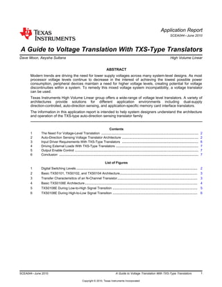
  • 2. VCC VCC VCC VCC VCC VCC VOH VIH VT VIL VOL GND 5 V 4.44 V 0.7VCC 0.5VCC 0.3VCC 0.5 V 0 V VIH VIL GND VOH VIH VT VIL VIL VOL GND 5 V 2.4 V 2 V 1.5 V 0.8 V 0.4 V 0 V VOH VIH VT VOL GND 3.3 V 2.4 V 2 V 1.5 V 0.8 V 0.4 V 0 V 2.5 V 2.0 V 1.7 V 0.7 V 0.4 V 0 V VOH VIH VIL VOL GND 1.8 V VCC-0.45V 0.65VCC 0.35VCC 0.45 V 0 V VOH VIH VIL VOL GND 1.2 V 0.65VCC 0.35VCC 0 V VCC1.5 V 0.65VCC 0.35VCC 0 V VIH VIL GND 5V CMOS 5V TTL 3.3V LVTTL 2.5V CMOS 1.8V CMOS 1.5V CMOS 1.2V CMOS The Need For Voltage-Level Translation www.ti.com 1 The Need For Voltage-Level Translation The need for voltage level translation is becoming increasingly significant in today's electronic systems. As the digital switching level standards have continued to progress toward lower voltage levels, system incompatibilities have arisen. Figure 1 illustrates the trend toward lower system voltage levels and demonstrates the incompatibilities that mixed voltage systems can face. Figure 1. Digital Switching Levels For two devices to interface reliably, the output driver voltages must be compatible with receiver input thresholds. For this condition to be met in mixed voltage systems, a voltage translator is often required. Texas Instruments offers several unique device architectures for addressing voltage translation needs. The most familiar to system designers is probably a direction-controlled buffer translator, such as the SN74AVC8T245. These translators can help remedy many problems in system voltage compatibility but require DIR (direction) control pins. If the system environment does not provide a programmable GPIO to control the direction pin, an auto-direction sensing translator architecture can provide an alternative translation solution. 2 Auto-Direction Sensing Voltage Translator Architecture If a processer GPIO input direction-control signal is not available or if one is not desired, an auto-direction sensing voltage translator can provide a robust solution. As the name implies, this type of translator does not require the use of a direction control signal, and each channel supports independent transmission or reception of data. This eliminates the need for a processor GPIO to control a DIR input, resulting in simplified software driver development as well as smaller device packaging due to reduced pin count. The two types of auto-direction sensing voltage translator architectures are TXB buffered-type and TXS switch-type. Neither type of architecture requires a DIR control signal to establish the direction of data flow. The TXB translators are designed to exclusively be connected and interfaced with a push-pull drivers and are capable of driving a light capacitive or high impedance loads in applications such as Secure Digital (SD) or Serial Peripheral Interface (SPI). See the TI application report, A Guide to Voltage Translation With TXB-Type Translators (SCEA043) for more information on the TXB-type voltage translators. Texas Instruments has developed several types of TXS-type (where the "S" indicates switch-type) translators that are designed to interface with open-drain drivers and can be used in applications such as I2 C. 2 A Guide to Voltage Translation With TXS-Type Translators SCEA044–June 2010 Copyright © 2010, Texas Instruments Incorporated
  • 3. B Gate Bias One shot T2T1 VCCA VCCB A Gate Bias N2 One- shot R1 10k R2 10k One shot One- shot V (V)IN V = 4.3 VGATE V = 3.5 VGATE V = 2.8 VGATE V = 2.5 VGATE V = 2.2 VGATE V(V)OUT www.ti.com Auto-Direction Sensing Voltage Translator Architecture 2.1 Initial Series of TXS Type Devices The initial series of TXS type devices are the TXS0101, TXS0102, and TXS0104E. The basic block diagram architecture of a single-bit (or channel) is shown in Figure 2. Figure 2. Basic TXS0101, TXS0102, and TXS0104 Architecture These TXS translators are FET-based architectures that utilize an N-channel pass-gate transistor to open and close the connection between the A-port and B-port. When a driver connected to A or B port is low, the opposite port is, in turn, pulled low by the N2 pass-gate transistor. This pass-transistor type voltage translator is ideal for down-translation and over-voltage protection. Figure 3 shows the transfer characteristics of the N2 pass-gate transistor, where the threshold voltage (VT) is approximately 1 V and the gate bias voltage (VGATE) is as shown. Figure 3. Transfer Characterisitics of an N-Channel Transistor The pass-gate transistor, N2, is on when VGS > VT. Consider first the case where one side of N2 is held low by an external driver. With the input to N2 at 0V, N2 will be “On” and the output of N2 will be held to nearly 0V due to the on-state resistance of N2. As can be seen in Figure 3, as the input voltage rises due to a rising edge, the output voltage of N2 will track the input until of N2 turns off at VGATE – VT. After N2 stops conducting, the input and output ports will continue to rise to their respective supply voltages due to 3SCEA044–June 2010 A Guide to Voltage Translation With TXS-Type Translators Copyright © 2010, Texas Instruments Incorporated
  • 4. VCCA A VCCB One-Shot One-ShotN1 P1 R1 R2 Translator One-Shot One-Shot N2 OS1 OS2 OS4 OS3 T2 T1 RpubRpua Bias Npass B P2 Translator Auto-Direction Sensing Voltage Translator Architecture www.ti.com the internal pull-up resistors on either port. Secondly, consider the case where both ports start out high. The ports will be held at static high levels due to the internal pull-up resistors. When the input port is pulled low by an external driver, N2 will begin to conduct once VGS > VT. As N2 starts to conduct the output will begin to track the input port following the curve in the Figure 3. The sinking-current required to perform this translation function must be provided by an external system driver that is connected to either the A or B ports. These pass-transistor voltage translators and their voltage clamping feature makes TXS type translators an ideal choice for applications requiring over-voltage protection and addition to voltage level translation. The signal propagation delay through the N2 transistor is extremely fast making it an elegant solution. To achieve faster data rates through the device, these translators include rising edge-rate acceleration circuitry to provide stronger ac-drive by bypassing these integrated 10-kΩ pull-up resistors through a low impedance path during low-to-high signal transitions. A one-shot (O.S.) circuit with an associated T1/T2 PMOS transistors is used to increase switching speeds for the rising-edge input signals. When a rising edge is detected by the O.S. circuit, the T1/T2 PMOS transistors turn on momentarily to rapidly drive the port high, effectively lowering the output impedance seen on that port and speeding up rising edge inputs. The combination of an N-channel pass FET, integrated 10-kΩ pull-up resistors, and edge-rate acceleration circuits makes the TXS type translators ideal for interfacing devices or systems operating at disparate voltage levels while also allowing for simple interfacing with open-drain (O.D.) as is required in I2 C, 1-wire, and MMC-card interface applications. The TXS0101, TXS0102, and TXS0104E translators also incorporate integrated pull-up resistors and higher level ESD protection which saves board space and overall BOM cost. TXS-type translators can support push-pull driving applications, and have the ability to drive slightly heavier Impedance loads than the TXB-type translators. However, the TXB-type translators may prove to be a better solution if the capacitive loading is <70pF. 2.2 Second Series of TXS Type Devices The second series switch-type translator is the TXS0108E semi-buffered type architecture and is targeted for higher speed applications. The basic block diagram of a single-bit (or channel) of this "semi-buffered" translator is shown in Figure 4. Figure 4. Basic TXS0108E Architecture 4 A Guide to Voltage Translation With TXS-Type Translators SCEA044–June 2010 Copyright © 2010, Texas Instruments Incorporated
  • 5. One- Shot Translator 1.8V Time – ns 3.3V Input signal Output signal V = 1.8 V and V = 3.3 VCCA CCB www.ti.com Auto-Direction Sensing Voltage Translator Architecture The design goals for this type of translator were to achieve faster data rates while also providing support for applications where a channel needs to start out in a low-speed open-drain (O.D.) mode, but eventually transition over to a higher-speed push-pull mode. MMC memory card applications are an example of this type of operating mode. The TXS0108E translator reliably supports high-speed data rates in excess of 60 Mbps, whereas the initial TXS series type translators supported slightly less than half this. The ability to translate down to the 1.2V operating-node is also supported in the TXS0108E device. To achieve these faster data rates, both rising-edge and falling-edge rate acceleration circuitry is incorporated for symmetrical ac-drive. Again, these accelerators bypass the integrated pull-up resistors during low-to-high and high-to-low signal transitions and speed up the output slew rate after monitoring A and B port input rising and falling edges for signal transitions. Figure 4 shows the O.S. circuit and its associated P1/P2 PMOS transistor which are used to improve switching speeds for the rising edge signal by lowering the output impedance seen on that port and speeding up the rising edge rate. Figure 5 shows a low-to-high transition. Figure 5. TXS0108E During Low-to-High Signal Transition The translator’s T1, OS3 and P2 element paths are activated when a low-to-high signal is applied at the A port. The OS3 edge-rate accelerator facilitates the fast ramping of low-to-high transition of the signal at the output. The pull-up resistors Rpua and Rpub provide dc-bias to hold the opposite port high when one of the ports is being driven high. During this acceleration phase, the output resistance of the driver is decreased to approximately 50 Ω - 70 Ω to increase the current drive capability of the device. Figure 6 shows a high-to-low transition: 5SCEA044–June 2010 A Guide to Voltage Translation With TXS-Type Translators Copyright © 2010, Texas Instruments Incorporated
  • 6. One- Shot Translator V = 1.8 V and V = 3.3 VCCA CCB 1.8V 3.3V Input signal Output signal Time – ns Input Driver Requirements With TXS-Type Translators www.ti.com Figure 6. TXS0108E During High-to-Low Signal Transition The translator’s T1, OS4 and N2 element paths are activated when a high-to-low signal is applied at the A port. The OS4 edge-rate accelerator facilitates the fast ramping of high-to-low transition of the signal at the output. The N-channel pass-gate transistor and resistors R1 and R2 provide a dc path between ports A and B. They also provide dc-bias to hold the opposite port low when one of the ports is driven low. The TXS0101/2/4 translators have fixed 10-kΩ value pull-up resistors which provide dc-bias and dc current sourcing/drive capabilities to maintain a high. A key feature that was included in the TXS0108E translator to allow it to operate better in SDIO applications is the use of "smart" pull-up resistors. This feature provides lower static power consumption (when the I/Os are passing a low), supports lower VOL values for the same size pass-gate transistor, and helps improve simultaneous switching performance. These smart pull-up resistors dynamically change value based on whether a low or a high is being passed through the I/O line, as follows: • RPUa and RPUb values are 4 kΩ when the output is driving a high. • RPUa and RPUb values are 40 kΩ when the output is driving a low. • The I/O goes into High-Z when the device is disabled via the OE pin or by pulling the either VCCA or VCCB to 0 V. The series resistance values of R1 and R2 are 150 Ω (typical). The VGATE gate bias voltage of the N-channel pass transistor is again set to a level that optimizes the switch characteristics for maximum data rate as well as minimal static supply leakage. 3 Input Driver Requirements With TXS-Type Translators The continuous dc-current "sinking" capability is determined by the external system-level driver interfaced to the TXS-type translator. For high bandwidth bidirectional SDIO circuit applications, the I/O port needs to quickly change from an input to an output and vice-vera. Therefore, a modest dc-current "sourcing" capability of 100 to 200 micro-Amps is needed and the smart pullup resistor values determine the sinking capability. The fall time (tfA, tfB) of a signal depends on the edge rate and output impedance of the external device driving these SDIO lines as well as the capacitive loading on these lines. Similarly, the tpd and max data rates also depend on the output impedance of the external driver. The values for tfA, tfB, tpd, and maximum data rates specified in the TXS data sheets assume that the output impedance of the external driver is less than 50 Ω. 6 A Guide to Voltage Translation With TXS-Type Translators SCEA044–June 2010 Copyright © 2010, Texas Instruments Incorporated
  • 7. www.ti.com Driving External Loads With TXS-Type Translators 4 Driving External Loads With TXS-Type Translators The TXS-type translators were architected for driving high-impedance loads. As such, the O.S. duration has been set to best optimize trade-offs between dynamic current consumption (ICC), load driving capability, and maximum bit-rate considerations. Careful Printed-Circuit-Board (PCB) layout practices with short trace lengths should be followed to avoid excessive capacitive loading. Ensuring proper O.S. triggering will avoid bus contention, output signal oscillations, and other adverse system-level affects. To accomplish this, PCB signal trace-lengths should be kept short enough such that the round trip delay of any reflection is less than the one-shot duration. This improves signal integrity by ensuring that any reflection sees a low impedance at the source driver. The O.S. circuits have been designed to stay on for 10 to 30 ns so the maximum capacitance of the lumped load that can be driven also depends reliably also depends directly on this one-shot duration. There is a tradeoff between achieving a maximum data rate and driving heavy capacitive loads simultaneously. With heavy capacitive loads, the one-shot can time-out before the signal is driven fully to the positive rail. In this scenario, only the pull-up resistors will pull the line high in accordance with its RC time-constant determined by the resistive and capacitive loadings. It is best to avoid this condition by driving capacitive loads less than 70pF when maximum data rate are desired. With capacitive loading >70pF, the TXS-type devices will still successfully operate at lower data rates. If the application requires an external pullup or pulldown resistor (Rpu or Rpd) special consideration must be given to the resistor value. It is important to choose a large enough Rpu or Rpd to ensure adequate VOH and VOL levels at the output port of the translator. To minimize dynamic ICC and the possibility of signal contention, the user should wait for the O.S. circuit to turn-off before applying a signal in the opposite direction. The worst-case duration is equal to the minimum pulse-width number provided in the Timing Requirements section of this data sheet. Once the O.S. is triggered and switched off, both the A and B ports must go to the same state (i.e. both high or both low) for the one-shot to trigger again. In a dc state, the output drivers maintain a low state through the pass transistor. 5 Output Enable Control The TXS devices offer low power consumption of 5 to 10 µA maximum ICC when the output enable is high. When the output enable is low, the TXS translator buffer is disabled and the outputs are placed intohigh impedance state for increased power savings. The OE input circuit is referenced to the VCCA power supply and when the device is disabled, the pullup resistors are disabled. In addition, current leakage on the A or B ports will be less than ±1 mA when the outputs are disabled. If the application does not require output enable control then the OE pin should be tied to the VCCA supply. Leaving OE floating in an indeterminate state can cause undesirable quiescent current to flow in the device which subsequently increases the overall power dissipation of the device. The outputs are also disabled and put into a high-impedance state under partial power down conditions and this feature is referred to as a VCC isolation feature. If VCCB = 0 V, the A-port is disabled. Likewise, if VCCA = 0 V, the B-port is disabled. For the TXS type translators that do not have IEC level ESD protection (i.e. ±15-kV Air-Gap and ±8-kV Contact discharge), they are fully specified for partial-power-down applications using the IOFF feature. This IOFF circuitry disables the outputs, preventing damaging current backflow through the device when these devices are powered down. 6 Conclusion The TXS translators offer system designers a good solution to remedy mixed-voltage system incompatibilities when interfacing with open-drain drivers in applications such as I2 C. These translators eliminate the need for provisioning a GPIO of a processor, since they change the direction of the data flow automatically without the use of a direction control pin. This can simplify software driver development and allows for solutions in smaller packages because of this direction control pin savings. Visit www.ti.com for data sheets for all bit-width TXS translators along with the full line of Texas Instruments voltage translators. 7SCEA044–June 2010 A Guide to Voltage Translation With TXS-Type Translators Copyright © 2010, Texas Instruments Incorporated
  • 8. IMPORTANT NOTICE Texas Instruments Incorporated and its subsidiaries (TI) reserve the right to make corrections, modifications, enhancements, improvements, and other changes to its products and services at any time and to discontinue any product or service without notice. Customers should obtain the latest relevant information before placing orders and should verify that such information is current and complete. All products are sold subject to TI’s terms and conditions of sale supplied at the time of order acknowledgment. TI warrants performance of its hardware products to the specifications applicable at the time of sale in accordance with TI’s standard warranty. Testing and other quality control techniques are used to the extent TI deems necessary to support this warranty. Except where mandated by government requirements, testing of all parameters of each product is not necessarily performed. TI assumes no liability for applications assistance or customer product design. Customers are responsible for their products and applications using TI components. To minimize the risks associated with customer products and applications, customers should provide adequate design and operating safeguards. TI does not warrant or represent that any license, either express or implied, is granted under any TI patent right, copyright, mask work right, or other TI intellectual property right relating to any combination, machine, or process in which TI products or services are used. Information published by TI regarding third-party products or services does not constitute a license from TI to use such products or services or a warranty or endorsement thereof. Use of such information may require a license from a third party under the patents or other intellectual property of the third party, or a license from TI under the patents or other intellectual property of TI. Reproduction of TI information in TI data books or data sheets is permissible only if reproduction is without alteration and is accompanied by all associated warranties, conditions, limitations, and notices. Reproduction of this information with alteration is an unfair and deceptive business practice. TI is not responsible or liable for such altered documentation. Information of third parties may be subject to additional restrictions. Resale of TI products or services with statements different from or beyond the parameters stated by TI for that product or service voids all express and any implied warranties for the associated TI product or service and is an unfair and deceptive business practice. TI is not responsible or liable for any such statements. TI products are not authorized for use in safety-critical applications (such as life support) where a failure of the TI product would reasonably be expected to cause severe personal injury or death, unless officers of the parties have executed an agreement specifically governing such use. Buyers represent that they have all necessary expertise in the safety and regulatory ramifications of their applications, and acknowledge and agree that they are solely responsible for all legal, regulatory and safety-related requirements concerning their products and any use of TI products in such safety-critical applications, notwithstanding any applications-related information or support that may be provided by TI. Further, Buyers must fully indemnify TI and its representatives against any damages arising out of the use of TI products in such safety-critical applications. TI products are neither designed nor intended for use in military/aerospace applications or environments unless the TI products are specifically designated by TI as military-grade or "enhanced plastic." Only products designated by TI as military-grade meet military specifications. Buyers acknowledge and agree that any such use of TI products which TI has not designated as military-grade is solely at the Buyer's risk, and that they are solely responsible for compliance with all legal and regulatory requirements in connection with such use. TI products are neither designed nor intended for use in automotive applications or environments unless the specific TI products are designated by TI as compliant with ISO/TS 16949 requirements. Buyers acknowledge and agree that, if they use any non-designated products in automotive applications, TI will not be responsible for any failure to meet such requirements. Following are URLs where you can obtain information on other Texas Instruments products and application solutions: Products Applications Amplifiers amplifier.ti.com Audio www.ti.com/audio Data Converters dataconverter.ti.com Automotive www.ti.com/automotive DLP® Products www.dlp.com Communications and www.ti.com/communications Telecom DSP dsp.ti.com Computers and www.ti.com/computers Peripherals Clocks and Timers www.ti.com/clocks Consumer Electronics www.ti.com/consumer-apps Interface interface.ti.com Energy www.ti.com/energy Logic logic.ti.com Industrial www.ti.com/industrial Power Mgmt power.ti.com Medical www.ti.com/medical Microcontrollers microcontroller.ti.com Security www.ti.com/security RFID www.ti-rfid.com Space, Avionics & www.ti.com/space-avionics-defense Defense RF/IF and ZigBee® Solutions www.ti.com/lprf Video and Imaging www.ti.com/video Wireless www.ti.com/wireless-apps Mailing Address: Texas Instruments, Post Office Box 655303, Dallas, Texas 75265 Copyright © 2010, Texas Instruments Incorporated