Three Key Considerations When Sourcing Your Chamber Cleaning RPS System
•
0 likes•999 views

In this infographic, learn why the chamber cleaning RPS system you use matters to the lifetime and efficiency of your wafer manufacturing process.
Recommended

Recommended
More Related Content
Similar to Three Key Considerations When Sourcing Your Chamber Cleaning RPS System
Similar to Three Key Considerations When Sourcing Your Chamber Cleaning RPS System (20)
More from Advanced Energy
More from Advanced Energy (7)
Recently uploaded
Recently uploaded (20)
Three Key Considerations When Sourcing Your Chamber Cleaning RPS System
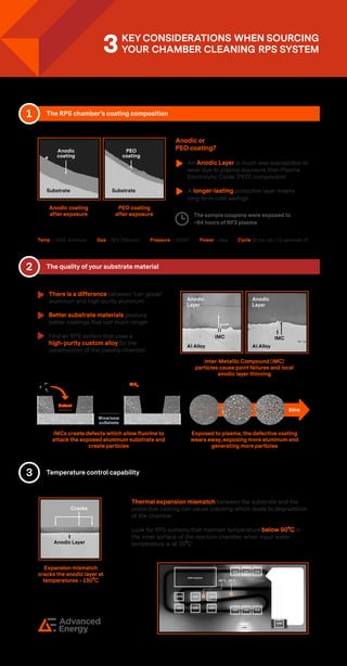
- 1. 1 The RPS chamber’s coating composition An Anodic Layer is much less susceptible to wear due to plasma exposure than Plasma Electrolytic Oxide (PEO) composition A longer-lasting protective layer means long-term cost savings Anodic coating after exposure PEO coating after exposure Process conditions: Temp = 100C minimum Gas = NF3 250sccm Pressure = 250mT Power = 5kw Cycle 20 min on / 10 seconds off 2 The quality of your substrate material There is a difference between ‘can grade’ aluminum and high-purity aluminum Better substrate materials produce better coatings that last much longer Find an RPS system that uses a high-purity custom alloy for the construction of the plasma chamber AlFx Particle Generation Mechanism: time defect Anodic layer Aluminum substrate AlFx IMCs create defects which allow fluorine to attack the exposed aluminum substrate and create particles Exposed to plasma, the defective coating wears away, exposing more aluminum and generating more particles Inter-Metallic Compound (IMC) particles cause point failures and local anodic layer thinning AI Alloy Anodic Layer AI Alloy Anodic Layer IMC IMC 3 Temperature control capability Anodic Layer Cracks Expansion mismatch cracks the anodic layer at temperatures > 150 o C Thermal expansion mismatch between the substrate and the protective coating can cause cracking which leads to degradation of the chamber Look for RPS systems that maintain temperature below 90 o C in the inner surface of the reaction chamber when input water temperature is at 35 o C. Cooling System Design and Temperature Test Result 180W 180W 160W 160W 160W 160W 100W 100W 100W 100W 100W 100W 110W 140W 20W Capacitor 38 o C 45 o C Anodic or PEO coating? The sample coupons were exposed to ~64 hours of NF3 plasma Substrate Anodic coating Substrate PEO coating