SlideShare a Scribd company logo
1 of 3
Download to read offline
Thermally	
  Conductive	
  Composites:	
  Filling	
  the	
  Performance-­‐Cost	
  
Gap	
  in	
  Thermally	
  Sensitive	
  Printed	
  Circuit	
  Boards	


By	
  Bruce	
  Hurley	
  
Global	
  Laminates	
  Inc.	


  Designing	
  a	
  thermally	
  sensitive	
  PCB,	
  one	
  could	
  be	
  forgiven	
  for	
  thinking	
  that	
  
options	
  for	
  base	
  materials	
  are	
  limited	
  to	
  products	
  like	
  an	
  insulated	
  metal	
  substrates	
  
(IMS)	
  or	
  the	
  traditional	
  FR4.	
  	
  Both	
  occupy	
  opposing	
  ends	
  of	
  the	
  performance/price	
  
spectrum	
  and	
  both	
  are	
  commonly	
  used.	
  	
  There	
  is	
  another	
  option	
  however	
  in	
  
thermally	
  conductive	
  composite	
  copper	
  clad	
  laminates.	
  	
  These	
  provide	
  new	
  thermal	
  
options	
  that	
  are	
  seldom	
  applied	
  in	
  North	
  American	
  lighting	
  and	
  heat	
  sensitive	
  
designs.	


  When	
  is	
  a	
  thermally	
  conductive	
  composite	
  base	
  laminate	
  a	
  better	
  choice	
  than	
  IMS	
  
or	
  FR4	
  for	
  a	
  lighting	
  PCB	
  design?	
  	
  The	
  general	
  thinking	
  is	
  that	
  these	
  composites	
  
(enhanced	
  CEM-­‐3)	
  fill	
  the	
  gap	
  between	
  the	
  high	
  cost/high	
  thermal	
  performance	
  of	
  
copper-­‐clad	
  aluminum	
  	
  (IMS)	
  and	
  the	
  low	
  cost/low	
  thermal	
  performance	
  of	
  an	
  FR4	
  
substrate.	
  	
  From	
  a	
  pure	
  cost	
  perspective,	
  it’s	
  true.	
  	
  In	
  general	
  you	
  could	
  expect	
  to	
  pay	
  
20%	
  -­‐25%	
  more	
  for	
  a	
  CEM-­‐3(TC)	
  product	
  over	
  a	
  similar	
  FR4	
  construction,	
  but	
  the	
  
CEM-­‐3(TC)	
  cost	
  is	
  well	
  under	
  a	
  third	
  of	
  the	
  price	
  of	
  your	
  standard	
  IMS	
  laminates.	


What	
  about	
  the	
  performance	
  gap?	
  	
  CEM-­‐3	
  is	
  old	
  technology	
  practically	
  made	
  
obsolete	
  15	
  years	
  ago	
  by	
  new	
  efficiencies	
  in	
  FR4	
  production,	
  but	
  new	
  property	
  
requirements	
  create	
  new	
  opportunities.	


  A	
  quick	
  way	
  to	
  understand	
  the	
  thermal	
  performance	
  differences	
  is	
  this:	


  FR4	
  is	
  composed	
  of	
  several	
  layers	
  of	
  woven	
  glass	
  and	
  epoxy	
  resin,	
  which	
  is	
  a	
  
great	
  insulator	
  both	
  electrically	
  and	
  thermally,	
  so	
  its	
  not	
  ideal	
  when	
  excessive	
  
surface	
  heat	
  is	
  your	
  concern.	
  	
  	
  The	
  positive	
  aspects	
  are	
  FR4	
  is	
  it’s	
  easy	
  to	
  get	
  and	
  
inexpensive.	
  	
  It	
  can	
  be	
  processed	
  cheaply	
  at	
  any	
  PCB	
  shop	
  and	
  from	
  a	
  design	
  
perspective,	
  drilling	
  and	
  plating	
  thermal	
  vias	
  is	
  easily	
  done.	
  	
  	
  These	
  vias	
  move	
  the	
  
heat	
  efficiently	
  giving	
  the	
  finished	
  board	
  much	
  better	
  thermal	
  conductivity	
  value	
  
than	
  appears	
  on	
  its	
  datasheet.	
  	
  	
  These	
  are	
  strategies	
  that	
  are	
  commonplace	
  and	
  
necessary	
  on	
  an	
  FR4	
  base	
  because	
  at	
  0.4W/mK	
  most	
  PCB’s	
  would	
  delaminate	
  under	
  
the	
  increasing	
  surface	
  heat	
  in	
  most	
  lighting	
  designs.	
  	
  Fiberglass	
  is	
  an	
  insulator,	
  so	
  
without	
  thermal	
  vias	
  today’s	
  boards	
  would	
  quickly	
  exceed	
  their	
  operating	
  
temperatures.	
  	
  The	
  one	
  negative	
  of	
  an	
  FR4	
  substrate	
  is	
  that	
  the	
  woven	
  glass	
  thermal	
  
limitations	
  can	
  restrict	
  even	
  the	
  best	
  designs	
  –	
  and	
  extra	
  drilling	
  and	
  plating	
  costs	
  
money!	
  
FR4	
  Woven	
  Glass	
  Cross	
  Section	


  The	
  insulated	
  metal	
  substrate	
  (IMS)	
  on	
  the	
  other	
  hand	
  is	
  a	
  plate	
  of	
  an	
  aluminum	
  
or	
  copper	
  alloy	
  with	
  a	
  thin	
  (.003”-­‐.005”)	
  dielectric	
  layer	
  (either	
  a	
  resin-­‐coating	
  or	
  
woven	
  glass)	
  between	
  the	
  etched	
  copper	
  surface	
  and	
  its	
  metal	
  base.	
  	
  The	
  dielectric	
  
layer	
  is	
  as	
  thin	
  as	
  electrically	
  possible	
  to	
  allow	
  the	
  heat	
  to	
  move	
  to	
  the	
  very	
  
thermally	
  conductive	
  metal	
  substrate	
  (aluminum	
  or	
  copper)	
  and	
  to	
  then	
  dissipate	
  
into	
  its	
  environment.	
  	
  Of	
  course	
  the	
  big	
  positive	
  for	
  the	
  IMS	
  is	
  thermal	
  performance,	
  
nothing	
  moves	
  the	
  heat	
  better	
  than	
  the	
  aluminum	
  or	
  copper	
  base	
  and	
  the	
  thin	
  
dielectric	
  transfers	
  it	
  from	
  the	
  surface	
  quickly.	
  	
  The	
  downside	
  is	
  the	
  price	
  and	
  
manufacturing	
  limitations.	
  	
  Although	
  the	
  price	
  of	
  a	
  bare	
  panel	
  of	
  IMS	
  has	
  dropped	
  a	
  
lot	
  in	
  the	
  last	
  5	
  years,	
  it	
  is	
  still	
  4X	
  the	
  price	
  of	
  a	
  panel	
  of	
  FR4.	
  	
  Not	
  every	
  PCB	
  shop	
  is	
  
qualified	
  to	
  manufacture	
  using	
  IMS	
  either,	
  and	
  it’s	
  a	
  process	
  that	
  is	
  hard	
  (read:	
  
expensive)	
  on	
  the	
  equipment	
  .	
  	
  There	
  are	
  also	
  fewer	
  manufacturers	
  of	
  IMS	
  base	
  
materials	
  and	
  so	
  any	
  given	
  construction	
  may	
  stretch	
  out	
  your	
  lead-­‐times	
  to	
  get	
  
product	
  in	
  the	
  pipeline.	
  	
  Another	
  limitation	
  is	
  plating,	
  metal	
  vias	
  will	
  not	
  plate	
  easily	
  
so	
  your	
  “playing	
  surface”	
  is	
  limited	
  to	
  one	
  plane.	
  	
  On	
  the	
  bright	
  side,	
  the	
  thermal	
  
dielectrics	
  continue	
  to	
  improve	
  so	
  heat	
  from	
  the	
  surface	
  is	
  transferred	
  quicker	
  than	
  
ever	
  3.0	
  and	
  5.0W/mK	
  are	
  becoming	
  more	
  common	
  and	
  the	
  technology	
  continues	
  to	
  
improve	
  filling	
  the	
  need	
  for	
  higher	
  and	
  higher	
  performance	
  IMS	
  products.	


IMS	
  with	
  coated	
  dielectric	


  The	
  CEM-­‐3(TC)	
  	
  base	
  material	
  is	
  a	
  non-­‐woven	
  blend	
  of	
  glass	
  and	
  epoxy.	
  	
  So	
  
although	
  it	
  has	
  the	
  same	
  building	
  blocks	
  of	
  FR4,	
  by	
  the	
  fact	
  that	
  it	
  is	
  a	
  “molded	
  
aggregate”	
  instead	
  of	
  a	
  series	
  of	
  woven	
  insulating	
  walls	
  allows	
  manipulation	
  in	
  the	
  
form	
  of	
  thermally	
  conductive	
  fillers.	
  	
  	
  The	
  thermal	
  performance	
  possibilities	
  of	
  a	
  TC	
  
composite	
  base	
  material	
  can	
  vary	
  widely	
  based	
  on	
  the	
  circuit	
  design.	
  	
  As	
  an	
  example,	
  
Chang	
  Chun’s	
  CCP308(TC)	
  starts	
  with	
  a	
  thermal	
  conductivity	
  of	
  1.5W/mK,	
  once	
  you	
  
add	
  to	
  the	
  cooling	
  design	
  strategies	
  like	
  thermal	
  vias	
  (CEM-­‐3	
  is	
  platable)	
  and	
  a	
  
copper-­‐clad	
  groundplane	
  the	
  thermal	
  transfer	
  from	
  the	
  surface	
  can	
  rival	
  that	
  of	
  the	
  
IMS	
  at	
  a	
  fraction	
  of	
  the	
  cost.	
  	
  	
  From	
  an	
  accessibility	
  perspective,	
  all	
  PCB	
  shops	
  are	
  
able	
  to	
  manufacture	
  with	
  CEM-­‐3	
  (TC)	
  using	
  traditional	
  FR4	
  parameters,	
  so	
  your	


Non-­‐Woven	
  CEM-­‐3(TC)	
  with	
  thermal	
  vias:	


options	
  are	
  opened.	
  	
  Another	
  important	
  factor	
  is	
  that	
  the	
  composites	
  can	
  be	
  	
  
punched	
  instead	
  of	
  drilled	
  and/or	
  routed.	
  	
  For	
  those	
  few	
  North	
  American	
  PCB	
  
makers	
  with	
  punching	
  capability,	
  or	
  if	
  you	
  are	
  depending	
  on	
  Asian	
  production	
  
facilities	
  with	
  punching	
  capability,	
  processing	
  costs	
  could	
  drop	
  dramatically	
  
depending	
  on	
  design	
  choices.	


  So	
  its	
  true,	
  the	
  enhanced	
  CEM-­‐3	
  products	
  do	
  open	
  a	
  new	
  avenue	
  to	
  explore	
  as	
  cost	
  
and	
  thermal	
  performance	
  are	
  balanced	
  at	
  design.	
  	
  	
  Considering	
  it	
  a	
  base	
  material	
  
that	
  bridges	
  the	
  gap	
  in	
  both	
  cost	
  and	
  performance	
  is	
  accurate.	
  	
  It	
  is	
  not	
  new	
  
technology,	
  just	
  newly-­‐applied	
  technology	
  that	
  creates	
  interesting	
  opportunities	
  for	
  
the	
  thermally	
  concerned	
  PCB	
  designer.	
  	
  Enhanced	
  CEM-­‐3	
  products	
  have	
  grown	
  in	
  
popularity	
  in	
  Asia	
  for	
  the	
  reasons	
  described	
  above,	
  and	
  several	
  North	
  American	
  
OEMs	
  have	
  seen	
  the	
  advantages	
  and	
  found	
  the	
  appropriate	
  applications	
  for	
  this	
  
new-­‐old	
  technology	
  in	
  innovative	
  ways.	


0	
  
20	
  
40	
  
60	
  
80	
  
100	
  
120	
  
140	
  
160	
  
0.039	
  IMS	
   0.059	
  TC+	
   0.061	
  FR4	
  
Material	
  Heat	
  Rise	
  Comparison	
  
Temperature	
  @	
  10	
  
Minutes	
  
Materials	
  testing	
  for	
  LED	
  Thermal	
  Condition	
  -­‐	
  Heat	
  rise.	
  
Comparing	
  base	
  IMS	
  to	
  std	
  FR-­‐4	
  and	
  Thermal	
  enhanced	
  CEM-­‐3	
  
Test	
  Samples	
  have	
  3	
  x	
  Cree	
  CLN6A	
  LEDs	
  -­‐	
  60.5	
  -­‐	
  101.8	
  lm	
  -­‐	
  350mA	
  nom	
  -­‐	
  1200mW	
  each	
  
Readings	
  are	
  Temperature	
  in	
  Deg.	
  F.	
  
Samples	
  are	
  with	
  Copper	
  Fill	
  in	
  circuit	
  ground	
  area	
  -­‐	
  No	
  Vias	
  	
  
Solid	
  Ground	
  Plane	
  on	
  Bottom	
  of	
  CEM-­‐3	
  &	
  FR-­‐4,	
  Bare	
  AL	
  on	
  IMS	
  parts	


Many	
  thanks	
  to	
  Aurora	
  Circuits	
  for	
  the	
  thermal	
  data.	


  Material	
   Temperature	
  @	
  10	
  Minutes	
   Description	
  
	
  0.039	
  IMS	
   101.3	
   IMS	
  AL	
  5052	
  
	
  0.059	
  TC+	
   113.5	
   CEM-­‐3	
  1/1	


  0.061	
  FR4	
   143.3	
   DS	
  FR-­‐4	
  1/1	


More Related Content

What's hot

Plasma Project fourth draft - Mike script
Plasma Project fourth draft - Mike scriptPlasma Project fourth draft - Mike script
Plasma Project fourth draft - Mike scriptMichael Garibaldi
 
Metal alloys , plain carbon steel
Metal alloys , plain carbon steelMetal alloys , plain carbon steel
Metal alloys , plain carbon steelPE Mahmoud Jad
 
Case study for material selection (Automobile Silencer)
Case study for material selection (Automobile Silencer)Case study for material selection (Automobile Silencer)
Case study for material selection (Automobile Silencer)Nishit Karkar
 
Proposed thermal circuit model for the cost effective design of fin fet
Proposed thermal circuit model for the cost effective design of fin fetProposed thermal circuit model for the cost effective design of fin fet
Proposed thermal circuit model for the cost effective design of fin fetAlexander Decker
 
11.proposed thermal circuit model for the cost effective design of fin fet
11.proposed thermal circuit model for the cost effective design of fin fet11.proposed thermal circuit model for the cost effective design of fin fet
11.proposed thermal circuit model for the cost effective design of fin fetAlexander Decker
 
Developments in electric arc furnaces
Developments in electric arc furnacesDevelopments in electric arc furnaces
Developments in electric arc furnacesRaghav Saxena
 
Introduction to modern concept of steel making through induction furnaces by ...
Introduction to modern concept of steel making through induction furnaces by ...Introduction to modern concept of steel making through induction furnaces by ...
Introduction to modern concept of steel making through induction furnaces by ...steadfast123
 
Electric arc furnace steelmaking
Electric arc furnace steelmakingElectric arc furnace steelmaking
Electric arc furnace steelmakingRecep Vatansever
 
Raw materials and coatings - basic training
Raw materials and coatings - basic trainingRaw materials and coatings - basic training
Raw materials and coatings - basic trainingRuukki
 
BROAERO_Aerolon Brochure
BROAERO_Aerolon BrochureBROAERO_Aerolon Brochure
BROAERO_Aerolon BrochureKa Man Tang
 
Steel making and alloy of steel
Steel making and alloy of steelSteel making and alloy of steel
Steel making and alloy of steelAbdul Monnaf Mohon
 
07 april 2015 the making of steel then & now by maria reza nebril
07 april 2015  the making of steel then & now by maria reza nebril07 april 2015  the making of steel then & now by maria reza nebril
07 april 2015 the making of steel then & now by maria reza nebrilEngr. Maria Reza Nebril
 
Ch 27.4 plain carbon steel
Ch 27.4 plain carbon steelCh 27.4 plain carbon steel
Ch 27.4 plain carbon steelNandan Choudhary
 
CT OCT 12 Automotive High-Temp Thermoplastic Composites Layout
CT OCT 12 Automotive High-Temp Thermoplastic Composites LayoutCT OCT 12 Automotive High-Temp Thermoplastic Composites Layout
CT OCT 12 Automotive High-Temp Thermoplastic Composites LayoutMichael Legault
 

What's hot (20)

Plasma Project fourth draft - Mike script
Plasma Project fourth draft - Mike scriptPlasma Project fourth draft - Mike script
Plasma Project fourth draft - Mike script
 
Metal alloys , plain carbon steel
Metal alloys , plain carbon steelMetal alloys , plain carbon steel
Metal alloys , plain carbon steel
 
Case study for material selection (Automobile Silencer)
Case study for material selection (Automobile Silencer)Case study for material selection (Automobile Silencer)
Case study for material selection (Automobile Silencer)
 
Proposed thermal circuit model for the cost effective design of fin fet
Proposed thermal circuit model for the cost effective design of fin fetProposed thermal circuit model for the cost effective design of fin fet
Proposed thermal circuit model for the cost effective design of fin fet
 
11.proposed thermal circuit model for the cost effective design of fin fet
11.proposed thermal circuit model for the cost effective design of fin fet11.proposed thermal circuit model for the cost effective design of fin fet
11.proposed thermal circuit model for the cost effective design of fin fet
 
Developments in electric arc furnaces
Developments in electric arc furnacesDevelopments in electric arc furnaces
Developments in electric arc furnaces
 
Introduction to modern concept of steel making through induction furnaces by ...
Introduction to modern concept of steel making through induction furnaces by ...Introduction to modern concept of steel making through induction furnaces by ...
Introduction to modern concept of steel making through induction furnaces by ...
 
Electric arc furnace steelmaking
Electric arc furnace steelmakingElectric arc furnace steelmaking
Electric arc furnace steelmaking
 
Ferrous alloys
Ferrous alloysFerrous alloys
Ferrous alloys
 
Steel Naming Conventions
Steel Naming ConventionsSteel Naming Conventions
Steel Naming Conventions
 
Raw materials and coatings - basic training
Raw materials and coatings - basic trainingRaw materials and coatings - basic training
Raw materials and coatings - basic training
 
Full material with slide
Full material with slideFull material with slide
Full material with slide
 
Mts 09 m
Mts 09 mMts 09 m
Mts 09 m
 
BROAERO_Aerolon Brochure
BROAERO_Aerolon BrochureBROAERO_Aerolon Brochure
BROAERO_Aerolon Brochure
 
Steel making and alloy of steel
Steel making and alloy of steelSteel making and alloy of steel
Steel making and alloy of steel
 
07 april 2015 the making of steel then & now by maria reza nebril
07 april 2015  the making of steel then & now by maria reza nebril07 april 2015  the making of steel then & now by maria reza nebril
07 april 2015 the making of steel then & now by maria reza nebril
 
Thermal barrier coating
Thermal barrier coatingThermal barrier coating
Thermal barrier coating
 
Ch 27.4 plain carbon steel
Ch 27.4 plain carbon steelCh 27.4 plain carbon steel
Ch 27.4 plain carbon steel
 
CT OCT 12 Automotive High-Temp Thermoplastic Composites Layout
CT OCT 12 Automotive High-Temp Thermoplastic Composites LayoutCT OCT 12 Automotive High-Temp Thermoplastic Composites Layout
CT OCT 12 Automotive High-Temp Thermoplastic Composites Layout
 
Advanced ceramics
Advanced ceramicsAdvanced ceramics
Advanced ceramics
 

Viewers also liked

CV MAY 2016- Aqeel Hadi AlSayegh
CV MAY 2016- Aqeel Hadi AlSayeghCV MAY 2016- Aqeel Hadi AlSayegh
CV MAY 2016- Aqeel Hadi AlSayeghAqeel Al Sayegh
 
John the baptist revised
John the baptist revisedJohn the baptist revised
John the baptist revisedMrsSevCTK
 
Qveda presentation11 11_09_mail
Qveda presentation11 11_09_mailQveda presentation11 11_09_mail
Qveda presentation11 11_09_mailAchuthan Kannan
 
PhD defense presentation
PhD defense presentationPhD defense presentation
PhD defense presentationAnais Jolit
 
2011 jeanette cobian src conference presentation
2011   jeanette cobian src conference presentation2011   jeanette cobian src conference presentation
2011 jeanette cobian src conference presentationMichael Gollner
 

Viewers also liked (8)

CV MAY 2016- Aqeel Hadi AlSayegh
CV MAY 2016- Aqeel Hadi AlSayeghCV MAY 2016- Aqeel Hadi AlSayegh
CV MAY 2016- Aqeel Hadi AlSayegh
 
John the baptist revised
John the baptist revisedJohn the baptist revised
John the baptist revised
 
TUGAS TIK Bab 6
TUGAS TIK Bab 6TUGAS TIK Bab 6
TUGAS TIK Bab 6
 
Qveda presentation11 11_09_mail
Qveda presentation11 11_09_mailQveda presentation11 11_09_mail
Qveda presentation11 11_09_mail
 
Evolution of Podcasts
Evolution of PodcastsEvolution of Podcasts
Evolution of Podcasts
 
PhD defense presentation
PhD defense presentationPhD defense presentation
PhD defense presentation
 
Piedras Preciosas
Piedras PreciosasPiedras Preciosas
Piedras Preciosas
 
2011 jeanette cobian src conference presentation
2011   jeanette cobian src conference presentation2011   jeanette cobian src conference presentation
2011 jeanette cobian src conference presentation
 

Similar to Thermally Conductive Composites

Super plastic Forming and Diffusion bonding in Aerospace industries
Super plastic Forming and Diffusion bonding in Aerospace industriesSuper plastic Forming and Diffusion bonding in Aerospace industries
Super plastic Forming and Diffusion bonding in Aerospace industriesRohit Katarya
 
Basic Multilayer PCB Manufacturing Training Module
Basic Multilayer PCB Manufacturing Training ModuleBasic Multilayer PCB Manufacturing Training Module
Basic Multilayer PCB Manufacturing Training ModuleKimBilugan
 
Aluminium PCB – Hitech Circuits Co., Limited, from China
Aluminium PCB – Hitech Circuits Co., Limited, from ChinaAluminium PCB – Hitech Circuits Co., Limited, from China
Aluminium PCB – Hitech Circuits Co., Limited, from ChinaCynthia HitechPCB
 
Substitution of Lead Sheath by Copper Laminated Covering in HV Cables
Substitution of Lead Sheath by Copper Laminated Covering in HV CablesSubstitution of Lead Sheath by Copper Laminated Covering in HV Cables
Substitution of Lead Sheath by Copper Laminated Covering in HV CablesLeonardo ENERGY
 
Reliability of Copper PTH for High Current Applications
Reliability of Copper PTH for High Current ApplicationsReliability of Copper PTH for High Current Applications
Reliability of Copper PTH for High Current ApplicationsEpec Engineered Technologies
 
Carbon Foam Military Applications
Carbon Foam Military ApplicationsCarbon Foam Military Applications
Carbon Foam Military ApplicationsSeminar Links
 
Penn State Capstone Project Investigating Part Warpage In Qc 10 Vs Steel
Penn State Capstone Project   Investigating Part Warpage In Qc 10 Vs SteelPenn State Capstone Project   Investigating Part Warpage In Qc 10 Vs Steel
Penn State Capstone Project Investigating Part Warpage In Qc 10 Vs Steelrsmierciak
 
White papers electric_heating_elements
White papers electric_heating_elementsWhite papers electric_heating_elements
White papers electric_heating_elementsRaymondRutledge
 
Overview of Advanced Thermal Materials
Overview of Advanced Thermal MaterialsOverview of Advanced Thermal Materials
Overview of Advanced Thermal MaterialsDr Carl Zweben
 
5 Things to Know about Conduction Cooling (CCA)
5 Things to Know about Conduction Cooling (CCA)5 Things to Know about Conduction Cooling (CCA)
5 Things to Know about Conduction Cooling (CCA)MEN Mikro Elektronik GmbH
 
5 Things to Know About Conduction Cooling
5 Things to Know About Conduction Cooling5 Things to Know About Conduction Cooling
5 Things to Know About Conduction CoolingAngela Hauber
 
5 Things to Know About Conduction Cooling (CCA)
5 Things to Know About Conduction Cooling (CCA)5 Things to Know About Conduction Cooling (CCA)
5 Things to Know About Conduction Cooling (CCA)MEN Micro
 
IRJET- Development of MGO-EPOXY Composites with Enhanced Thermal Conductivity
IRJET- Development of MGO-EPOXY Composites with Enhanced Thermal ConductivityIRJET- Development of MGO-EPOXY Composites with Enhanced Thermal Conductivity
IRJET- Development of MGO-EPOXY Composites with Enhanced Thermal ConductivityIRJET Journal
 
5 Things to Know about Conduction Cooling (CCA)
5 Things to Know about Conduction Cooling (CCA)5 Things to Know about Conduction Cooling (CCA)
5 Things to Know about Conduction Cooling (CCA)MEN Micro
 
Using Heavy Copper and EXTREME Copper in PCB Design and Fabrication for Maxim...
Using Heavy Copper and EXTREME Copper in PCB Design and Fabrication for Maxim...Using Heavy Copper and EXTREME Copper in PCB Design and Fabrication for Maxim...
Using Heavy Copper and EXTREME Copper in PCB Design and Fabrication for Maxim...Epec Engineered Technologies
 

Similar to Thermally Conductive Composites (20)

Ceramic PCB ceramic substrate, ceramic circuit board
Ceramic PCB ceramic substrate, ceramic circuit boardCeramic PCB ceramic substrate, ceramic circuit board
Ceramic PCB ceramic substrate, ceramic circuit board
 
Super plastic Forming and Diffusion bonding in Aerospace industries
Super plastic Forming and Diffusion bonding in Aerospace industriesSuper plastic Forming and Diffusion bonding in Aerospace industries
Super plastic Forming and Diffusion bonding in Aerospace industries
 
Basic Multilayer PCB Manufacturing Training Module
Basic Multilayer PCB Manufacturing Training ModuleBasic Multilayer PCB Manufacturing Training Module
Basic Multilayer PCB Manufacturing Training Module
 
Aluminium PCB – Hitech Circuits Co., Limited, from China
Aluminium PCB – Hitech Circuits Co., Limited, from ChinaAluminium PCB – Hitech Circuits Co., Limited, from China
Aluminium PCB – Hitech Circuits Co., Limited, from China
 
Substitution of Lead Sheath by Copper Laminated Covering in HV Cables
Substitution of Lead Sheath by Copper Laminated Covering in HV CablesSubstitution of Lead Sheath by Copper Laminated Covering in HV Cables
Substitution of Lead Sheath by Copper Laminated Covering in HV Cables
 
Reliability of Copper PTH for High Current Applications
Reliability of Copper PTH for High Current ApplicationsReliability of Copper PTH for High Current Applications
Reliability of Copper PTH for High Current Applications
 
Carbon Foam Military Applications
Carbon Foam Military ApplicationsCarbon Foam Military Applications
Carbon Foam Military Applications
 
eDRAM-Crolles_2005
eDRAM-Crolles_2005eDRAM-Crolles_2005
eDRAM-Crolles_2005
 
Penn State Capstone Project Investigating Part Warpage In Qc 10 Vs Steel
Penn State Capstone Project   Investigating Part Warpage In Qc 10 Vs SteelPenn State Capstone Project   Investigating Part Warpage In Qc 10 Vs Steel
Penn State Capstone Project Investigating Part Warpage In Qc 10 Vs Steel
 
White papers electric_heating_elements
White papers electric_heating_elementsWhite papers electric_heating_elements
White papers electric_heating_elements
 
Overview of Advanced Thermal Materials
Overview of Advanced Thermal MaterialsOverview of Advanced Thermal Materials
Overview of Advanced Thermal Materials
 
Project PPTby ckp
Project PPTby ckpProject PPTby ckp
Project PPTby ckp
 
5 Things to Know about Conduction Cooling (CCA)
5 Things to Know about Conduction Cooling (CCA)5 Things to Know about Conduction Cooling (CCA)
5 Things to Know about Conduction Cooling (CCA)
 
R & D Booklet Final
R & D Booklet FinalR & D Booklet Final
R & D Booklet Final
 
Pcm roof ii
Pcm roof iiPcm roof ii
Pcm roof ii
 
5 Things to Know About Conduction Cooling
5 Things to Know About Conduction Cooling5 Things to Know About Conduction Cooling
5 Things to Know About Conduction Cooling
 
5 Things to Know About Conduction Cooling (CCA)
5 Things to Know About Conduction Cooling (CCA)5 Things to Know About Conduction Cooling (CCA)
5 Things to Know About Conduction Cooling (CCA)
 
IRJET- Development of MGO-EPOXY Composites with Enhanced Thermal Conductivity
IRJET- Development of MGO-EPOXY Composites with Enhanced Thermal ConductivityIRJET- Development of MGO-EPOXY Composites with Enhanced Thermal Conductivity
IRJET- Development of MGO-EPOXY Composites with Enhanced Thermal Conductivity
 
5 Things to Know about Conduction Cooling (CCA)
5 Things to Know about Conduction Cooling (CCA)5 Things to Know about Conduction Cooling (CCA)
5 Things to Know about Conduction Cooling (CCA)
 
Using Heavy Copper and EXTREME Copper in PCB Design and Fabrication for Maxim...
Using Heavy Copper and EXTREME Copper in PCB Design and Fabrication for Maxim...Using Heavy Copper and EXTREME Copper in PCB Design and Fabrication for Maxim...
Using Heavy Copper and EXTREME Copper in PCB Design and Fabrication for Maxim...
 

Thermally Conductive Composites

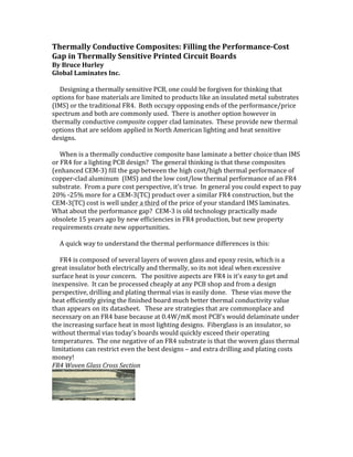
  • 1. Thermally  Conductive  Composites:  Filling  the  Performance-­‐Cost   Gap  in  Thermally  Sensitive  Printed  Circuit  Boards           By  Bruce  Hurley   Global  Laminates  Inc.              Designing  a  thermally  sensitive  PCB,  one  could  be  forgiven  for  thinking  that   options  for  base  materials  are  limited  to  products  like  an  insulated  metal  substrates   (IMS)  or  the  traditional  FR4.    Both  occupy  opposing  ends  of  the  performance/price   spectrum  and  both  are  commonly  used.    There  is  another  option  however  in   thermally  conductive  composite  copper  clad  laminates.    These  provide  new  thermal   options  that  are  seldom  applied  in  North  American  lighting  and  heat  sensitive   designs.              When  is  a  thermally  conductive  composite  base  laminate  a  better  choice  than  IMS   or  FR4  for  a  lighting  PCB  design?    The  general  thinking  is  that  these  composites   (enhanced  CEM-­‐3)  fill  the  gap  between  the  high  cost/high  thermal  performance  of   copper-­‐clad  aluminum    (IMS)  and  the  low  cost/low  thermal  performance  of  an  FR4   substrate.    From  a  pure  cost  perspective,  it’s  true.    In  general  you  could  expect  to  pay   20%  -­‐25%  more  for  a  CEM-­‐3(TC)  product  over  a  similar  FR4  construction,  but  the   CEM-­‐3(TC)  cost  is  well  under  a  third  of  the  price  of  your  standard  IMS  laminates.       What  about  the  performance  gap?    CEM-­‐3  is  old  technology  practically  made   obsolete  15  years  ago  by  new  efficiencies  in  FR4  production,  but  new  property   requirements  create  new  opportunities.                A  quick  way  to  understand  the  thermal  performance  differences  is  this:                FR4  is  composed  of  several  layers  of  woven  glass  and  epoxy  resin,  which  is  a   great  insulator  both  electrically  and  thermally,  so  its  not  ideal  when  excessive   surface  heat  is  your  concern.      The  positive  aspects  are  FR4  is  it’s  easy  to  get  and   inexpensive.    It  can  be  processed  cheaply  at  any  PCB  shop  and  from  a  design   perspective,  drilling  and  plating  thermal  vias  is  easily  done.      These  vias  move  the   heat  efficiently  giving  the  finished  board  much  better  thermal  conductivity  value   than  appears  on  its  datasheet.      These  are  strategies  that  are  commonplace  and   necessary  on  an  FR4  base  because  at  0.4W/mK  most  PCB’s  would  delaminate  under   the  increasing  surface  heat  in  most  lighting  designs.    Fiberglass  is  an  insulator,  so   without  thermal  vias  today’s  boards  would  quickly  exceed  their  operating   temperatures.    The  one  negative  of  an  FR4  substrate  is  that  the  woven  glass  thermal   limitations  can  restrict  even  the  best  designs  –  and  extra  drilling  and  plating  costs   money!   FR4  Woven  Glass  Cross  Section        
  • 2.          The  insulated  metal  substrate  (IMS)  on  the  other  hand  is  a  plate  of  an  aluminum   or  copper  alloy  with  a  thin  (.003”-­‐.005”)  dielectric  layer  (either  a  resin-­‐coating  or   woven  glass)  between  the  etched  copper  surface  and  its  metal  base.    The  dielectric   layer  is  as  thin  as  electrically  possible  to  allow  the  heat  to  move  to  the  very   thermally  conductive  metal  substrate  (aluminum  or  copper)  and  to  then  dissipate   into  its  environment.    Of  course  the  big  positive  for  the  IMS  is  thermal  performance,   nothing  moves  the  heat  better  than  the  aluminum  or  copper  base  and  the  thin   dielectric  transfers  it  from  the  surface  quickly.    The  downside  is  the  price  and   manufacturing  limitations.    Although  the  price  of  a  bare  panel  of  IMS  has  dropped  a   lot  in  the  last  5  years,  it  is  still  4X  the  price  of  a  panel  of  FR4.    Not  every  PCB  shop  is   qualified  to  manufacture  using  IMS  either,  and  it’s  a  process  that  is  hard  (read:   expensive)  on  the  equipment  .    There  are  also  fewer  manufacturers  of  IMS  base   materials  and  so  any  given  construction  may  stretch  out  your  lead-­‐times  to  get   product  in  the  pipeline.    Another  limitation  is  plating,  metal  vias  will  not  plate  easily   so  your  “playing  surface”  is  limited  to  one  plane.    On  the  bright  side,  the  thermal   dielectrics  continue  to  improve  so  heat  from  the  surface  is  transferred  quicker  than   ever  3.0  and  5.0W/mK  are  becoming  more  common  and  the  technology  continues  to   improve  filling  the  need  for  higher  and  higher  performance  IMS  products.     IMS  with  coated  dielectric                  The  CEM-­‐3(TC)    base  material  is  a  non-­‐woven  blend  of  glass  and  epoxy.    So   although  it  has  the  same  building  blocks  of  FR4,  by  the  fact  that  it  is  a  “molded   aggregate”  instead  of  a  series  of  woven  insulating  walls  allows  manipulation  in  the   form  of  thermally  conductive  fillers.      The  thermal  performance  possibilities  of  a  TC   composite  base  material  can  vary  widely  based  on  the  circuit  design.    As  an  example,   Chang  Chun’s  CCP308(TC)  starts  with  a  thermal  conductivity  of  1.5W/mK,  once  you   add  to  the  cooling  design  strategies  like  thermal  vias  (CEM-­‐3  is  platable)  and  a   copper-­‐clad  groundplane  the  thermal  transfer  from  the  surface  can  rival  that  of  the   IMS  at  a  fraction  of  the  cost.      From  an  accessibility  perspective,  all  PCB  shops  are   able  to  manufacture  with  CEM-­‐3  (TC)  using  traditional  FR4  parameters,  so  your       Non-­‐Woven  CEM-­‐3(TC)  with  thermal  vias:       options  are  opened.    Another  important  factor  is  that  the  composites  can  be    
  • 3. punched  instead  of  drilled  and/or  routed.    For  those  few  North  American  PCB   makers  with  punching  capability,  or  if  you  are  depending  on  Asian  production   facilities  with  punching  capability,  processing  costs  could  drop  dramatically   depending  on  design  choices.              So  its  true,  the  enhanced  CEM-­‐3  products  do  open  a  new  avenue  to  explore  as  cost   and  thermal  performance  are  balanced  at  design.      Considering  it  a  base  material   that  bridges  the  gap  in  both  cost  and  performance  is  accurate.    It  is  not  new   technology,  just  newly-­‐applied  technology  that  creates  interesting  opportunities  for   the  thermally  concerned  PCB  designer.    Enhanced  CEM-­‐3  products  have  grown  in   popularity  in  Asia  for  the  reasons  described  above,  and  several  North  American   OEMs  have  seen  the  advantages  and  found  the  appropriate  applications  for  this   new-­‐old  technology  in  innovative  ways.           0   20   40   60   80   100   120   140   160   0.039  IMS   0.059  TC+   0.061  FR4   Material  Heat  Rise  Comparison   Temperature  @  10   Minutes   Materials  testing  for  LED  Thermal  Condition  -­‐  Heat  rise.   Comparing  base  IMS  to  std  FR-­‐4  and  Thermal  enhanced  CEM-­‐3   Test  Samples  have  3  x  Cree  CLN6A  LEDs  -­‐  60.5  -­‐  101.8  lm  -­‐  350mA  nom  -­‐  1200mW  each   Readings  are  Temperature  in  Deg.  F.   Samples  are  with  Copper  Fill  in  circuit  ground  area  -­‐  No  Vias     Solid  Ground  Plane  on  Bottom  of  CEM-­‐3  &  FR-­‐4,  Bare  AL  on  IMS  parts     Many  thanks  to  Aurora  Circuits  for  the  thermal  data.                  Material   Temperature  @  10  Minutes   Description    0.039  IMS   101.3   IMS  AL  5052    0.059  TC+   113.5   CEM-­‐3  1/1      0.061  FR4   143.3   DS  FR-­‐4  1/1