The document presents two new concepts for efficiently joining metals to polymer composites without adhesives or fasteners: 1) Using a metal foam infiltrated with thermoplastic matrix to join carbon fiber composite to metal. 2) Using "Z-pins" anchored in metal and ultrasonically inserted into uncured composite prepreg. Prototype single and double lap shear joints were manufactured for each concept and tested. Initial results showed the metal foam joints withstood 5.6 kN and Z-pin joints withstood 31 kN before failure, demonstrating potential to transfer significant loads through these novel metal-composite joints.
1. Extended Abstract
New approaches to metal-composite joining
A Joesbury1
, D Ayre2
, I K Partridge2
, P Colegrove1
and S W Williams1
1
Welding Engineering Research Centre and 2
Composites Centre, Cranfield University,
Cranfield, Bedford, MK43 0AL
The contribution presents results from a new study that has the aim of achieving efficient
bonding between metals and polymer composites, without recourse to mechanical means
such as bolting and riveting and without the use of standard structural adhesives. Two
different design concepts for a highly loaded metal/composite lap-shear joint are proposed.
The new elements in this joining study are the use of metal foams infiltrated with
thermoplastic matrix, and exploitation of metallic ‘Z-pins’ anchored in a metallic adherend
and inserted into the uncured prepreg adherend by the use of an ultrasonic hammer.
Manufacturing issues and the mechanical performance of the prototype joints are evaluated.
The initial investigation demonstrates that significant loads can be transferred through these
novel metal-composite joints.
Keywords: joining, composite, CFRP, metal foam, PEEK, thermoplastic, dissimilar materials,
CMT, Z-pin
2. 1. Introduction
Fibre reinforced composites and metals are both widely used structural materials. These two
materials have significantly different properties, manufacturing processes, and in-service
behaviour, but are frequently used together within a single load carrying structure. Joining
methods between composites and metals almost exclusively rely on the joining techniques of
adhesive bonding, the use of mechanical fasteners, or a combination of the two. Due to the
differences between the two materials both adhesive bonding and mechanical fastening result
in significant penalties in terms of structural efficiency. This work investigates alternative
methods for joining composites to metals, with the aim of producing joints with greater
structural efficiency.
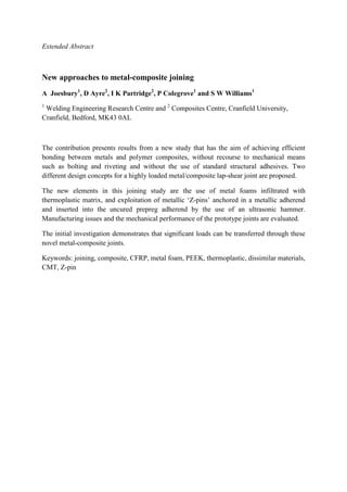
The infiltrated metal foam joint concept, joining a carbon fibre reinforced plastic (CFRP) to
metal, is illustrated in figure 1. This joint concept makes use of a polymer infused metal foam
to act as an intermediary material, which compensates for the differences in physical
properties between metal and composite materials1
, while making use of established metal-to-
metal and plastic-to-plastic joining methods. The thermoplastic chosen for this work was
PEEK.
Figure 1 Diagram of infiltrated metal foam joint concept
The anchored metallic ‘Z-Pins’ joint concept is illustrated in figure 2. This joint concept
incorporates aspects from both adhesive bonding and mechanical fastening. The pins,
attached by cold metal transfer welding (CMT), have a sufficiently small diameter such that
damage to the composite reinforcing fibres is significantly reduced when compared with
traditional fastening methods (e.g. rivets, bolts). When the pins are embedded into the
composite the joint benefits from an increased adhesive bonding areal density, composite
through thickness reinforcement at joining interface, and shear loading of metallic surface
features at the joining interface.
Figure 2 Diagram of anchored metallic ‘Z-Pin’ joint concept
2. Infiltrated metal foams
2.1. Materials and joint geometry
The infiltrated metal foam prototype joint consisted of a 3mm thick 304L stainless steel plate
joined to a 2mm thick laminate of unidirectional CFRP, APC-2, by the means of a PEEK
infused nickel metal foam intermediate material of 5mm thickness. A single lap shear joint of
40mm width with an overlap of 25mm was constructed.
Thermoplastic matrix CFRP to PEEK
infused metal foam: fusion joint
Metal plate to metal foam: laser
heating brazed joint
Pins encapsulated in CFRP
Metal plate with pins attached by
CMT-Pin welding process
3. 2.2. Manufacturing method
2.2.1. Laser brazing
The metal foam was first joined to
the braze filler metal are significantly
nickel metal foam2
, unlike direct
metal foam. The heat required to form the braze joint was provided by laser energy applied
indirectly, through the metal plate
2.2.2. Polymer infiltration and joining to composite
A heated platen press was used to raise t
subsequently apply a force to
constructed within the press to
piece of APC-2 carbon fibre composite and the PEEK as it was infused into the metal foam
This resulted in a single lap shear joint
metal foam and the brazed joint
Figure 3 Micrograph of PEEK infused nickel foam
3. Anchored metallic ‘Z
3.1. Materials and joint geometry
The anchored metallic ‘Z-Pin’
plate with the joint interface
steel pins. A regular array of 35 pins
then embedded into a quasi-isot
joint (DLS) of width 25mm and overlap of 30mm.
3.2. Manufacturing method
The Fronius developed CMT pin
interface area of the double lap shear joint. To improve
to methods used in previous work
an ultrasonic horn. The laminate
micrograph of the interaction between the pins and the quasi
4(b) shows the double lap shear joint after tensile failure.
fig.4(b), shows that several failure mechanisms are present: adhesion f
failure, pin necking, and pin shear fracture.
Manufacturing method
razing
The metal foam was first joined to a metal plate by brazing. Temperatures required to melt
significantly lower than the melting temperature of the
direct metal fusion joining temperatures which would destroy the
The heat required to form the braze joint was provided by laser energy applied
through the metal plate.
er infiltration and joining to composite
A heated platen press was used to raise the temperature of the PEEK to
push the PEEK melt into the porous metal foam.
constructed within the press to allow simultaneous formation of a fusion bond between the
2 carbon fibre composite and the PEEK as it was infused into the metal foam
This resulted in a single lap shear joint (SLS). Figure 3 shows a cross-section of
joint to metal plate.
Micrograph of PEEK infused nickel foam joined by silver
stainless steel plate.
Anchored metallic ‘Z-Pins’
Materials and joint geometry
Pin’ prototype joint consisted of a 3mm thick 304
the joint interface surface of the plate being structured with an array
A regular array of 35 pins was formed on both sides of the plate and
isotropic lay-up of M21/T700 prepreg to form a double lap shear
of width 25mm and overlap of 30mm.
Manufacturing method
The Fronius developed CMT pin-welding process4
was used to apply the array of
e lap shear joint. To improve the joint manufacturability compared
to methods used in previous work5
, these pins were then forced into the prepreg
he laminate was subsequently cured in an autoclave. Fig
micrograph of the interaction between the pins and the quasi-isotropic laminate and fig
4(b) shows the double lap shear joint after tensile failure. Visual inspection of the
that several failure mechanisms are present: adhesion f
and pin shear fracture.
Temperatures required to melt
lower than the melting temperature of the delicate
which would destroy the
The heat required to form the braze joint was provided by laser energy applied
the PEEK to 360ºC and
into the porous metal foam. A mould was
a fusion bond between the
2 carbon fibre composite and the PEEK as it was infused into the metal foam3
.
section of the infused
silver-copper braze to
304L stainless steel
an array of stainless
both sides of the plate and this plate was
to form a double lap shear
apply the array of pins to the
the joint manufacturability compared
the prepreg by the use of
Figure 4(a) shows a
isotropic laminate and figure
Visual inspection of the failed joint,
that several failure mechanisms are present: adhesion failure, laminate
4. (a) (b)
Figure 4 Micrograph of interaction between composite laminate and pins (a).
Photograph showing damage at failure of double lap shear tensile test (b).
4. Preliminary Mechanical Test Results
The lap joints constructed using resin infused metal foam and CMT-pins were tested in
tension to establish the load transfer capabilities and the mode of joint failure. The initial
findings are presented in table 1.
Table 1.
Results from mechanical testing of lap shear joints.
Joint Failure Load kN Failure Mode
Infiltrated Metal Foam
SLS
5.6 Progressive, initial failure at
brazed joint
Anchored metallic ‘Z-
Pins’ DLS
31.0 Progressive, initial adhesive
failure
Typical CRFP/metal
adhesive DLS5
21.5 Catastrophic adhesive failure
5. Conclusions
The work presented here is an overview of the initial investigations of prototype joints
constructed to investigate the feasibility of the infiltrated metal foam and anchored metallic
‘Z-Pin’ joining concepts. It has been demonstrated that manufacturability of these joints is
realistic and that the joints are capable of transferring a significant load. Further work is
currently in progress to investigate more fully the performance and characteristics of these
joining techniques.
Acknowledgements
The work presented here was funded through the Cranfield University IMRC.
References
1. Shirzadi, A. A., Zhu, Y. and Bhadeshia, H. (2008), "Joining ceramics to metals using
metallic foam", Materials Science and Engineering A, vol. 496, no. 1-2, pp. 501-506.
5. 2. Longerich, S., Piontek, D., Ohse, P., Harms, A., Dilthey, U., Angel, S. and Bleck, W.
(2007), "Joining Strategies for Open Porous Metallic Foams on Iron and Nickel Base
Materials", Advanced Engineering Materials, vol. 9, no. 8, pp. 670-678.
3. Cantwell, W. J., Davies, P., Bourban, P. E., Jar, P. Y., Richard, H. and Kausch, H. H.
(1990), "Thermal joining of carbon fibre reinforced PEEK laminates", Composite
Structures, vol. 16, no. 4, pp. 305-321.
4. Fronius International GmbH (2009), If it can't be welded, pin it - Fronius International
GmbH - Press releases, available at: http://www.fronius.com/cps/rde/xchg/SID-
477DDFBB-73E6514D/fronius_international/hs.xsl/68_16640_ENG_HTML.htm
(accessed 05/31).
5. Ucsnik, S., Scheerer, M., Zaremba, S. and Pahr, D. H. (2010), "Experimental
investigation of a novel hybrid metal-composite joining technology.", Composites Part
A: Applied Science and Manufacturing, vol. 41, no. 3, pp. 369-374.