1. Surface preparation of stainless steel 316L,
bronze CW451K and titanium Ti6Al4V for
bonding to polyurethane in marine cable
connector assemblies
Z. Makama1
, I. Doble2
, D. Nicolson2
, M. E. Webb2
, I. B. Beech1
, S. A. Campbell1
and J. R. Smith*1
Grit-blasting of stainless steel 316L,
bronze CW451K and titanium Ti6Al4V
used in marine/offshore cable
connectors is described. For the former,
no change in roughness was observed
when using brown angular Al2O3 or
black SiC grit of the same particle size.
Finer SiC grit produced less rough
surfaces. Blast pressure increased
stainless steel roughness using SiC,
although this was largely unchanged
using Al2O3. Increased grit-embedment
was observed using Al2O3 grit, which
led to decreased bond strength to over-
moulded primer and polyurethane.
Ti6Al4V and stainless steel yielded the
same roughness using Al2O3, although
bronze had a rougher surface. Grit-
embedment decreased in the order
stainless steel.bronze.Ti6Al4V, in line
with hardness values.
Introduction
Metal cable connector assemblies find
wide application in harsh marine/
offshore environments, such as power
transmission, fibre optic and
telecommunications cables, and are
also found on remotely operated
vehicles, underwater surveillance and
submarine sonar systems.1
A typical cable connector assembly is
comprised of a cable that is electrically
wired at one or both ends to a metal
connector head/female made up of a
stainless steel or monel body (back-
shell) with or without a sliding bronze
locking-ring (Fig. 1). Connector heads
can be made from other metal alloys,
such as titanium. The cable is first
electrically wired to the connector head
and/or female connector, and the metal
connector back-shell surface is
prepared, primed with a coating and
then over-moulded with a castable
encapsulation polymer, such as
polyurethane (PU), neoprene,
polyethylene or polychloroprene.1–3
These materials seal the interfaces
between the cable and the connector-
head, via the back-shell, and form a
polymer-to-polymer and a polymer-to-
metal bond between the cable and the
back-shell, respectively (Fig. 1b). The
interface is sealed into a moulded,
finished product that provides adequate
protection from the environment
(Fig. 2a and b).
The delamination of the polymeric
over-mould (primer coating and/or
polymer) from the metal connector
back-shell is one of the common failure
mechanisms encountered in marine
cable connector assemblies (Fig. 2c
and d).4
Cathodic delamination failures
usually originate in the vicinity of a
coating defect which is cathodically
polarised whilst immersed in an
electrolyte.1,2,5–10
The failure or
separation of the PU over-mould from
the metal connector back-shells is
usually characterised by three distinct
failure modes:
(i) failure at the metal/primer
interface
(ii) failure at the primer/PU
interface
(iii) failure at both of these
interfaces (mixed mode
failure).5
Polymer-to-metal adhesion is
enhanced when metal surfaces are
roughened prior to coating.11–14
Most
manufacturers therefore subject metal
surfaces to some form of roughening
pre-treatment prior to coating
application. This provides a mechanical
interlocking (‘keying’) effect between
the surfaces and also increases the
effective surface area of the metal and
hence the number of molecular bonds
to area ratio at the metal/polymer
interface.11–18
Surface roughness and
cleanliness are desirable qualities of
pre-treated metal substrates, as they
are essential for achieving optimum
adhesion and durability in specified
service environments.16,17
Grit-blasting is one of the most
common, cost-effective and efficient
metal pre-treatments.11–15,19–21
Abrading methods and/or abrasive
materials must be carefully selected to
achieve optimal roughening and
surface cleanliness, especially where
the finished products will be immersed
in an electrolyte during service.13,14,22
An overview of abrasive material
selection was recently published in
Transactions.23
Certain abrasive types
and sizes are known to become
embedded in, or leave residues on
the surface of the substrate during
grit-blasting.11,20,22,24
While in some
cases this may not be detrimental,
embedded abrasive particles may
contain solvent-soluble contaminants,
which could be detrimental to polymer-
to-metal bonding in immersion
services.20,22
Choosing the right
abrading methods and materials has a
significant effect on the surface finish
obtained.22–27
Here, we examine the surface
topographies of grit-blasted stainless
steel 316L, bronze CW451K and
titanium Ti6Al4V and measure their
1
School of Pharmacy and Biomedical Sciences,
University of Portsmouth, St Michael’s Building,
White Swan Road, Portsmouth PO1 2DT, UK
2
PDM Neptec Ltd, 4-6 Alton Business Centre,
Omega Park, Alton, Hampshire GU34 2YU, UK
*For correspondence: james.smith@port.ac.uk
Presented in part by ZM at the Dr Sheelagh
Campbell Memorial Symposium, at the Royal
Society of Chemistry, The Chemistry Centre,
Burlington House, Piccadilly, London, 8th April
2011.
B U L L E T I N
ß 2011 Institute of Metal Finishing
Published by Maney on behalf of the Institute
DOI 10.1179/174591911X13125496893308 Transactions of the Institute of Metal Finishing 2011 VOL 89 NO 5 237
2. surface roughness, identify extraneous
materials on grit-blasted surfaces and
find methods for reducing or
eliminating them and investigate the
effect of grit material and/or grit-
blasting pressures on the surface
cleanliness of metal substrates. The
main objective of the work was to
determine the optimum surface
roughness and cleanliness required to
achieve optimum adhesion of selected
polymer-to-metal systems in
immersion service and hence reduce
the effect of failures by cathodic
delamination experienced in cable
connector assemblies used in marine
environments. Most of the work has
been focused on stainless steel, since
this material is most widely used for
this application. Ti6Al4V is known for its
high corrosion resistance.28
Brown
angular aluminium oxide (Al2O3) and
black silicon carbide (SiC) rich grits
were used.
Experimental
Materials
Stainless steel 316L, bronze CW451K
and Ti6Al4V alloys (Tables 1 and 2)29,30
were obtained from Aaron Metal and
Plastics Suppliers Ltd, Bristol, UK.
Al2O3 and SiC rich grits were supplied
by Vixen Surface Treatment Ltd,
Stockton-on-Tees, UK and Guyson
International Ltd, North Yorkshire, UK,
respectively. Brown angular Al2O3 and
black SiC, each of different FEPA mesh
sizes, were used as received
(Table 3).29,30
Fresh grit samples were
used prior to the investigations,
although these materials may be
recycled.23
A wash primer, PR24,
supplied by Lords Corporation Ltd,
Manchester, UK, and Castable PU
(EMC80A) was supplied by DOW
Hyperlast, Derbyshire, UK.
2 Photographs of a moulded cable connector assembly showing: a, b regions
of sealed polymer-to-metal interface, c onset of delamination at the interface
and d regions of adhesion failure and the metal/primer/PU interface sus-
pected to be due to cathodic delamination
1 a a typical moulded cable connector assembly; b schematic of a cable connector assembly, showing polymer-to-metal
bond interface region known to be susceptible to cathodic delamination failures
B U L L E T I N
238 Transactions of the Institute of Metal Finishing 2011 VOL 89 NO 5
3. Grit-blasting
Grit-blasting was carried out in a Vixen
Jetair VM42 blast cabinet (Vixen
Surface Treatment Ltd, Stockton-on-
Tees, UK). This is an open nozzle
recycleable indoor type grit-blasting
system in which grit is fed from a
hopper via a hose to a blasting nozzle
using compressed air. Metal substrates
were cut into 2062063 mm sections.
Prior to surface preparation, substrates
were cleaned in acetone using a hard
bristle hand brush. The surfaces were
then grit-blasted according to PDM
standard PDM/STD/3009.31
A tungsten
carbide blast nozzle (8 mm diameter,
located at an angle of about 75–90u),
separated from the substrate surface
by about 6–10 cm, was used. The
nozzle was continuously and slowly
moved backwards and forward across
the metal surface until an even matt
finish was achieved.31
Blasting
pressures of 30–80 psi (207–
552 kN m22
) were used for surface
pre-treatment.
Scanning electron microscopy
Grit-blasted samples were examined
using a JEOL digital analytical scanning
electron microscope (SEM) JSM-6100
fitted with energy dispersive X-ray
spectrometry (EDS) to identify the
elemental compositions of treated
surfaces. Acquisition of SEM images
was carried out using a voltage range of
10–20 kV and a current of 90–100 mA
on a tungsten filament cathode. Prior to
imaging, the surfaces of the grit-blasted
metal substrates were washed in
acetone and any debris removed by a
stream of clean, dry compressed air.
Samples were then mounted on
sample holders using plastic
conductive carbon cement and placed
in the SEM specimen chamber.
Surface roughness
Surface roughness measurements of
grit-blasted materials were carried out
using a Tally-surf Mitutoyo-Surftracer
SV-C524 (Mitutoyo UK, Andover,
Hants., UK) coupled to a Surtronic 3P
Taylor-Hobson system (Taylor-Hobson
UK, Leics., UK). Metal substrates, grit-
blasted using different grit materials
and particle sizes, were analysed to
establish the surface roughness
generated. Prior to measurements, grit-
blasted metal samples were again
subjected to a stream of dry
compressed air to remove loose
particles. The test sample pieces
(2062063 mm) were attached to a
sample mounting block using double-
sided adhesive tape and their
roughness measured by the stylus arm
of the Tally-surf. As the stylus arm
moved across the surface of the
substrate, it moved its diamond tip
stylus between roughness spacings on
the surface of the sample while the
skid slid along the surface unaffected
by the roughness spacing due to its
larger radius of curvature (Fig. 3). The
movement of the stylus relative to the
skid was detected and converted to
electrical signals related to surface
roughness. Three readings were
obtained from different areas of each
sample and an average value
determined. The arithmetic roughness
average (Ra), which could be related to
roughness numbers (N1–N12) for easy
evaluation, was the main parameter
used.32–34
Other roughness
parameters, such as root mean square
roughness (Rq), the maximum height of
profile above the mean position (Rp)
and the maximum depth of profile from
the mean line (Rv), were also
obtained.34
Bond testing
To examine the effect of grit-blasting
on adhesion, stainless steel metal
substrates (10062563 mm thick test
pieces) were machined and grit-blasted
using Al2O3 or SiC rich grit. They were
then coated with primer, allowed to dry
and over-moulded with castable PU in
permanent open-fill PU moulds. Prior to
moulding, about 10 mm of one end of
the coated metal strips was masked
with adhesive tape, to create an
unbonded free end for sample bond
testing following curing. Three sets of
samples were prepared:
(i) test samples as-received
(machined finish)
(ii) test samples prepared using
Al2O3
(iii) those using SiC grit for surface
pre-treatment.
Table 1 Percentage alloying element in metals29
Metal type Elements and % composition
Stainless Steel 316L C Mn P S Si Cr Ni Mo N
0.03 2.00 0.045 0.030 0.75 16.00–18.00 10.00–14.00 2.00–3.00 0.10
Bronze CW451K P Sn Cu Fe Ni Zn Pb Other total
0.01–0.4 4.5–5.5 Balance >0.1 (0.2 (0.2 (0.02 0.2 max.
Titanium Ti6Al4V Al V C Fe N H O Ti
5.5–6.76 3.5–4.5 ,0.08 ,0.25 ,0.05 ,0.0125 ,0.2 Balance
Table 2 Mechanical properties of
metals29,30
Metal type
HRC
hardness
Tensile
strength/
N mm22
Stainless Steel
316L
22 500–700
Bronze CW451K 20 320–950
Titanium Ti6Al4V 39 897
Table 3 Percentage grit compositions and properties29,30
Grit type
Mohr
hardness
Grit size
% compositionFEPA mm
Al2O3 TiO2 SiO2 CaO MgO Fe2O3
Al2O3 9 30/40 625/438 95.20 2.90 1.30 0.30 0.30 0.02
Al2O3 9 36 525 95.20 2.90 1.30 0.30 0.30 0.02
Al2O3 K2O SiO2zSi CaO MgO Fe2O3 SiC
SiC 10 46 370 0.4 0.03 2.0 0.2 0.05 0.3 96.5
SiC 10 36 525 0.4 0.03 2.0 0.2 0.05 0.3 96.5
B U L L E T I N
Transactions of the Institute of Metal Finishing 2011 VOL 89 NO 5 239
4. After moulding, samples were
allowed to cure for 24 h and further
prepared by grinding the edges to
remove excess material and reveal the
polymer-to-metal bond-line (Fig. 4).
Bond testing was carried out using a
Mecmesin advance force gauge AFG-
500N (Mecmesin Ltd, West Sussex,
UK). This equipment operates via a
manual hand wheel that is integrated
onto a digital force gauge (Fig. 5). The
moulded test samples were horizontally,
firmly clamped to the base of the
equipment using adjustable screwed-on
metal beams, while the unbonded PU
end of the test sample was firmly
gripped using a metal pinch or vice grip
(Fig. 5), which itself was attached to the
force gauge. Bond testing was carried
out by gradually turning the manual
wheel until the PU began to break or
peel off the metal surface.
Statistical analyses
Statistical differences were analysed
using unpaired Student t tests at the
95% confidence interval (p50.05)
Results and discussion
Untreated stainless steel substrates
Surface roughness, SEM and EDS
analyses were carried out on untreated
stainless steel as a reference point for
subsequent treatments. Ra values of
0.52¡0.09 mm (mean¡sd, n55) were
measured for untreated stainless steel
surfaces, which were similar to those
reported by Faller et al.35
Scanning
electron microscopy analysis revealed a
relatively smooth, flat surface with
machining marks seen as serrated lines
on the surface (Fig. 6a). At higher
magnification, ridges and furrows, with
flattened serrated edges, resulting
from machining, were seen (Fig. 6b),
consistent with images reported
elsewhere.35,36
EDS analysis revealed
intense Fe peaks (6.380 and 7.000 keV)
and Cr peaks (5.380 and 5.900 keV), as
expected. Smaller peaks for Si, S and
Ni were also evident, attributed to
alloying elements (Table 1).
Grit-blasting using Al2O3 and SiC
Grit-blasting pressures were varied to
investigate their effect on surface
roughness, surface cleanliness and
extent of grit-embedment on stainless
steel. Al2O3 grit (30/40 mesh size, 635/
438 mm) produced a slight increase in
surface roughness when the pressure
was increased from 40 to 50 psi (276
to 345 kN m22
) although no further
increase was observed when the
pressure was incrementally increased
to 80 psi (552 kN m22
) (Table 4). SiC
caused greater roughening upon
increasing the pressure from 60 to
80 psi (414 to 552 kN m22
), although
roughness values were lower than
those obtained using Al2O3 (Ra
(mean¡sd): 2.35¡0.34 mm
(roughness number N7; n54) and
3.86¡0.44 mm (roughness number
N8; n58), respectively; p,0.05;
Table 4), reflecting the smaller size of
the SiC grit (mesh size 46, 370 mm). A
reduction in surface roughness using
smaller grit sizes has been reported
elsewhere.37
A scanning electron micrograph of
the Al2O3-abraded surface showed
the presence of a large amount of
embedded particles (Fig. 7a) and clearly
defined gouge marks and craters,
some containing bright, shiny (non-
conducting) particulates (Fig. 7b).
These were identified as being Al-rich
3 Schematic diagram of the stylus arm showing the location of the skid and
the diamond tip stylus on the surface of the metal substrate
4 Photograph showing moulded metal/primer/PU composite test samples
revealing polymer-to-metal bond-line after preparation
5 Schematic showing bond evaluation principles
B U L L E T I N
240 Transactions of the Institute of Metal Finishing 2011 VOL 89 NO 5
5. (Al2O3 grit) from EDS (intense Al peak
at 1.487 keV). A small intense Ti peak
was also seen, thought to be TiO2, a
known component in the grit material
(Table 3). The crater areas showed
similar peaks for the particulates,
although with reduced Al signals. No
differences in surface cleanliness were
observed using SEM as a result of
increasing the pressure (40–80 psi,
276–552 kN m22
), consistent with
roughness measurements.
The SiC-abraded surface revealed a
fairly even surface profile,
characterised by a substantially
reduced extent of grit-embedment
(seen as dark spots, Fig. 7c). Closer
examination of these features showed
these to be angular indents of small
diameter (Fig. 7d), with the overall
surface showing a peened, round-
bottomed finish, characteristic of that
created by relatively round-shaped
abrasive particles.24
EDS analysis revealed the embedded
particulates to be Si-rich (high intensity
Si peak, 1.780 keV). Some loosely
deposited grit (also Si-rich) was seen on
the surfaces, although neither could be
effectively removed by rinsing in
acetone or blasting with a jet of dry
clean air.
SiC has lower grit media friability
(breakdown rate) than Al2O3 and hence
is not easily broken into the surface on
impact. The angular shape of the Al2O3
grit particle used was also considered
to be a possible cause of grit-
embedment, as suggested by Shipway
et al., who concluded that grit particles
that can penetrate deeper into the
metal surface have a higher tendency
to be embedded into the surface.38
The
breakdown of grit material following
grit-blasting, attributed to collision with
the substrate surface and other grit
material, has been observed by
Chander et al.39
Decreasing the
abrasive particle size can dramatically
increase the cleaning rate due to an
increase in the number of particle
impacts per unit area.21,40
Grit-blasting with same-sized grit
Since the particle size was different for
Al2O3 and SiC in the previous section,
the effect of using the same-sized grit
(mesh size 36, 525 mm) was next
investigated. Ra values (mean¡sd)
of 4.24¡0.51 mm (n54) and
3.97¡0.27 mm (n54) for Al2O3 and SiC
grits, respectively were obtained
(Table 5), suggesting that particle size
has no effect (p.0.05) on surface
roughness, despite SiC being harder
than Al2O3 (Table 3).
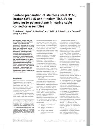
Grit-blasting of different substrates
using Al2O3 grit
To investigate the effect of different
substrates, roughness data were
obtained from stainless steel, bronze
and Ti6Al4V after grit-blasting with
Al2O3 (mesh size 30/40, 624/438 mm)
(Table 6). The Ra of stainless steel and
Ti6Al4V were found to have identical
values (3.71¡0.33 mm (n55) and
3.71¡0.45 mm (n55), respectively,
p.0.05), whereas that for bronze was
higher (4.75¡0.70 mm (n55); p,0.05;
Table 6). Marked variations in particle-
embedment were also observed from
SEM (Fig. 8), where grit-embedment
decreased in the order stainless
steel.bronze.Ti6Al4V. This sequence
is probably related to the hardness
values of these metals (Table 2).
Material hardness is likely to determine
the amount of elastic and/or plastic
deformation cause by an impinging grit
6 Images (SEM) of non-grit-blasted stainless steel
Table 4 Roughness values of grit-blasted stainless steel at different blast
pressures
Grit Sample Pressure/psi Ra/mm Rq/mm Rp/mm Rv/mm
Al2O3 1 40 3.02 3.89 11.59 12.85
Al2O3 2 40 3.42 4.34 13.57 12.75
Al2O3 3 50 3.79 4.79 14.31 13.01
Al2O3 4 50 4.26 5.44 15.16 16.21
Al2O3 5 60 3.97 4.99 13.33 14.67
Al2O3 6 70 4.32 5.53 16.49 16.35
Al2O3 7 80 4.14 5.22 13.28 15.21
Al2O3 8 80 3.92 4.94 14.34 14.43
SiC 1 60 2.04 2.60 7.81 8.33
SiC 2 60 2.07 2.63 7.75 8.32
SiC 3 80 2.69 3.38 8.46 10.11
SiC 4 80 2.58 3.25 9.04 10.30
7 Images (SEM) of stainless steel after grit-blasting with Al2O3 and SiC: a, b
Al2O3 grit-blasted surface showing particle embedment (dark spots) and
shiny particulates (Al2O3) present in craters, respectively; c, d SiC grit-
blasted surface showing reduced particle embedment (dark spots) and a SiC
particle, respectively
B U L L E T I N
Transactions of the Institute of Metal Finishing 2011 VOL 89 NO 5 241
6. particle. Plastic indentation could be
minimal for harder materials,24
hence
reducing the likelihood of grit-
embedment. The hardness of the grit
material could be a contributing factor,
as softer grits will tend to be less
effective on harder metal substrates,
absorbing kinetic energy on impact
causing particle breakage and surface-
embedment.21,24
Ductile tearing in
bronze was also observed, as reported
by Griffiths et al.11
Effect of grit-blasting on polymer-
to-metal adhesion
Bond-strength tests were carried out to
investigate which grit had the greatest
effect on polymer-to-metal adhesion.
Stainless steel samples grit-blasted
with Al2O3 (mesh size 30/40) were
found to have lower (p,0.05) bond
strengths than those produced using
SiC (mesh size 46): (mean¡sd)
30.1¡1.9 kg (n56) and 38.7¡3.1 kg
(n53), respectively. For further
comparison, as-received (machined,
non-grit-blasted) surfaces exhibited
lower (p,0.05) bond strengths of
23.9¡1.7 kg (n53). These results
confirm that grit-blasting enhances the
adhesion of polymer-to-metal bonds, as
reported by Griffith et al.,11
who also
found that grit-embedment caused a
reduction in the adhesion of plasma
coating on steel. Increased bond
strength in grit-blasted samples is
thought to be due to mechanical
interlocking of the polymer into the
surface irregularities of the metal and/
or an increased interfacial area available
for chemical bonding. The type and
morphology of the oxide layer formed
as a consequence of surface pre-
treatment is also said to be a significant
contributor to adhesive bond
strength.41
Conclusions
Stainless steel 316L, bronze CW451K
and Ti6Al4V, used in marine/offshore
metal cable connector assemblies,
have been grit-blasted with Al2O3 and
SiC particles.
1. Al2O3 grit increased the surface
roughness of stainless steel slightly
when the pressure was increased from
40 to 50 psi (276 to 345 kN m22
),
although no further roughening was
observed on increasing the pressure to
80 psi (552 kN m22
).
2. Rougher stainless steel surfaces
were achieved when grit-blasted with
Al2O3 (30/40 mesh size, 635/438 mm)
than SiC (46 mesh size, 370 mm), due to
the smaller size of the SiC grit. When
the same-size grit (36 mesh size,
525 mm) was used, however, no
differences in roughness were
observed.
3. Al2O3-abraded stainless steel
surfaces exhibited substantially larger
amounts of embedded grit particles
than when SiC was used.
4. Identical roughness values were
found for stainless steel and Ti6Al4V
when grit-blasted using Al2O3, whereas
bronze yielded rougher surfaces. Grit-
embedment decreased in the order
stainless steel.bronze.Ti6Al4V, in line
with hardness.
5. Stainless steel grit-blasted with
Al2O3 had lower bond strengths to PU
than when SiC was used, although both
were stronger than non-grit-blasted
substrates. Bond strength was related
to the extent of particle-embedment.
Acknowledgements
This work was funded through a
Knowledge Transfer Partnership (KTP)
programme between PDM Neptec Ltd
and University of Portsmouth, funded
Table 5 Roughness values of stainless steel grit-blasted with same-size grit
material (size 36, 525 mm) at 60 psi (414 kN m22
)
Grit type Sample Ra/mm Rq/mm Rp/mm Rv/mm
Al2O3 1 4.14 5.08 11.23 12.43
Al2O3 2 4.70 5.96 13.00 15.72
Al2O3 3 3.55 4.48 9.18 13.56
Al2O3 4 4.55 6.05 12.44 17.83
SiC 5 3.82 4.92 11.30 13.98
SiC 6 4.35 5.55 12.57 14.09
SiC 7 3.75 4.76 10.19 13.72
SiC 8 3.94 4.90 11.48 12.62
Table 6 Roughness values of different metals grit-blasted with Al2O3 (mesh
size 30/40, 624/438 mm) at 60 psi (414 kN m22
)*
Metal substrate Ra/mm Rq/mm Rp/mm Rv/mm
Stainless steel 3.89 5.03 13.60 17.21
Stainless steel 3.13 4.07 14.80 10.29
Stainless steel 3.82 4.79 13.92 13.9
Stainless steel 3.92 4.92 12.88 18.00
Stainless steel 3.79 4.86 15.07 14.74
mean¡sd 3.71¡0.33 4.73¡0.38 14.05¡0.89 14.83¡3.05
Bronze 5.49 6.88 16.18 21.45
Bronze 3.99 5.03 15.55 12.39
Bronze 4.06 5.25 17.14 14.75
Bronze 4.91 6.38 19.41 18.89
Bronze 5.32 6.60 18.91 18.63
mean¡sd 4.75¡0.70 6.03¡0.83 17.44¡1.68 17.22¡3.61
Ti6Al4V 4.20 5.27 15.24 14.17
Ti6Al4V 3.22 4.11 12.25 11.54
Ti6Al4V 3.32 4.29 13.79 13.43
Ti6Al4V 3.71 4.60 12.76 14.32
Ti6Al4V 4.12 5.19 15.71 15.45
mean¡sd 3.71¡0.45 4.69¡0.52 13.95¡1.51 13.78¡1.45
*Ra of untreated surfaces (mean¡sd): stainless steel, 0.52¡0.09 mm; bronze,
0.22¡0.21 mm; Ti6Al4V, 0.38¡0.02 mm.
a stainless steel; b bronze; c Ti6Al4V
8 Images (SEM) of Al2O3-grit-blasted
surfaces
B U L L E T I N
242 Transactions of the Institute of Metal Finishing 2011 VOL 89 NO 5
7. by the Technology Strategy Board, UK
(Department for Business, Innovation
and Skills, BIS).
References
1. A. V. Bray and S. L. Arnett: ‘Testing
cathodic resistant coatings for
underwater electrical connectors
and marine rubber-to-metal bonds’,
Marine Technol. Soc. Conf. Proc.;
1993, Austin, TX, Texas Research
Institute Austin, Inc.
2. S. L. Arnett, A. V. Bray, J. W.
Bulluck, C. P. Thornton and R. A.
Rushing: ‘Non-conductive coatings
for underwater connector back-
shells’, US patent 5942333, 1999.
3. ‘Molding procedure’, PDM Neptec
Ltd, Alton, Hampshire, UK, 2007.
4. T. Romotowski: ‘Accelerated life test-
ing of marine cables and connectors.
Problems, pitfalls and suggestions
for improvement’, Transducers Ma-
terials Branch NUWC Division
Newport (Code 21320), Newton, RI,
USA, 2002, 512–516.
5. W. Furbeth and M. Stratmann:
Corros. Sci., 2001, 43, (2), 207–227.
6. A. Leng, H. Streckel and M.
Stratmann: Corros. Sci., 1999, 41,
(3), 547–578.
7. H. Leidheiser and W. Wang: J. Coat.
Technol., 1981, 53, (672), 77–84.
8. H. Leidheiser, W. Wang, R. D.
Granata, H. Vedage and M. L.
White: J. Coat. Technol., 1984,
56, (717), 55–56.
9. A. Leng, H. Streckel and M.
Stratmann: Corros. Sci., 1999, 41,
(3), 579–597.
10. J. F. Watts and J. E. Castle: J. Mater.
Sci., 1983, 18, (10), 2987–3003.
11. B. J. Griffiths, D. T. Gawne and
G. S. Dong: Wear, 1996, 194, (1–2),
95–102.
12. A. F. Harris and A. Beevers: Int.
J. Adh. Adhesiv., 1999, 19, (6),
445–452.
13. Z. Mohammadi, A. A. Ziaei-
Moayyed and A. S. M. Mesgar:
J. Mater. Process. Technol., 2007,
194, 15–23.
14. M. H. Staia, E. Ramos, A. Carras-
quero, A. Roman, J. Lesage, D.
Chicot and G. Mesmacque: Thin
Solid Films, 2000, 377, 657–664.
15. E. Celik, A. S. Demirkiran and E.
Avci: Surf. Coat. Technol., 1999,
116, 1061–1064.
16. L. L. Shreir, R. A. Jarman and G. T.
Burstein: ‘Corrosion control 2’, 3rd
edn; 1994, Oxford, Butterworth-
Heinemann Ltd.
17. A. J. Kinloch: ‘Adhesion and adhe-
sives, science and technology’;
1987, London, Chapman and Hall.
18. C. Hall: ‘Polymer materials: an
introduction for technologists and
scientists’, 2nd edn; 1989, New
York, Wiley.
19. S. Amada and T. Hirose: Surf. Coat.
Technol., 1998, 102, (1–2), 132–
137.
20. B. W. Darvell, N. Samman, W. K.
Luk, R. K. F. Clark and H. Tideman:
J. Dent., 1995, 23, (5), 319–322.
21. ‘Painting: new construction and
maintenance’, Manual No. EM1110-
2-3400, US Army Corps of Engi-
neers, Engineering and Design,
Washington DC, USA, 1995.
22. Joint Surface Preparation Standard
NACE No. 2/SSPC-SP 10 Near-White
Metal Blast Cleaning, Item No.
21066., October 1994, Pittsburgh,
PA, USA
23. P. Longstaff: Trans. Inst. Met.
Finish., 2009, 87, (6), 287–289.
24. ‘Blast media guide’, Guyson Int.
Ltd, Skipton, UK, 2007.
25. G. W. Critchlow, R. Litchfield, C.
Curtis and M. Owen: Trans. Inst.
Met. Finish., 2009, 87, (6), 284–
286.
26. G. W. Reade, C. Kerr, B. D. Barker
and F. C. Walsh: Trans. Inst. Met.
Finish., 1998, 76, 149–155.
27. D. T. Gawne, B. J. Griffiths and G.
Dong: Trans. Inst. Met. Finish.,
1997, 75, 205–207.
28. M. Saremi and B. M. Golshan:
Trans. Inst. Met. Finish., 2007, 85,
(2), 99–102.
29. ‘CASTI metals red book – nonferrous
data’, 4th edn; 2003, Edmonton,
Alberta, CASTI Publishing Inc.
30. A to Z of Materials, www.azoms.
com.
31. Z. Makama: ‘Standard method
for surface preparation’, Standard
PDM/STD/3009, PDM Neptec Ltd,
Omega Business Park, Alton,
Hampshire, UK, 2008.
32. ‘Technical drawings – method of
indicating surface texture’, ISO
1302, 1992.
33. ‘Geometric product specifications
(GPS). Indication of surface texture
in technical product documenta-
tion’, ISO 1302, 2002.
34. J. R. Smith, S. Breakspear and
S. A. Campbell: Trans. Inst. Met.
Finish., 2003, 81, B55–B58.
35. M. Faller, S. Buzzi and O. V.
Trzebiatowski: Mater. Corros., 2005,
56, 373–378.
36. C. Honess: ‘Importance of surface
finish in the design of stainless steel’,
Swindon Technology Centre, Corus
RD&T & Alan Harrison, Stainless
Steel Advisory Service, 2006.
37. M. Pegueroles, F. J. Gil, J. A. Planell
and C. Aparicio: Surf. Coat.
Technol., 2008, 202, (15), 3470–
3479.
38. G. Fowler, P. H. Shipway and I. R.
Pashby: J. Mater. Proc. Technol.,
2005, 159, (3), 356–368.
39. K. P. Chander, M. Vashista, K.
Sabiruddin, S. Paul and P. P. Bandy-
opadhyay: Mater. Des., 2009, 30, (8),
2895–2902.
40. The Society of Protective Coatings
(SSPC). Surface Preparation Spe-
cification, Surface Preparation Com-
mentary for Steel and Concrete
Substrates SSPC-SP COM, Pitts-
burgh, PA, USA, 2004, www.sspc.
org.
41. J. D. Venables: J. Mater. Sci.,
1984, 19, (8), 2431–2453.
B U L L E T I N
Transactions of the Institute of Metal Finishing 2011 VOL 89 NO 5 243