Resolução.física sears zemansky 12ª edição young e freedman (todos os volumes) (1) removed
1. 5-1
APPLYING NEWTON’S LAWS
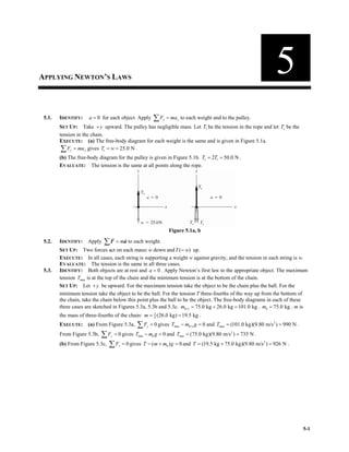
5.1. IDENTIFY: 0
a = for each object. Apply y y
F ma
=
∑ to each weight and to the pulley.
SET UP: Take y
+ upward. The pulley has negligible mass. Let r
T be the tension in the rope and let c
T be the
tension in the chain.
EXECUTE: (a) The free-body diagram for each weight is the same and is given in Figure 5.1a.
y y
F ma
=
∑ gives r 25.0 N
T w
= = .
(b) The free-body diagram for the pulley is given in Figure 5.1b. c r
2 50.0 N
T T
= = .
EVALUATE: The tension is the same at all points along the rope.
Figure 5.1a, b
5.2. IDENTIFY: Apply m
=
∑F a
! !
to each weight.
SET UP: Two forces act on each mass: w down and ( )
T w
= up.
EXECUTE: In all cases, each string is supporting a weight w against gravity, and the tension in each string is w.
EVALUATE: The tension is the same in all three cases.
5.3. IDENTIFY: Both objects are at rest and 0
a = . Apply Newton’s first law to the appropriate object. The maximum
tension max
T is at the top of the chain and the minimum tension is at the bottom of the chain.
SET UP: Let y
+ be upward. For the maximum tension take the object to be the chain plus the ball. For the
minimum tension take the object to be the ball. For the tension T three-fourths of the way up from the bottom of
the chain, take the chain below this point plus the ball to be the object. The free-body diagrams in each of these
three cases are sketched in Figures 5.3a, 5.3b and 5.3c. b+c 75.0 kg 26.0 kg 101.0 kg
m = + = . b 75.0 kg
m = . m is
the mass of three-fourths of the chain: 3
4
(26.0 kg) 19.5 kg
m = = .
EXECUTE: (a) From Figure 5.3a, 0
y
F =
∑ gives max b+c 0
T m g
− = and 2
max (101.0 kg)(9.80 m/s ) 990 N
T = = .
From Figure 5.3b, 0
y
F =
∑ gives min b 0
T m g
− = and 2
min (75.0 kg)(9.80 m/s ) 735 N
T = = .
(b) From Figure 5.3c, 0
y
F =
∑ gives b
( ) 0
T m m g
− + = and 2
(19.5 kg 75.0 kg)(9.80 m/s ) 926 N
T = + = .
5
2. 5-2 Chapter 5
EVALUATE: The tension in the chain increases linearly from the bottom to the top of the chain.
Figure 5.3a–c
5.4. IDENTIFY: Apply Newton’s 1st law to the person. Each half of the rope exerts a force on him, directed along the
rope and equal to the tension T in the rope.
SET UP: (a) The force diagram for the person is given in Figure 5.4
1
T and 2
T are the
tensions in each half of
the rope.
Figure 5.4
EXECUTE: 0
x
F =
∑
2 1
cos cos 0
T T
θ θ
− =
This says that 1 2
T T T
= = (The tension is the same on both sides of the person.)
0
y
F =
∑
1 2
sin sin 0
T T mg
θ θ
+ − =
But 1 2 ,
T T T
= = so 2 sin
T mg
θ =
2
(90.0 kg)(9.80 m/s )
2540 N
2sin 2sin10.0
mg
T
θ
= = =
°
(b) The relation 2 sin
T mg
θ = still applies but now we are given that 4
2.50 10 N
T = × (the breaking strength) and
are asked to find .
θ
2
4
(90.0 kg)(9.80 m/s )
sin 0.01764,
2 2(2.50 10 N)
mg
T
θ = = =
×
1.01 .
θ = °
EVALUATE: /(2sin )
T mg θ
= says that /2
T mg
= when 90
θ = ° (rope is vertical).
T → ∞ when 0
θ → since the upward component of the tension becomes a smaller fraction of the tension.
5.5. IDENTIFY: Apply m
=
∑F a
! !
to the frame.
SET UP: Let w be the weight of the frame. Since the two wires make the same angle with the vertical, the tension
is the same in each wire. 0.75
T w
= .
EXECUTE: The vertical component of the force due to the tension in each wire must be half of the weight, and
this in turn is the tension multiplied by the cosine of the angle each wire makes with the vertical.
3
cos
2 4
w w
θ
=
and 2
3
arccos 48
θ = = ° .
EVALUATE: If 0
θ = ° , /2
T w
= and T → ∞ as 90
θ → ° . Therefore, there must be an angle where 3 /4
T w
= .
3. Applying Newton’s Laws 5-3
5.6. IDENTIFY: Apply Newton’s 1st law to the car. The forces are the same as in Example 5.5.
SET UP: The free-body diagram is sketched in Figure 5.6.
EXECUTE:
x x
F ma
=
∑
cos sin 0
T n
α α
− =
cos sin
T n
α α
=
y y
F ma
=
∑
cos sin 0
n T w
α α
+ − =
cos sin
n T w
α α
+ =
Figure 5.6
The first equation gives
cos
.
sin
n T
α
α
⎛ ⎞
= ⎜ ⎟
⎝ ⎠
Use this in the second equation to eliminate n:
cos
cos sin
sin
T T w
α
α α
α
⎛ ⎞
+ =
⎜ ⎟
⎝ ⎠
Multiply this equation by sin :
α
2 2
(cos sin ) sin
T w
α α α
+ =
sin
T w α
= (since 2 2
cos sin 1
α α
+ = ).
Then
cos cos
sin cos .
sin sin
n T w w
α α
α α
α α
⎛ ⎞ ⎛ ⎞
= = =
⎜ ⎟ ⎜ ⎟
⎝ ⎠ ⎝ ⎠
EVALUATE: These results are the same as obtained in Example 5.5. The choice of coordinate axes is up to us.
Some choices may make the calculation easier, but the results are the same for any choice of axes.
5.7. IDENTIFY: Apply m
=
∑F a
! !
to the car.
SET UP: Use coordinates with x
+ parallel to the surface of the street.
EXECUTE: 0
x
F =
∑ gives sin
T w α
= . 2 3
sin (1390 kg)(9.80 m/s )sin17.5 4.10 10 N
F mg θ
= = ° = × .
EVALUATE: The force required is less than the weight of the car by the factor sinα .
5.8. IDENTIFY: Apply Newton’s 1st law to the wrecking ball. Each cable exerts a force on the ball, directed along the
cable.
SET UP: The force diagram for the wrecking ball is sketched in Figure 5.8.
Figure 5.8
EXECUTE:
(a) y y
F ma
=
∑
cos40 0
B
T mg
° − =
2
4
(4090 kg)(9.80 m/s )
5.23 10 N
cos40 cos40
B
mg
T = = = ×
° °
(b) x x
F ma
=
∑
sin40 0
B A
T T
° − =
4
sin40 3.36 10 N
A B
T T
= ° = ×
EVALUATE: If the angle 40° is replaces by 0° (cable B is vertical), then B
T mg
= and 0.
A
T =
4. 5-4 Chapter 5
5.9. IDENTIFY: Apply m
=
∑F a
! !
to the object and to the knot where the cords are joined.
SET UP: Let y
+ be upward and x
+ be to the right.
EXECUTE: (a) , sin30 sin45 , and cos30 cos45 0.
C A B C A B
T w T T T w T T
= ° + ° = = ° − ° = Since sin45 cos45 ,
° = °
adding the last two equations gives (cos30 sin30 ) ,
A
T w
° + ° = and so 0.732 .
1.366
A
w
T w
= = Then,
cos30
0.897 .
cos45
B A
T T w
°
= =
°
(b) Similar to part (a), , cos60 sin45 ,
C A B
T w T T w
= − ° + ° = and sin60 cos45 0.
A B
T T
° − ° =
Adding these two equations, 2.73 ,
(sin60 cos60 )
A
w
T w
= =
° − °
and
sin60
3.35 .
cos45
B A
T T w
°
= =
°
EVALUATE: In part (a), A B
T T w
+ > since only the vertical components of A
T and B
T hold the object against
gravity. In part (b), since A
T has a downward component B
T is greater than w.
5.10. IDENTIFY: Apply Newton’s first law to the car.
SET UP: Use x and y coordinates that are parallel and perpendicular to the ramp.
EXECUTE: (a) The free-body diagram for the car is given in Figure 5.10. The vertical weight w and the tension T
in the cable have each been replaced by their x and y components.
(b) 0
x
F =
∑ gives cos31.0 sin25.0 0
T w
− =
° ° and 2
sin25.0 sin 25.0
(1130 kg)(9.80 m/s ) 5460 N
cos31.0 cos31.0
T w
= = =
° °
° °
.
(c) 0
y
F =
∑ gives sin31.0 cos25.0 0
n T w
+ − =
° ° and
2
cos25.0 sin31.0 kg 9.80 m/s )cos25.0 (5460 N)sin31.0 7220 N
n w T
= − =
°− ° =(1130 )( ° °
EVALUATE: We could also use coordinates that are horizontal and vertical and would obtain the same values of n
and T.
Figure 5.10
5.11. IDENTIFY: Since the velocity is constant, apply Newton’s first law to the piano. The push applied by the man
must oppose the component of gravity down the incline.
SET UP: The free-body diagrams for the two cases are shown in Figures 5.11a and b. F
!
is the force applied by
the man. Use the coordinates shown in the figure.
EXECUTE: (a) 0
x
F =
∑ gives sin11.0 0
F w
− =
° and 2
(180 kg)(9.80 m/s )sin11.0 337 N
F = ° = .
(b) 0
y
F =
∑ gives cos11.0 0
n w
− =
° and
cos11.0
w
n =
°
. 0
x
F =
∑ gives sin11.0 0
F n
− =
° and
sin11.0 tan11.0 N
cos11.0
w
F w
⎛ ⎞
= ⎜ ⎟
⎝ ⎠
° = ° = 343
°
.
5. 5-6 Chapter 5
(b) Apply 0
x
F =
∑ to the force diagram for the lower knot:
0
x
F =
∑
2 cos45 (84.9 N)cos45 60.0 N
F T
= ° = ° =
SET UP: The free-body diagram for the upper knot is given in Figure 5.12d.
EXECUTE:
0
x
F =
∑
1
cos45 0
T F
° − =
1 (84.9 N)cos45
F = °
1 60.0 N
F =
Figure 5.12d
Note that 1 2.
F F
=
EVALUATE: Applying 0
y
F =
∑ to the upper knot gives sin45 60.0 N .
T T w
′′ = ° = = If we treat the whole
system as a single object, the force diagram is given in Figure 5.12e.
0
x
F =
∑ gives 2 1,
F F
= which checks
0
y
F =
∑ gives ,
T w
′′ = which checks
Figure 5.12e
5.13. IDENTIFY: Apply Newton’s first law to the ball. The force of the wall on the ball and the force of the ball on the
wall are related by Newton’s third law.
SET UP: The forces on the ball are its weight, the tension in the wire, and the normal force applied by the wall.
To calculate the angle φ that the wire makes with the wall, use Figure 5.13a.
16.0 cm
sin
46.0 cm
φ = and 20.35
φ = °
EXECUTE: (a) The free-body diagram is shown in Figure 5.13b. Use the x and y coordinates shown in the figure.
0
y
F =
∑ gives cos 0
T w
φ − = and
2
(45.0 kg)(9.80 m/s )
470 N
cos cos20.35
w
T
φ
= = =
°
(b) 0
x
F =
∑ gives sin 0
T n
φ − = . (470 N)sin20.35 163 N
n = =
° . By Newton’s third law, the force the ball
exerts on the wall is 163 N, directed to the right.
EVALUATE: sin tan
cos
w
n w
φ φ
φ
⎛ ⎞
= =
⎜ ⎟
⎝ ⎠
. As the angle φ decreases (by increasing the length of the wire), T
decreases and n decreases.
Figure 5.13a, b
5.14. IDENTIFY: Apply m
=
∑F a
! !
to each block. 0
a = .
SET UP: Take y
+ perpendicular to the incline and x
+ parallel to the incline.
6. Applying Newton’s Laws 5-7
EXECUTE: The free-body diagrams for each block, A and B, are given in Figure 5.14.
(a) For B, x x
F ma
=
∑ gives 1 sin 0
T w α
− = and 1 sin
T w α
= .
(b) For block A, x x
F ma
=
∑ gives 1 2 sin 0
T T w α
− − = and 2 2 sin
T w α
= .
(c) y y
F ma
=
∑ for each block gives cos
A B
n n w α
= = .
(d) For 0
α → , 1 2 0
T T
= → and A B
n n w
= → . For 90
α → ° , 1
T w
= , 2 2
T w
= and 0
A B
n n
= = .
EVALUATE: The two tensions are different but the two normal forces are the same.
Figure 5.14a, b
5.15. IDENTIFY: Apply Newton’s first law to the ball. Treat the ball as a particle.
SET UP: The forces on the ball are gravity, the tension in the wire and the normal force exerted by the surface.
The normal force is perpendicular to the surface of the ramp. Use x and y axes that are horizontal and vertical.
EXECUTE: (a) The free-body diagram for the ball is given in Figure 5.15. The normal force has been replaced by
its x and y components.
(b) 0
y
F =
∑ gives cos35.0 0
n w
− =
° and 1.22
cos35.0
mg
n mg
= =
°
.
(c) 0
x
F =
∑ gives sin35.0 0
T n
− =
° and (1.22 )sin35.0 0.700
T mg mg
= =
° .
EVALUATE: Note that the normal force is greater than the weight, and increases without limit as the angle of the
ramp increases towards 90° . The tension in the wire is tan
w φ , where φ is the angle of the ramp and T also
increases without limit as 90
φ → ° .
Figure 5.15
5.16. IDENTIFY: Apply Newton’s second law to the rocket plus its contents and to the power supply. Both the rocket
and the power supply have the same acceleration.
SET UP: The free-body diagrams for the rocket and for the power supply are given in Figures 5.16a and b. Since
the highest altitude of the rocket is 120 m, it is near to the surface of the earth and there is a downward gravity
force on each object. Let y
+ be upward, since that is the direction of the acceleration. The power supply has
mass 2
ps (15.5 N)/(9.80 m/s ) 1.58 kg
m = =
7. 5-8 Chapter 5
EXECUTE: (a) y y
F ma
=
∑ applied to the rocket gives r r
F m g m a
− = .
2
2
r
r
1720 N (125 kg)(9.80 m/s )
3.96 m/s
125 kg
F m g
a
m
− −
= = = .
(b) y y
F ma
=
∑ applied to the power supply gives ps ps
n m g m a
− = .
2 2
ps ( ) (1.58 kg)(9.80 m/s 3.96 m/s ) 21.7 N
n m g a
= + = + = .
EVALUATE: The acceleration is constant while the thrust is constant and the normal force is constant while the
acceleration is constant. The altitude of 120 m is not used in the calculation.
Figure 5.16a, b
5.17. IDENTIFY: Use the kinematic information to find the acceleration of the capsule and the stopping time. Use
Newton’s second law to find the force F that the ground exerted on the capsule during the crash.
SET UP: Let y
+ be upward. 311 km/h 86.4 m/s
= . The free-body diagram for the capsule is given in
Figure 15.17.
EXECUTE: 0 0.810 m
y y
− = − , 0 86.4 m/s
y
v = − , 0
y
v = . 2 2
0 0
2 ( )
y y y
v v a y y
= + − gives
2 2 2
0 2
0
0 ( 86.4 m/s)
4610 m/s 470
2( ) 2( 0.810) m
y y
y
v v
a g
y y
− − −
= = = =
− −
.
(b) y y
F ma
=
∑ applied to the capsule gives F mg ma
− = and
2 2 5
( ) (210 kg)(9.80 m/s 4610 m/s ) 9.70 10 N 471 .
F m g a w
= + = + = × =
(c) 0
0
2
y y
v v
y y t
+
⎛ ⎞
− = ⎜ ⎟
⎝ ⎠
gives 0
2
0
2( ) 2( 0.810 m)
0.0187 s
86.4 m/s 0
y y
y y
t
v v
− −
= = =
+ − +
EVALUATE: The upward force exerted by the ground is much larger than the weight of the capsule and stops the
capsule in a short amount of time. After the capsule has come to rest, the ground still exerts a force mg on the
capsule, but the large 5
9.00 10 N
× force is exerted only for 0.0187 s.
Figure 5.17
5.18. IDENTIFY: Apply Newton’s second law to the three sleds taken together as a composite object and to each
individual sled. All three sleds have the same horizontal acceleration a.
SET UP: The free-body diagram for the three sleds taken as a composite object is given in Figure 5.18a and for
each individual sled in Figure 5.18b-d. Let x
+ be to the right, in the direction of the acceleration. tot 60.0 kg
m = .
EXECUTE: (a) x x
F ma
=
∑ for the three sleds as a composite object gives tot
P m a
= and
2
tot
125 N
2.08 m/s
60.0 kg
P
a
m
= = = .
8. Applying Newton’s Laws 5-9
(b) x x
F ma
=
∑ applied to the 10.0 kg sled gives 10
A
P T m a
− = and
2
10 125 N (10.0 kg)(2.08 m/s ) 104 N
A
T P m a
= − = − = . x x
F ma
=
∑ applied to the 30.0 kg sled gives
2
30 (30.0 kg)(2.08 m/s ) 62.4 N
B
T m a
= = = .
EVALUATE: If we apply x x
F ma
=
∑ to the 20.0 kg sled and calculate a from A
T and B
T found in part (b), we get
20
A B
T T m a
− = . 2
20
104 N 62.4 N
2.08 m/s
20.0 kg
A B
T T
a
m
− −
= = = , which agrees with the value we calculated in part (a).
Figure 5.18a–d
5.19. IDENTIFY: Apply m
=
∑F a
! !
to the load of bricks and to the counterweight. The tension is the same at each end
of the rope. The rope pulls up with the same force ( )
T on the bricks and on the counterweight. The counterweight
accelerates downward and the bricks accelerate upward; these accelerations have the same magnitude.
(a) SET UP: The free-body diagrams for the bricks and counterweight are given in Figure 5.19.
Figure 5.19
(b) EXECUTE: Apply y y
F ma
=
∑ to each object. The acceleration magnitude is the same for the two objects.
For the bricks take y
+ to be upward since a
!
for the bricks is upward. For the counterweight take y
+ to be
downward since a
!
is downward.
bricks: y y
F ma
=
∑
1 1
T m g m a
− =
counterweight: y y
F ma
=
∑
2 2
m g T m a
− =
Add these two equations to eliminate T:
2 1 1 2
( ) ( )
m m g m m a
− = +
2 2
2 1
1 2
28.0 kg 15.0 kg
(9.80 m/s ) 2.96 m/s
15.0 kg 28.0 kg
m m
a g
m m
⎛ ⎞ ⎛ ⎞
− −
= = =
⎜ ⎟ ⎜ ⎟
+ +
⎝ ⎠
⎝ ⎠
(c) 1 1
T m g m a
− = gives 2 2
1( ) (15.0 kg)(2.96 m/s 9.80 m/s ) 191 N
T m a g
= + = + =
As a check, calculate T using the other equation.
2 2
m g T m a
− = gives 2 2
2 ( ) 28.0 kg(9.80 m/s 2.96 m/s ) 191 N,
T m g a
= − = − = which checks.
9. 5-10 Chapter 5
EVALUATE: The tension is 1.30 times the weight of the bricks; this causes the bricks to accelerate upward. The
tension is 0.696 times the weight of the counterweight; this causes the counterweight to accelerate downward. If
1 2,
m m
= 0
a = and 1 2 .
T m g m g
= = In this special case the objects don’t move. If 1 0,
m = a g
= and 0;
T = in
this special case the counterweight is in free-fall. Our general result is correct in these two special cases.
5.20. IDENTIFY: In part (a) use the kinematic information and the constant acceleration equations to calculate the
acceleration of the ice. Then apply m
∑F = a
! !
. In part (b) use m
∑F = a
! !
to find the acceleration and use this in
the constant acceleration equations to find the final speed.
SET UP: Figures 5.20a and b give the free-body diagrams for the ice both with and without friction. Let x
+ be
directed down the ramp, so y
+ is perpendicular to the ramp surface. Let φ be the angle between the ramp and the
horizontal. The gravity force has been replaced by its x and y components.
EXECUTE: (a) 0 1.50 m
x x
− = , 0 0
x
v = , 2.50 m/s
x
v = . 2 2
0 0
2 ( )
x x x
v v a x x
= + − gives
2 2 2
2
0
0
(2.50 m/s) 0
2.08 m/s
2( ) 2(1.50 m)
x x
x
v v
a
x x
− −
= = =
−
. x x
F ma
=
∑ gives sin
mg ma
φ = and
2
2
2.08 m/s
sin
9.80 m/s
a
g
φ = = .
12.3
φ = ° .
(b) x x
F ma
=
∑ gives sin
mg f ma
φ − = and
2
2
sin (8.00 kg)(9.80 m/s )sin12.3 10.0 N
0.838 m/s
8.00 kg
mg f
a
m
φ − −
= = =
°
.
Then 0 1.50 m
x x
− = , 0 0
x
v = , 2
0.838 m/s
x
a = and 2 2
0 0
2 ( )
x x x
v v a x x
= + − gives
2
0
2 ( ) 2(0.838 m/s )(1.50 m) 1.59 m/s
x x
v a x x
= − = =
EVALUATE: With friction present the speed at the bottom of the ramp is less.
Figure 5.20a, b
5.21. IDENTIFY: Apply m
∑F = a
! !
to each block. Each block has the same magnitude of acceleration a.
SET UP: Assume the pulley is to the right of the 4.00 kg block. There is no friction force on the 4.00 kg block,
the only force on it is the tension in the rope. The 4.00 kg block therefore accelerates to the right and the suspended
block accelerates downward. Let x
+ be to the right for the 4.00 kg block, so for it x
a a
= , and let y
+ be
downward for the suspended block, so for it y
a a
= .
EXECUTE: (a) The free-body diagrams for each block are given in Figures 5.21a and b.
(b) x x
F ma
=
∑ applied to the 4.00 kg block gives (4.00 kg)
T a
= and 2
10.0 N
2.50 m/s
4.00 kg 4.00 kg
T
a = = = .
(c) y y
F ma
=
∑ applied to the suspended block gives mg T ma
− = and
2 2
10.0 N
1.37 kg
9.80 m/s 2.50 m/s
T
m
g a
= = =
− −
.
(d) The weight of the hanging block is 2
(1.37 kg)(9.80 m/s ) 13.4 N
mg = = . This is greater than the tension in the
rope; 0.75
T mg
= .
10. Applying Newton’s Laws 5-11
EVALUATE: Since the hanging block accelerates downward, the net force on this block must be downward and
the weight of the hanging block must be greater than the tension in the rope. Note that the blocks accelerate no
matter how small m is. It is not necessary to have 4.00 kg
m > , and in fact in this problem m is less than 4.00 kg.
Figure 5.21a, b
5.22. IDENTIFY: (a) Consider both gliders together as a single object, apply m
=
∑F a
! !
, and solve for a. Use a in a
constant acceleration equation to find the required runway length.
(b) Apply m
=
∑F a
! !
to the second glider and solve for the tension g
T in the towrope that connects the two
gliders.
SET UP: In part (a), set the tension t
T in the towrope between the plane and the first glider equal to its maximum
value, t 12,000 N
T = .
EXECUTE: (a) The free-body diagram for both gliders as a single object of mass 2 1400 kg
m = is given in Figure
5.22a. x x
F ma
=
∑ gives t 2 (2 )
T f m a
− = and 2
t 2 12,000 N 5000 N
5.00 m/s
2 1400 kg
T f
a
m
− −
= = = . Then
2
5.00 m/s
x
a = , 0 0
x
v = and 40 m/s
x
v = in 2 2
0 0
2 ( )
x x x
v v a x x
= + − gives
2 2
0
0
( ) 160 m
2
x x
x
v v
x x
a
−
− = = .
(b) The free-body diagram for the second glider is given in Figure 5.22b.
x x
F ma
=
∑ gives g
T f ma
− = and 2
2500 N + (700 kg)(5.00 m/s ) 6000 N
T f ma
= + = = .
EVALUATE: We can verify that x x
F ma
=
∑ is also satisfied for the first glider.
Figure 5.22a, b
5.23. IDENTIFY: The maximum tension in the chain is at the top of the chain. Apply m
∑F = a
! !
to the composite
object of chain and boulder. Use the constant acceleration kinematic equations to relate the acceleration to the time.
SET UP: Let y
+ be upward. The free-body diagram for the composite object is given in Figure 5.23.
chain
2.50
T w
= . tot chain boulder 1325 kg
m m m
= + = .
EXECUTE: (a) y y
F ma
=
∑ gives tot tot
T m g m a
− = . tot chain tot chain
tot tot tot
2.50 2.50
1
T m g m g m g m
a g
m m m
⎛ ⎞
− −
= = = −
⎜ ⎟
⎝ ⎠
2 2
2.50[575 kg]
1 (9.80 m/s ) 0.832 m/s
1325 kg
a
⎛ ⎞
= − =
⎜ ⎟
⎝ ⎠
.
11. 5-12 Chapter 5
(b) Assume the acceleration has its maximum value: 2
0.832 m/s
y
a = , 0 125 m
y y
− = and 0 0
y
v = .
2
1
0 0 2
y y
y y v t a t
− = + gives 0
2
2( ) 2(125 m)
17.3 s
0.832 m/s
y
y y
t
a
−
= = =
EVALUATE: The tension in the chain is 4
1.41 10 N
T = × and the total weight is 4
1.30 10 N
× . The upward force
exceeds the downward force and the acceleration is upward.
Figure 5.23
5.24. IDENTIFY: Apply m
∑F = a
! !
to the composite object of elevator plus student ( tot 850 kg
m = ) and also to the
student ( 550 N
w = ). The elevator and the student have the same acceleration.
SET UP: Let y
+ be upward. The free-body diagrams for the composite object and for the student are given in
Figure 5.24a and b. T is the tension in the cable and n is the scale reading, the normal force the scale exerts on the
student. The mass of the student is / 56.1 kg
m w g
= = .
EXECUTE: (a) y y
F ma
=
∑ applied to the student gives y
n mg ma
− = .
2
450 N 550 N
1.78 m/s
56.1 kg
y
n mg
a
m
− −
= = = − . The elevator has a downward acceleration of 2
1.78 m/s .
(b) 2
670 N 550 N
2.14 m/s
56.1 kg
y
a
−
= = .
(c) 0
n = means y
a g
= − . The student should worry; the elevator is in free-fall.
(d) y y
F ma
=
∑ applied to the composite object gives tot tot
T m g m a
− = . tot ( )
y
T m a g
= + . In part (a),
2 2
(850 kg)( 1.78 m/s 9.80 m/s ) 6820 N
T = − + = . In part (c), y
a g
= − and 0
T = .
EVALUATE: In part (b), 2 2
(850 kg)(2.14 m/s 9.80 m/s ) 10,150 N
T = + = . The weight of the composite object is
8330 N. When the acceleration is upward the tension is greater than the weight and when the acceleration is
downward the tension is less than the weight.
Figure 5.24a, b
5.25. IDENTIFY: Apply m
=
∑F a
! !
to the puck. Use the information about the motion to calculate the acceleration. The
table must slope downward to the right.
SET UP: Let α be the angle between the table surface and the horizontal. Let the x
+ -axis be to the right and
parallel to the surface of the table.
EXECUTE: x x
F ma
=
∑ gives sin x
mg ma
α = . The time of travel for the puck is 0
/
L v , where 1.75 m
L = and
0 3.80 m/s
v = . 2
1
0 0 2
x x
x x v t a t
− = + gives
2
0
2 2
2 2
x
x xv
a
t L
= = , where 0.0250 m
x = .
2
0
2
2
sin x
a xv
g gL
α = = .
( )
2 2
2 2
2(2.50 10 m)(3.80 m/s)
arcsin 1.38
9.80 m/s (1.75 m)
α
−
⎛ ⎞
×
⎜ ⎟
= = °
⎜ ⎟
⎝ ⎠
.
12. 5-14 Chapter 5
5.29. (a) IDENTIFY: Constant speed implies 0.
a = Apply Newton’s 1st law to the box. The friction force is directed
opposite to the motion of the box.
SET UP: Consider the free-body diagram for the box, given in Figure 5.29a. Let F
!
be the horizontal force
applied by the worker. The friction is kinetic friction since the box is sliding along the surface.
EXECUTE:
y y
F ma
=
∑
0
n mg
− =
n mg
=
So k k k
f n mg
μ μ
= =
Figure 5.29a
x x
F ma
=
∑
k 0
F f
− =
2
k k (0.20)(11.2 kg)(9.80 m/s ) 22 N
F f mg
μ
= = = =
(b) IDENTIFY: Now the only horizontal force on the box is the kinetic friction force. Apply Newton’s 2nd law to
the box to calculate its acceleration. Once we have the acceleration, we can find the distance using a constant
acceleration equation. The friction force is k k ,
f mg
μ
= just as in part (a).
SET UP: The free-body diagram is sketched in Figure 5.29b.
EXECUTE:
x x
F ma
=
∑
k x
f ma
− =
k x
mg ma
μ
− =
2 2
k (0.20)(9.80 m/s ) 1.96 m/s
x
a g
μ
= − = − = −
Figure 5.29b
Use the constant acceleration equations to find the distance the box travels:
0,
x
v = 0 3.50 m/s,
x
v = 2
1.96 m/s ,
x
a = − 0 ?
x x
− =
2 2
0 0
2 ( )
x x x
v v a x x
= + −
2 2 2
0
0 2
0 (3.50 m/s)
3.1 m
2 2( 1.96 m/s )
x x
x
v v
x x
a
− −
− = = =
−
EVALUATE: The normal force is the component of force exerted by a surface perpendicular to the surface. Its
magnitude is determined by .
m
=
∑F a
! !
In this case n and mg are the only vertical forces and 0,
y
a = so .
n mg
=
Also note that k
f and n are proportional in magnitude but perpendicular in direction.
5.30. IDENTIFY: Apply m
=
∑F a
! !
to the box.
SET UP: Since the only vertical forces are n and w, the normal force on the box equals its weight. Static friction
is as large as it needs to be to prevent relative motion between the box and the surface, up to its maximum possible
value of max
s s
f n
μ
= . If the box is sliding then the friction force is k k
f n
μ
= .
EXECUTE: (a) If there is no applied force, no friction force is needed to keep the box at rest.
(b) max
s s (0.40)(40.0 N) 16.0 N
f n
μ
= = = . If a horizontal force of 6.0 N is applied to the box, then s 6.0 N
f = in
the opposite direction.
(c) The monkey must apply a force equal to max
s
f , 16.0 N.
(d) Once the box has started moving, a force equal to k k 8.0 N
f n
μ
= = is required to keep it moving at constant
velocity.
EVALUATE: k s
μ μ
< and less force must be applied to the box to maintain its motion than to start it moving.
13. Applying Newton’s Laws 5-15
5.31. IDENTIFY: Apply m
∑F = a
! !
to the crate. s s
f n
μ
≤ and k k
f n
μ
= .
SET UP: Let y
+ be upward and let x
+ be in the direction of the push. Since the floor is horizontal and the push
is horizontal, the normal force equals the weight of the crate: 441 N
n mg
= = . The force it takes to start the crate
moving equals s
max f and the force required to keep it moving equals k
f
EXECUTE: s
max 313 N
f = , so s
313 N
0.710
441 N
μ = = . k 208 N
f = , so k
208 N
0.472
441 N
μ = = .
(b) The friction is kinetic. x x
F ma
=
∑ gives k
F f ma
− = and 2
k 208 (45.0 kg)(1.10 m/s ) 258 N
F f ma
= + = + = .
(c) (i) The normal force now is 72.9 N
mg = . To cause it to move, s s
max (0.710)(72.9 N) 51.8 N
F f n
μ
= = = = .
(ii) k
F f ma
= + and 2
k 258 N (0.472)(72.9 N)
4.97 m/s
45.0 kg
F f
a
m
− −
= = =
EVALUATE: The kinetic friction force is independent of the speed of the object. On the moon, the mass of the
crate is the same as on earth, but the weight and normal force are less.
5.32. IDENTIFY: Apply m
=
∑F a
! !
to the box and calculate the normal and friction forces. The coefficient of kinetic
friction is the ratio k
f
n
.
SET UP: Let x
+ be in the direction of motion. 2
0.90 m/s
x
a = − . The box has mass 8.67 kg.
EXECUTE: The normal force has magnitude 85 N 25 N 110 N.
+ = The friction force, from H k
F f ma
− = is
2
k H 20 N (8.67 kg)( 0.90 m/s ) 28 N
f F ma
= − = − − = . k
28 N
0.25.
110 N
μ = =
EVALUATE: The normal force is greater than the weight of the box, because of the downward component of the
push force.
5.33. IDENTIFY: Apply m
∑F = a
! !
to the composite object consisting of the two boxes and to the top box. The friction
the ramp exerts on the lower box is kinetic friction. The upper box doesn’t slip relative to the lower box, so the
friction between the two boxes is static. Since the speed is constant the acceleration is zero.
SET UP: Let x
+ be up the incline. The free-body diagrams for the composite object and for the upper box are
given in Figures 5.33a and b. The slope angle φ of the ramp is given by
2.50 m
tan
4.75 m
φ = , so 27.76
φ = ° . Since the
boxes move down the ramp, the kinetic friction force exerted on the lower box by the ramp is directed up the
incline. To prevent slipping relative to the lower box the static friction force on the upper box is directed up the
incline. tot 32.0 kg 48.0 kg 80.0 kg
m = + = .
EXECUTE: (a) y y
F ma
=
∑ applied to the composite object gives tot tot cos
n m g φ
= and k k tot cos
f m g
μ φ
= .
x x
F ma
=
∑ gives k tot sin 0
f T m g φ
+ − = and
2
k tot
(sin cos ) (sin27.76 [0.444]cos27.76 )(80.0 kg)(9.80 m/s ) 57.1 N
T m g
φ μ φ
= − = − =
° ° .
The person must apply a force of 57.1 N, directed up the ramp.
(b) x x
F ma
=
∑ applied to the upper box gives 2
s sin (32.0 kg)(9.80 m/s )sin27.76 146 N
f mg φ
= = =
° , directed up
the ramp.
EVALUATE: For each object the net force is zero.
Figure 5.33a, b
14. 5-16 Chapter 5
5.34. IDENTIFY: Use m
=
∑F a
! !
to find the acceleration that can be given to the car by the kinetic friction force. Then
use a constant acceleration equation.
SET UP: Take x
+ in the direction the car is moving.
EXECUTE: (a) The free-body diagram for the car is shown in Figure 5.34. y y
F ma
=
∑ gives n mg
= .
x x
F ma
=
∑ gives k x
n ma
μ
− = . k x
mg ma
μ
− = and k
x
a g
μ
= − . Then 0
x
v = and 2 2
0 0
2 ( )
x x x
v v a x x
= + − gives
2 2 2
0 0
0 2
k
(29.1 m/s)
( ) 54.0 m
2 2 2(0.80)(9.80 m/s )
x x
x
v v
x x
a g
μ
− = − = + = = .
(b) 2
0 k 0
2 ( ) 2(0.25)(9.80 m/s )(54.0 m) 16.3 m/s
x
v g x x
μ
= − = =
EVALUATE: For constant stopping distance
2
0
k
x
v
μ
is constant and 0x
v is proportional to k
μ . The answer to
part (b) can be calculated as (29.1 m/s) 0.25/0.80 16.3 m/s
= .
Figure 5.34
5.35. IDENTIFY: For a given initial speed, the distance traveled is inversely proportional to the coefficient of kinetic
friction.
SET UP: From Table 5.1 the coefficient of kinetic friction is 0.04 for Teflon on steel and 0.44 for brass on steel.
EXECUTE: The ratio of the distances is
0.44
11
0.04
= .
EVALUATE: The smaller the coefficient of kinetic friction the smaller the retarding force of friction, and the
greater the stopping distance.
5.36. IDENTIFY: Constant speed means zero acceleration for each block. If the block is moving the friction force the
tabletop exerts on it is kinetic friction. Apply m
∑F = a
! !
to each block.
SET UP: The free-body diagrams and choice of coordinates for each block are given by Figure 5.36.
4.59 kg
A
m = and 2.55 kg
B
m = .
EXECUTE: (a) y y
F ma
=
∑ with 0
y
a = applied to block B gives 0
B
m g T
− = and 25.0 N
T = . x x
F ma
=
∑ with
0
x
a = applied to block A gives k 0
T f
− = and k 25.0 N
f = . 45.0 N
A A
n m g
= = and k
k
25.0 N
0.556
45.0 N
A
f
n
μ = = = .
(b) Now let A be block A plus the cat, so 9.18 kg
A
m = . 90.0 N
A
n = and k k (0.556)(90.0 N) 50.0 N
f n
μ
= = = .
x x
F ma
=
∑ for A gives k A x
T f m a
− = . y y
F ma
=
∑ for block B gives B B y
m g T m a
− = . x
a for A equals y
a for B,
so adding the two equations gives k ( )
B A B y
m g f m m a
− = + and 2
k 25.0 N 50.0 N
2.13 m/s
9.18 kg 2.55 kg
B
y
A B
m g f
a
m m
− −
= = = −
+ +
.
The acceleration is upward and block B slows down.
15. Applying Newton’s Laws 5-17
EVALUATE: The equation k ( )
B A B y
m g f m m a
− = + has a simple interpretation. If both blocks are considered
together then there are two external forces: B
m g that acts to move the system one way and k
f that acts oppositely.
The net force of k
B
m g f
− must accelerate a total mass of A B
m m
+ .
Figure 5.36
5.37. IDENTIFY: Apply m
=
∑F a
! !
to each crate. The rope exerts force T to the right on crate A and force T to the left
on crate B. The target variables are the forces T and F. Constant v implies 0.
a =
SET UP: The free-body diagram for A is sketched in Figure 5.37a
EXECUTE:
y y
F ma
=
∑
0
A A
n m g
− =
A A
n m g
=
k k k
A A A
f n m g
μ μ
= =
Figure 5.37a
x x
F ma
=
∑
k 0
A
T f
− =
k A
T m g
μ
=
SET UP: The free-body diagram for B is sketched in Figure 5.37b.
EXECUTE:
y y
F ma
=
∑
0
B B
n m g
− =
B B
n m g
=
k k k
B B B
f n m g
μ μ
= =
Figure 5.37b
x x
F ma
=
∑
k 0
B
F T f
− − =
k B
F T m g
μ
= +
Use the first equation to replace T in the second:
k k .
A B
F m g m g
μ μ
= +
(a) k ( )
A B
F m m g
μ
= +
(b) k A
T m g
μ
=
EVALUATE: We can also consider both crates together as a single object of mass ( ).
A B
m m
+ x x
F ma
=
∑ for
this combined object gives k k ( ) ,
A B
F f m m g
μ
= = + in agreement with our answer in part (a).
16. 5-22 Chapter 5
EVALUATE: The maximum speed is less for the vertical circle. At the bottom of the vertical path F
!
and the
weight are in opposite directions so F must exceed rad
ma by an amount equal to mg. At the top of the vertical path
F and mg are in the same direction and together provide the required net force, so F must be larger at the bottom.
Figure 5.49
5.50. IDENTIFY: Since the car travels in an arc of a circle, it has acceleration 2
rad /
a v R
= , directed toward the center of
the arc. The only horizontal force on the car is the static friction force exerted by the roadway. To calculate the
minimum coefficient of friction that is required, set the static friction force equal to its maximum value, s s
f n
μ
= .
Friction is static friction because the car is not sliding in the radial direction.
SET UP: The free-body diagram for the car is given in Figure 5.50. The diagram assumes the center of the curve
is to the left of the car.
EXECUTE: (a) y y
F ma
=
∑ gives n mg
= . x x
F ma
=
∑ gives
2
s
v
n m
R
μ = .
2
s
v
mg m
R
μ = and
2 2
s 2
(25.0 m/s)
0.290
(9.80 m/s )(220 m)
v
gR
μ = = =
(b)
2
s
constant
v
Rg
μ
= = , so
2 2
1 2
s1 s2
v v
μ μ
= . s2 s1
2 1
s1 s1
/3
(25.0 m/s) 14.4 m/s
v v
μ μ
μ μ
= = = .
EVALUATE: A smaller coefficient of friction means a smaller maximum friction force, a smaller possible
acceleration and therefore a smaller speed.
Figure 5.50
5.51. IDENTIFY: We can use the analysis done in Example 5.23. As in that example, we assume friction is negligible.
SET UP: From Example 5.23, the banking angle β is given by
2
tan
v
gR
β = . Also, /cos
n mg β
= .
65.0 mi/h 29.1 m/s
= .
EXECUTE: (a)
2
2
(29.1 m/s)
tan
(9.80 m/s )(225 m)
β = and 21.0
β = ° . The expression for tan β does not involve the mass
of the vehicle, so the truck and car should travel at the same speed.
(b) For the car,
2
4
car
(1125 kg)(9.80 m/s )
1.18 10 N
cos21.0
n = = ×
°
and 4
truck car
2 2.36 10 N
n n
= = × , since truck car
2
m m
= .
EVALUATE: The vertical component of the normal force must equal the weight of the vehicle, so the normal
force is proportional to m.
5.52. IDENTIFY: The acceleration of the person is 2
rad /
a v R
= , directed horizontally to the left in the figure in the
problem. The time for one revolution is the period
2 R
T
v
π
= . Apply m
=
∑F a
! !
to the person.
17. Applying Newton’s Laws 5-23
SET UP: The person moves in a circle of radius 3.00 m (5.00 m)sin30.0 5.50 m
R = + =
° . The free-body diagram
is given in Figure 5.52. F
!
is the force applied to the seat by the rod.
EXECUTE: (a) y y
F ma
=
∑ gives cos30.0
F mg
=
° and
cos30.0
mg
F =
°
. x x
F ma
=
∑ gives
2
sin30.0
v
F m
R
=
° .
Combining these two equations gives 2
tan (5.50 m)(9.80 m/s )tan30.0 5.58 m/s
v Rg θ
= = =
° . Then the period
is
2 2 (5.50 m)
6.19 s
5.58 m/s
R
T
v
π π
= = = .
(b) The net force is proportional to m so in m
=
∑F a
! !
the mass divides out and the angle for a given rate of
rotation is independent of the mass of the passengers.
EVALUATE: The person moves in a horizontal circle so the acceleration is horizontal. The net inward force
required for circular motion is produced by a component of the force exerted on the seat by the rod.
Figure 5.52
5.53. IDENTIFY: Apply m
∑F = a
! !
to the composite object of the person plus seat. This object moves in a horizontal
circle and has acceleration rad
a , directed toward the center of the circle.
SET UP: The free-body diagram for the composite object is given in Figure 5.53. Let x
+ be to the right, in the
direction of rad
a
!
. Let y
+ be upward. The radius of the circular path is 7.50 m
R = . The total mass is
2
(255 N 825 N)/(9.80 m/s ) 110.2 kg
+ = . Since the rotation rate is 32.0 rev/min 0.5333 rev/s
= , the period T is
1
1.875 s
0.5333 rev/s
= .
EXECUTE: y y
F ma
=
∑ gives cos40.0 0
A
T mg
− =
° and
255 N 825 N
1410 N
cos40.0 cos40.0
A
mg
T
+
= = =
° °
.
x x
F ma
=
∑ gives rad
sin40.0
A B
T T ma
+ =
° and
2 2
2 2
4 4 (7.50 m)
sin40.0 (110.2 kg) (1410 N)sin40.0 8370 N
(1.875 s)
B A
R
T m T
T
π π
= − = − =
° ° .
The tension in the horizontal cable is 8370 N and the tension in the other cable is 1410 N.
EVALUATE: The weight of the composite object is 1080 N. The tension in cable A is larger than this since its
vertical component must equal the weight. rad 9280 N
ma = . The tension in cable B is less than this because part of
the required inward force comes from a component of the tension in cable A.
Figure 5.53
18. Applying Newton’s Laws 5-27
EVALUATE: The acceleration is upward, so the net force is upward and the tension is greater than the weight.
Figure 5.60
5.61. IDENTIFY: Apply m
∑F = a
! !
to the knot.
SET UP: 0
a = . Use coordinates with axes that are horizontal and vertical.
EXECUTE: (a) The free-body diagram for the knot is sketched in Figure 5.61.
1
T is more vertical so supports more of the weight and is larger. You can also see this from :
x x
F ma
∑ =
2 1
cos40 cos60 0
T T
° − ° = . 2 1
cos40 cos60 0
T T
° − ° = .
(b) 1
T is larger so set 1 5000 N.
T = Then 2 1 1.532 3263.5 N
T T
= = . y y
F ma
∑ = gives
1 2
sin60 sin40
T T w
° + ° = and 6400 N
w = .
EVALUATE: The sum of the vertical components of the two tensions equals the weight of the suspended object.
The sum of the tensions is greater than the weight.
Figure 5.61
5.62. IDENTIFY: Apply m
∑F = a
! !
to each object . Constant speed means 0
a = .
SET UP: The free-body diagrams are sketched in Figure 5.62. 1
T is the tension in the lower chain, 2
T is the
tension in the upper chain and T F
= is the tension in the rope.
EXECUTE: The tension in the lower chain balances the weight and so is equal to w. The lower pulley must have
no net force on it, so twice the tension in the rope must be equal to w and the tension in the rope, which equals F, is
2
w . Then, the downward force on the upper pulley due to the rope is also w, and so the upper chain exerts a force
w on the upper pulley, and the tension in the upper chain is also w.
EVALUATE: The pulley combination allows the worker to lift a weight w by applying a force of only /2
w .
Figure 5.62
5.63. IDENTIFY: Apply m
∑F = a
! !
to the rope.
SET UP: The hooks exert forces on the ends of the rope. At each hook, the force that the hook exerts and the
force due to the tension in the rope are an action-reaction pair.
EXECUTE: (a) The vertical forces that the hooks exert must balance the weight of the rope, so each hook exerts
an upward vertical force of 2
w on the rope. Therefore, the downward force that the rope exerts at each end is
end sin 2
T θ w
= , so end (2sin ) (2sin ).
T w θ Mg θ
= =
19. 5-28 Chapter 5
(b) Each half of the rope is itself in equilibrium, so the tension in the middle must balance the horizontal force that
each hook exerts, which is the same as the horizontal component of the force due to the tension at the end;
end middle
cos ,
T θ T
= so middle cos (2sin ) (2tan ).
T Mg θ θ Mg θ
= =
(c) Mathematically speaking, 0
θ ≠ because this would cause a division by zero in the equation for end
T or middle
T .
Physically speaking, we would need an infinite tension to keep a non-massless rope perfectly straight.
EVALUATE: The tension in the rope is not the same at all points along the rope.
5.64. IDENTIFY: Apply m
=
∑F a
! !
to the combined rope plus block to find a. Then apply m
=
∑F a
! !
to a section of
the rope of length x. First note the limiting values of the tension. The system is sketched in Figure 5.64a.
At the top of the rope T F
=
At the bottom of the rope ( )
T M g a
= +
Figure 5.64a
SET UP: Consider the rope and block as one combined object, in order to calculate the acceleration: The free-
body diagram is sketched in Figure 5.64b.
EXECUTE:
y y
F ma
=
∑
( ) ( )
F M m g M m a
− + = +
F
a g
M m
= −
+
Figure 5.64b
SET UP: Now consider the forces on a section of the rope that extends a distance x L
< below the top. The
tension at the bottom of this section is ( )
T x and the mass of this section is ( / ).
m x L The free-body diagram is
sketched in Figure 5.64c.
EXECUTE:
y y
F ma
=
∑
( ) ( / ) ( / )
F T x m x L g m x L a
− − =
( ) ( / ) ( / )
T x F m x L g m x L a
= − −
Figure 5.64c
Using our expression for a and simplifying gives
( ) 1
( )
mx
T x F
L M m
⎛ ⎞
= −
⎜ ⎟
+
⎝ ⎠
EVALUATE: Important to check this result for the limiting cases:
0:
x = The expression gives the correct value of .
T F
=
:
x L
= The expression gives ( /( )).
T F M M m
= + This should equal ( ),
T M g a
= + and when we use the
expression for a we see that it does.
5.65. IDENTIFY: Apply m
∑F = a
! !
to each block.
SET UP: Constant speed means 0
a = . When the blocks are moving, the friction force is k
f and when they are at
rest, the friction force is s
f .
EXECUTE: (a) The tension in the cord must be 2
m g in order that the hanging block move at constant speed. This
tension must overcome friction and the component of the gravitational force along the incline, so
( )
2 1 1
sin cos
k
m g m g μ m g
α α
= + and 2 1(sin cos )
k
m m μ
α α
= + .
(b) In this case, the friction force acts in the same direction as the tension on the block of mass 1
m , so
2 1 k 1
( sin cos )
m g m g α μ m g α
= − , or 2 1 k
(sinα cos )
m m μ α
= − .
20. Applying Newton’s Laws 5-31
(a)
k
120 N
16.9 N
sin53.1 cos53.1 sin53.1 (0.15)cos53.1
w
F
μ
= = =
° − ° ° − °
(b) cos53.1 (16.9 N)cos53.1 10.1 N
n F
= ° = ° =
EVALUATE: In the absence of friction sin53.1 ,
w F
= ° which agrees with our expression.
5.69. IDENTIFY: The net force at any time is net
F ma
= .
SET UP: At 0
t = , 62
a g
= . The maximum acceleration is 140g at 1.2 ms
t = .
EXECUTE: (a) 9 2 4
net 62 62(210 10 kg)(9.80 m/s ) 1.3 10 N
F ma mg − −
= = = × = × . This force is 62 times the flea’s
weight.
(b) 4
net 140 2.9 10 N
F mg −
= = × .
(c) Since the initial speed is zero, the maximum speed is the area under the -
x
a t graph. This gives 1.2 m/s.
EVALUATE: a is much larger than g and the net external force is much larger than the flea's weight.
5.70. IDENTIFY: Apply m
∑F = a
! !
to the instrument and calculate the acceleration. Then use constant acceleration
equations to describe the motion.
SET UP: The free-body diagram for the instrument is given in Figure 5.70. The instrument has mass
1.531 kg
m w g
= = .
EXECUTE: (a) For on the instrument, y y
F ma
∑ = gives T mg ma
− = and 2
13.07 m s
T mg
a
m
−
= = .
2
0 0, 330 m s, 13.07 m s , ?
y y y
v v a t
= = = = Then 0
y y y
v v a t
= + gives 25.3 s
t = . Consider forces on the
rocket; rocket has the same y
a . Let F be the thrust of the rocket engines. F mg ma
− = and
2 2 5
( ) (25,000 kg) (9.80 m s 13.07 m s ) 5.72 10 N
F m g a
= + = + = × .
(b) 2
1
0 0 0
2
gives 4170 m.
y y
y y v t a t y y
− = + − =
EVALUATE: The rocket and instrument have the same acceleration. The tension in the wire is over twice the
weight of the instrument and the upward acceleration is greater than g.
Figure 5.70
5.71. IDENTIFY: /
a dv dt
= . Apply m
∑F = a
! !
to yourself.
SET UP: The reading of the scale is equal to the normal force the scale applies to you.
EXECUTE: The elevator’s acceleration is
2 3 2 3
( )
3.0 m s 2(0.20 m s ) 3.0 m s (0.40 m s )
dv t
a t t
dt
= = + = +
At 2 3 2
4.0 s, 3.0 m s (0.40 m s )(4.0 s) 4.6 m s
t a
= = + = . From Newton’s Second Law, the net force on you is
net scale
F F w ma
= − = and
2 2
scale (72 kg)(9.8 m s ) (72 kg)(4.6 m s ) 1040 N
F w ma
= + = + =
EVALUATE: a increases with time, so the scale reading is increasing.
5.72. IDENTIFY: Apply m
∑F = a
! !
to the passenger to find the maximum allowed acceleration. Then use a constant
acceleration equation to find the maximum speed.
SET UP: The free-body diagram for the passenger is given in Figure 5.72.
EXECUTE: y y
F ma
∑ = gives n mg ma
− = . 1.6
n mg
= , so 2
0.60 5.88 m s
a g
= = .
2
0 0
3.0 m, 5.88 m s , 0
y y
y y a v
− = = = so 2 2
0 0
2 ( )
y y y
v v a y y
= + − gives 5.0 m s
y
v = .
21. 5-32 Chapter 5
EVALUATE: A larger final speed would require a larger value of y
a , which would mean a larger normal force on
the person.
Figure 5.72
5.73. IDENTIFY: Apply m
∑F = a
! !
to the package. Calculate a and then use a constant acceleration equation to
describe the motion.
SET UP: Let x
+ be directed up the ramp.
EXECUTE: (a) net k k
sin37 sin37 cos37
F mg f mg mg ma
μ
= − ° − = − ° − ° = and
2 2
(9.8 m s )(0.602 (0.30)(0.799)) 8.25m s
a = − + = −
Since we know the length of the slope, we can use 2 2
0 0
2 ( )
x x x
v v a x x
= + − with 0 0
x = and 0
x
v = at the top.
2 2 2 2
0 2 2( 8.25 m s )(8.0 m) 132 m s
v ax
= − = − − = and 2 2
0 132 m s 11.5 m s
v = =
(b) For the trip back down the slope, gravity and the friction force operate in opposite directions to each other.
net k
sin37 cos37
F mg μ mg ma
= − ° + ° = and
2 2
( sin37 0.30 cos37 ) (9.8 m s )(( 0.602) (0.30)(0.799)) 3.55 m s
a g
= − ° + ° = − + = − .
Now we have 0 0
0, 8.0 m, 0
v x x
= = − = and 2 2 2 2 2
0 0
2 ( ) 0 2( 3.55 m s )( 8.0 m) 56.8 m s
v v a x x
= + − = + − − = , so
2 2
56.8 m s 7.54 m s
v = = .
EVALUATE: In both cases, moving up the incline and moving down the incline, the acceleration is directed down
the incline. The magnitude of a is greater when the package is going up the incline, because sin37
mg ° and k
f are
in the same direction whereas when the package is going down these two forces are in opposite directions.
5.74. IDENTIFY: Apply m
∑F = a
! !
to the hammer. Since the hammer is at rest relative to the bus its acceleration
equals that of the bus.
SET UP: The free-body diagram for the hammer is given in Figure 5.74.
EXECUTE: gives sin74 0 so sin74 .
y y
F ma T mg T mg
∑ = ° − = ° = gives cos74 .
x x
F ma T ma
∑ = ° = Divide the
second equation by the first: 2
1
and 2.8 m s
tan74
a
a
g
= =
°
.
EVALUATE: When the acceleration increases the angle between the rope and the ceiling of the bus decreases,
and the angle the rope makes with the vertical increases.
Figure 5.74
5.75. IDENTIFY: Apply m
∑F = a
! !
to the washer and to the crate. Since the washer is at rest relative to the crate, these
two objects have the same acceleration.
SET UP: The free-body diagram for the washer is given in Figure 5.75.
EXECUTE: It’s interesting to look at the string’s angle measured from the perpendicular to the top of the crate.
This angle is string 90 angle measured from the top of the crate
θ = °− . The free-body diagram for the washer then
leads to the following equations, using Newton’s Second Law and taking the upslope direction as positive:
w slope string w
sin sin
m g θ T θ m a
− + = and string w slope
sin ( sin )
T θ m a g θ
= +
w slope string
cos cos 0
m g θ T θ
− + = and string w slope
cos cos
T m g θ
θ =
22. 5-38 Chapter 5
0 0,
y = 2 2
0 0
2 ( )
y y y
v v a y y
= + − gives
2 2 2
0 2
0
0 ( 74 m s)
5.95 m s
2( ) 460 m
y y
y
v v
a
y y
− − −
= = =
− −
, which is the vertical
acceleration that must be provided by the PAPS. The time it takes to reach the ground is given by
0
2
0 ( 74 m s)
12.4 s
5.95 m s
y y
y
v v
t
a
− − −
= = =
Using Newton’s Second Law for the vertical direction PAPSv
F mg ma
+ = . This gives
2
PAPSv ( ) (150 kg)(5.95 ( 3.7)) m s 1450 N
F ma mg m a g
= − = + = − − = ,
which is the vertical component of the PAPS force. The vehicle must also be brought to a stop horizontally in
12.4 seconds; the acceleration needed to do this is
2
0 2
0 33 m s
2.66 m s
12.4 s
y y
y
v v
a
t
− −
= = =
and the force needed is 2
PAPSh (150 kg)(2.66 m s ) 400 N
F ma
= = = , since there are no other horizontal forces.
EVALUATE: The acceleration produced by the PAPS must bring to zero both her horizontal and vertical
components of velocity.
5.85. IDENTIFY: Apply m
=
∑F a
! !
to each block. Parts (a) and (b) will be done together.
Figure 5.85a
Note that each block has the same magnitude of acceleration, but in different directions. For each block let the
direction of a
!
be a positive coordinate direction.
SET UP: The free-body diagram for block A is given in Figure 5.85b.
EXECUTE:
y y
F ma
=
∑
AB A A
T m g m a
− =
( )
AB A
T m a g
= +
2 2
4.00 kg(2.00 m/s 9.80 m/s ) 47.2 N
AB
T = + =
Figure 5.85b
SET UP: The free-body diagram for block B is given in Figure 5.85b.
EXECUTE:
y y
F ma
=
∑
0
B
n m g
− =
B
n m g
=
Figure 5.85c
2
k k k (0.25)(12.0 kg)(9.80 m/s ) 29.4 N
B
f n m g
μ μ
= = = =
x x
F ma
=
∑
k
BC AB B
T T f m a
− − =
2
k 47.2 N 29.4 N (12.0 kg)(2.00 m/s )
BC AB B
T T f m a
= + + = + +
100.6 N
BC
T =
23. Applying Newton’s Laws 5-39
SET UP: The free-body diagram for block C is sketched in Figure 5.85d.
EXECUTE:
y y
F ma
=
∑
C BC C
m g T m a
− =
( )
C BC
m g a T
− =
2 2
100.6 N
12.9 kg
9.80 m/s 2.00 m/s
BC
C
T
m
g a
= = =
− −
Figure 5.85d
EVALUATE: If all three blocks are considered together as a single object and m
=
∑F a
! !
is applied to this
combined object, k ( ) .
C A B A B C
m g m g m g m m m a
μ
− − = + + Using the values for k ,
μ A
m and B
m given in the
problem and the mass C
m we calculated, this equation gives 2
2.00 m/s ,
a = which checks.
5.86. IDENTIFY: Apply m
=
∑F a
! !
to each block. They have the same magnitude of acceleration, a.
SET UP: Consider positive accelerations to be to the right (up and to the right for the left-hand block, down and
to the right for the right-hand block).
EXECUTE: (a) The forces along the inclines and the accelerations are related by
(100 kg) sin30 (100 kg) and (50 kg) sin53 (50 kg) ,
T g a g T a
− ° = ° − = where T is the tension in the cord and a the
mutual magnitude of acceleration. Adding these relations,
(50 kg sin 53 100 kg sin 30 ) (50 kg 100 kg) , or 0.067 .
g a a g
° − ° = + = − Since a comes out negative, the blocks will
slide to the left; the 100-kg block will slide down. Of course, if coordinates had been chosen so that positive
accelerations were to the left, a would be 0.067 .
g
+
(b)
2
2
0.067(9.80 m s ) 0.658 m s .
a = =
(c) Substituting the value of a (including the proper sign, depending on choice of coordinates) into either of the
above relations involving T yields 424 N.
EVALUATE: For part (a) we could have compared sin
mg θ for each block to determine which direction the
system would move.
5.87. IDENTIFY: Let the tensions in the ropes be 1
T and 2.
T
Figure 5.87a
Consider the forces on each block. In each case take a positive coordinate direction in the direction of the
acceleration of that block.
SET UP: The free-body diagram for 1
m is given in Figure 5.87b.
EXECUTE:
x x
F ma
=
∑
1 1 1
T m a
=
Figure 5.87b
24. 5-40 Chapter 5
SET UP: The free-body diagram for 2
m is given in Figure 5.87c.
EXECUTE:
y y
F ma
=
∑
2 2 2 2
m g T m a
− =
Figure 5.87c
This gives us two equations, but there are 4 unknowns ( 1,
T 2,
T 1,
a and 2
a ) so two more equations are required.
SET UP: The free-body diagram for the moveable pulley (mass m) is given in Figure 5.87d.
EXECUTE:
y y
F ma
=
∑
2 1
2
mg T T ma
+ − =
Figure 5.87d
But our pulleys have negligible mass, so 0
mg ma
= = and 2 1
2 .
T T
= Combine these three equations to eliminate 1
T
and 2 :
T 2 2 2 2
m g T m a
− = gives 2 1 2 2
2 .
m g T m a
− = And then with 1 1 1
T m a
= we have 2 1 1 2 2
2 .
m g m a m a
− =
SET UP: There are still two unknowns, 1
a and 2.
a But the accelerations 1
a and 2
a are related. In any time
interval, if 1
m moves to the right a distance d, then in the same time 2
m moves downward a distance / 2.
d One of
the constant acceleration kinematic equations says 2
1
0 0 2
,
x x
x x v t a t
− = + so if 2
m moves half the distance it must
have half the acceleration of 1 :
m 2 1 /2,
a a
= or 1 2
2 .
a a
=
EXECUTE: This is the additional equation we need. Use it in the previous equation and get
2 1 2 2 2
2 (2 ) .
m g m a m a
− =
2 1 2 2
(4 )
a m m m g
+ =
2
2
1 2
4
m g
a
m m
=
+
and 2
1 2
1 2
2
2 .
4
m g
a a
m m
= =
+
EVALUATE: If 2 0
m → or 1 ,
m → ∞ 1 2 0.
a a
= = If 2 1,
m m
>> 2
a g
= and 1 2 .
a g
=
5.88. IDENTIFY: Apply m
∑F = a
! !
to block B, to block A and B as a composite object and to block C. If A and B slide
together all three blocks have the same magnitude of acceleration.
SET UP: If A and B don’t slip the friction between them is static. The free-body diagrams for block B, for blocks
A and B, and for C are given in Figures 5.88a-c. Block C accelerates downward and A and B accelerate to the right.
In each case take a positive coordinate direction to be in the direction of the acceleration. Since block A moves to
the right, the friction force s
f on block B is to the right, to prevent relative motion between the two blocks. When C
has its largest mass, s
f has its largest value: s s
f n
μ
= .
EXECUTE: x x
F ma
=
∑ applied to the block B gives s B
f m a
= . B
n m g
= and s s B
f m g
μ
= . s B B
m g m a
μ = and
s
a g
μ
= . x x
F ma
=
∑ applied to blocks A B
+ gives s
AB AB
T m a m g
μ
= = . y y
F ma
=
∑ applied to block C gives
C C
m g T m a
− = . s s
C AB C
m g m g m g
μ μ
− = . s
s
0.750
(5.00 kg 8.00 kg) 39.0 kg
1 1 0.750
AB
C
m
m
μ
μ
⎛ ⎞
= = + =
⎜ ⎟
− −
⎝ ⎠
.
25. Applying Newton’s Laws 5-41
EVALUATE: With no friction from the tabletop, the system accelerates no matter how small the mass of C is.
If C
m is less than 39.0 kg, the friction force that A exerts on B is less than sn
μ . If C
m is greater than 39.0 kg,
blocks C and A have a larger acceleration than friction can give to block B and A accelerates out from under B.
Figure 5.88
5.89. IDENTIFY: Apply the method of Exercise 5.19 to calculate the acceleration of each object. Then apply constant
acceleration equations to the motion of the 2.00 kg object.
SET UP: After the 5.00 kg object reaches the floor, the 2.00 kg object is in free-fall, with downward acceleration g.
EXECUTE: The 2.00-kg object will accelerate upward at
5.00 kg 2.00 kg
3 7,
5.00 kg 2.00 kg
g g
−
=
+
and the 5.00-kg object will
accelerate downward at 3 7.
g Let the initial height above the ground be 0
h . When the large object hits the
ground, the small object will be at a height 0
2h , and moving upward with a speed given by 2
0 0 0
2 6 7.
v ah gh
= =
The small object will continue to rise a distance 2
0 0
2 3 7,
v g h
= and so the maximum height reached will be
0 0 0
2 3 7 17 7 1.46 m
h h h
+ = = above the floor , which is 0.860 m above its initial height.
EVALUATE: The small object is 1.20 m above the floor when the large object strikes the floor, and it rises an
additional 0.26 m after that.
5.90. IDENTIFY: Apply m
=
∑F a
! !
to the box.
SET UP: The box has an upward acceleration of 2
1.90 m/s
a = .
EXECUTE: The floor exerts an upward force n on the box, obtained from ,
n mg ma
− = or ( ).
n m a g
= + The
friction force that needs to be balanced is
2
2
k k ( ) (0.32)(28.0 kg)(1.90 m s 9.80 m s ) 105 N.
n m a g
μ μ
= + = + =
EVALUATE: If the elevator wasn't accelerating the normal force would be n mg
= and the friction force that
would have to be overcome would be 87.8 N. The upward acceleration increases the normal force and that
increases the friction force.
5.91. IDENTIFY: Apply m
=
∑F a
! !
to the block. The cart and the block have the same acceleration. The normal force
exerted by the cart on the block is perpendicular to the front of the cart, so is horizontal and to the right. The
friction force on the block is directed so as to hold the block up against the downward pull of gravity. We want to
calculate the minimum a required, so take static friction to have its maximum value, s s .
f n
μ
=
SET UP: The free-body diagram for the block is given in Figure 5.91.
EXECUTE:
x x
F ma
=
∑
n ma
=
s s s
f n ma
μ μ
= =
Figure 5.91
y y
F ma
=
∑
s 0
f mg
− =
sma mg
μ =
s
/
a g μ
=
EVALUATE: An observer on the cart sees the block pinned there, with no reason for a horizontal force on it
because the block is at rest relative to the cart. Therefore, such an observer concludes that 0
n = and thus s 0,
f =
and he doesn’t understand what holds the block up against the downward force of gravity. The reason for this
26. 5-42 Chapter 5
difficulty is that m
=
∑F a
! !
does not apply in a coordinate frame attached to the cart. This reference frame is
accelerated, and hence not inertial. The smaller s
μ is, the larger a must be to keep the block pinned against the
front of the cart.
5.92. IDENTIFY: Apply m
=
∑F a
! !
to each block.
SET UP: Use coordinates where x
+ is directed down the incline.
EXECUTE: (a) Since the larger block (the trailing block) has the larger coefficient of friction, it will need to be
pulled down the plane; i.e., the larger block will not move faster than the smaller block, and the blocks will have
the same acceleration. For the smaller block, (4.00 kg) (sin30 (0.25)cos 30 ) (4.00 kg) ,
g T a
° − ° − = or
11.11 N (4.00 kg) ,
T a
− = and similarly for the larger, 15.44 N (8.00 kg)
T a
+ = . Adding these two relations,
26.55 N (12.00 kg) ,
a
= 2
2.21 m s .
a =
(b) Substitution into either of the above relations gives 2.27 N.
T =
(c) The string will be slack. The 4.00-kg block will have 2
2.78 m s
a = and the 8.00-kg block will have
2
1.93 m s ,
a = until the 4.00-kg block overtakes the 8.00-kg block and collides with it.
EVALUATE: If the string is cut the acceleration of each block will be independent of the mass of that block and
will depend only on the slope angle and the coefficient of kinetic friction. The 8.00-kg block would have a smaller
acceleration even though it has a larger mass, since it has a larger k
μ .
5.93. IDENTIFY: Apply m
=
∑F a
! !
to the block and to the plank.
SET UP: Both objects have 0
a = .
EXECUTE: Let B
n be the normal force between the plank and the block and A
n be the normal force between the
block and the incline. Then, cos
B
n w θ
= and 3 cos 4 cos .
A B
n n w θ w θ
= + = The net frictional force on the block is
k k
( ) 5 cos
A B
n n w
μ μ θ
+ = . To move at constant speed, this must balance the component of the block’s weight
along the incline, so k
3 sin 5 cos ,
w θ w θ
μ
= and 3 3
k 5 5
tan tan37 0.452.
θ
μ = = ° =
EVALUATE: In the absence of the plank the block slides down at constant speed when the slope angle and
coefficient of friction are related by k
tanθ μ
= . For 36.9
θ = ° , k 0.75
μ = . A smaller k
μ is needed when the plank
is present because the plank provides an additional friction force.
5.94. IDENTIFY: Apply m
∑F = a
! !
to the ball, to 1
m and to 2
m
SET UP: The free-body diagrams for the ball, 1
m and 2
m are given in Figures 5.94a-c. All three objects have the
same magnitude of acceleration. In each case take the direction of a
!
to be a positive coordinate direction.
EXECUTE: (a) y y
F ma
=
∑ applied to the ball gives cos
T mg
θ = . x x
F ma
=
∑ applied to the ball gives
sin
T ma
θ = . Combining these two equations to eliminate T gives tan /
a g
θ = .
(b) x x
F ma
=
∑ applied to 2
m gives 2
T m a
= . y y
F ma
=
∑ applied to 1
m gives 1 1
m g T m a
− = . Combining these
two equations gives 1
1 2
m
a g
m m
⎛ ⎞
= ⎜ ⎟
+
⎝ ⎠
. Then 1
1 2
250 kg
tan
1500 kg
m
m m
θ = =
+
and 9.46
θ = ° .
(c) As 1
m becomes much larger than 2
m , a g
→ and tan 1
θ → , so 45
θ → ° .
EVALUATE: The device requires that the ball is at rest relative to the platform; any motion swinging back and
forth must be damped out. When 1 2
m m
<< the system still accelerates, but with small a and 0
θ → ° .
Figure 5.94a–c
27. Applying Newton’s Laws 5-43
5.95. IDENTIFY: Apply m
=
∑F a
! !
to the automobile.
SET UP: The "correct" banking angle is for zero friction and is given by
2
0
tan
v
gR
β = , as derived in Example 5.23.
Use coordinates that are vertical and horizontal, since the acceleration is horizontal.
EXECUTE: For speeds larger than 0
v , a frictional force is needed to keep the car from skidding. In this case, the
inward force will consist of a part due to the normal force n and the friction force rad
; sin cos .
f n f ma
β β
+ = The
normal and friction forces both have vertical components; since there is no vertical acceleration,
cos sin .
n f mg
β β
− = Using s
f n
μ
= and
2
2
0
rad
(1.5 )
2.25 tan ,
v
v
a g
R R
β
= = = these two relations become
s
sin cos 2.25 tan
n n mg
β μ β β
+ = and s
cos sin
n n mg
β μ β
− = . Dividing to cancel n gives
s
s
sin cos
2.25 tan .
cos sin
β μ β
β
β μ β
+
=
−
Solving for s
μ and simplifying yields s 2
1.25 sin cos
1 1.25sin
β β
μ
β
=
+
. Using
2
2
(20 m s)
arctan 18.79
(9.80 m s )(120 m)
β
⎛ ⎞
= = °
⎜ ⎟
⎝ ⎠
gives s 0.34.
μ =
EVALUATE: If s
μ is insufficient, the car skids away from the center of curvature of the roadway, so the friction in
inward.
5.96. IDENTIFY: Apply m
=
∑F a
! !
to the car. The car moves in the arc of a horizontal circle, so rad,
=
a a
! !
directed
toward the center of curvature of the roadway. The target variable is the speed of the car. rad
a will be calculated
from the forces and then v will be calculated from 2
rad / .
a v R
=
(a) To keep the car from sliding up the banking the static friction force is directed down the incline. At maximum
speed the static friction force has its maximum value s s .
f n
μ
=
SET UP: The free-body diagram for the car is sketched in Figure 5.96a.
EXECUTE:
y y
F ma
=
∑
s
cos sin 0
n f mg
β β
− − =
But s s ,
f n
μ
= so
s
cos sin 0
n n mg
β μ β
− − =
s
cos sin
mg
n
β μ β
=
−
Figure 5.96a
x x
F ma
=
∑
s rad
sin cos
n n ma
β μ β
+ =
s rad
(sin cos )
n ma
β μ β
+ =
Use the y
F
∑ equation to replace n:
s rad
s
(sin cos )
cos sin
mg
ma
β μ β
β μ β
⎛ ⎞
+ =
⎜ ⎟
−
⎝ ⎠
2 2
s
rad
s
sin cos sin25 (0.30)cos25
(9.80 m/s ) 8.73 m/s
cos sin cos25 (0.30)sin25
a g
β μ β
β μ β
⎛ ⎞ ⎛ ⎞
+ ° + °
= = =
⎜ ⎟ ⎜ ⎟
− ° − °
⎝ ⎠
⎝ ⎠
rad /
a v R
2
= implies 2
rad (8.73 m/s )(50 m) 21 m/s.
v a R
= = =
(b) IDENTIFY: To keep the car from sliding down the banking the static friction force is directed up the incline.
At the minimum speed the static friction force has its maximum value s s .
f n
μ
=
28. 5-44 Chapter 5
SET UP: The free-body diagram for the car is sketched in Figure 5.96b.
The free-body diagram is identical to that
in part (a) except that now the components
of s
f have opposite directions. The force
equations are all the same except for the
opposite sign for terms containing s.
μ
Figure 5.96b
EXECUTE: 2 2
s
rad
s
sin cos sin25 (0.30)cos25
(9.80 m/s ) 1.43 m/s
cos sin cos25 (0.30)sin25
a g
β μ β
β μ β
⎛ ⎞ ⎛ ⎞
− ° − °
= = =
⎜ ⎟ ⎜ ⎟
+ ° + °
⎝ ⎠
⎝ ⎠
2
rad (1.43 m/s )(50 m) 8.5 m/s.
v a R
= = =
EVALUATE: For v between these maximum and minimum values, the car is held on the road at a constant height
by a static friction force that is less than s .
n
μ When s 0,
μ → rad tan .
a g β
= Our analysis agrees with the result of
Example 5.23 in this special case.
5.97. IDENTIFY: Apply m
=
∑F a
! !
to the car.
SET UP: 1 mi/h 0.447 m/s
= . The acceleration of the car is 2
rad /
a v r
= , directed toward the center of curvature
of the roadway.
EXECUTE: (a) 80 mi h 35.7 m s
= . The centripetal force needed to keep the car on the road is provided by
friction; thus
2
s
mv
mg
r
μ = and
2 2
2
s
(35.7 m s)
171 m
(0.76)(9.8 m s )
v
r
g
μ
= = = .
(b) If s 0.20
μ = ,
2
s (171 m) (0.20) (9.8 m/s ) 18.3 m s or about 41 mi h
v r g
μ
= = = .
(c) If s 0.37
μ = ,
2
(171 m) (0.37) (9.8 m/s ) 24.9 m s or about 56 mi h
v = =
The speed limit is evidently designed for these conditions.
EVALUATE: The maximum safe speed is proportional to s
μ . 0.20/0.76 0.51
= , so the maximum safe speed
for wet-ice conditions is about half what it is for a dry road.
5.98. IDENTIFY: The analysis of this problem is the same as that of Example 5.21.
SET UP: From Example 5.21,
2
rad
tan
a v
g rg
β = = .
EXECUTE: Solving for v in terms of β and R, 2
tan (9.80 m s ) (50.0) tan 30.0 16.8 m s
v gR β
= = ° = , about
60.6 km h.
EVALUATE: The greater the speed of the bus the larger will be the angle β , so T will have a larger horizontal,
inward component.
5.99. IDENTIFY and SET UP: The monkey and bananas have the same mass and the tension in the rope has the same
upward value at the bananas and at the monkey. Therefore, the monkey and bananas will have the same net force
and hence the same acceleration, in both magnitude and direction.
EXECUTE: (a) For the monkey to move up, T mg
> . The bananas also move up.
(b) The bananas and monkey move with the same acceleration and the distance between them remains constant.
(c) Both the monkey and bananas are in free fall. They have the same initial velocity and as they fall the distance
between them doesn’t change.
(d) The bananas will slow down at the same rate as the monkey. If the monkey comes to a stop, so will the
bananas.
EVALUATE: None of these actions bring the monkey any closer to the bananas.