
Recommended
More Related Content
Similar to yd_convertion_transdformer.docx
Similar to yd_convertion_transdformer.docx (20)
Recently uploaded
Recently uploaded (20)
yd_convertion_transdformer.docx
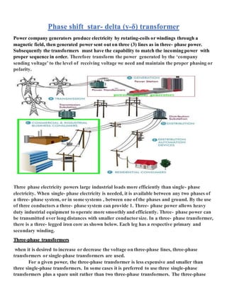
- 1. Phase shift star- delta (y-δ) transformer Power company generators produce electricity by rotating-coils or windings through a magnetic field, then generated power sent out on three (3) lines as in three- phase power. Subsequently the transformers must have the capability to match the incoming power with proper sequence in order. Therefore transform the power generated by the ‘company sending voltage’ to the level of receiving voltage we need and maintain the proper phasing or polarity. Three phase electricity powers large industrial loads more efficiently than single- phase electricity. When single- phase electricity is needed, it is available between any two phases of a three- phase system, or in some systems , between one of the phases and ground. By the use of three conductors a three- phase system can provide 1. Three- phase power allows heavy duty industrial equipment to operate more smoothly and efficiently. Three- phase power can be transmitted over long distances with smaller conductorsize. In a three- phase transformer, there is a three- legged iron core as shown below. Each leg has a respective primary and secondary winding. Three-phase transformers when it is desired to increase or decrease the voltage on three-phase lines, three-phase transformers or single-phase transformers are used. For a given power, the three-phase transformer is less expensive and smaller than three single-phase transformers. In some cases it is preferred to use three single-phase transformers plus a spare unit rather than two three-phase transformers. The three-phase
- 2. transformer is less expensive and smaller than three single-phase transformers. In some cases it is preferred to use three single-phase transformers plus a spare unit rather than two three- phase transformers. Star- delta (y-δ) a star-delta connection, the primary winding of a transformer is connected in a star configuration, and the secondary winding is connected in a delta configuration. The connection diagram of the star-delta configuration is shown in the figure below Phase shift in star delta transformer Positive and negative sequence voltages and currents undergo a phase shift in star delta transformer which depends upon the labelling of terminals. Before considering this phase shift, we need to discuss the standard polarity marking of a single-phase transformer as shown in figure 2 A 3 phase system has peaks at 360 / 3 = 120 degrees. If you were to invert the polarity of your windings you would shift the magnetic fields in the transformer cores by 180 degrees. This would give you 180 - 120 = 60 degrees different from where you were before. The magnetic vectors of a y-δ transformer impose a shift of 30 degrees between the input and output. This means that with judicious terminal selection you can select any desired shift lag of 30, 90, 150, 210, 270, 330 degrees. You can see that it is possible to connect as 30 or 330 (- 30) degrees so you can choose if you want a 30 degree lag or lead. This feature is used in large/expensive polyphase rectification of 3 phase power to minimize the ripple without resorting to capacitors and/or inductors that have their own problems and losses or making them more effective and cheaper. Basically you have the three phase peaks, their opposites due to the full bridge nature of the rectifiers and then from the other set of outputs you get peaks between your 6 peaks giving a 12 peak rectified mains which has a ripple frequency of 600 (720) hz and a voltage sag that is much less.
- 3. star delta and delta connection vector diagram Figure 2 Basic idea of winding An ac voltage applied to a coil will induce a voltage in a second coil where the two are linked by a magnetic path. The phase relationship of the two voltages depends upon which ways round the coils are connected. The voltages will either be in-phase or displaced by 1800 . When 3 coils are used in a 3 phase transformer winding a number of options exist. The coil voltages can be in phase or displaced as above with the coils connected in star or delta and, in the case of a star winding, have the star point (neutral) brought out to an external terminal or not. Phase displacement between hv and lv windings The vector for the high voltage winding is taken as the reference vector. Displacement of the vectors of other windings from the reference vector, with anticlockwise rotation, is represented by the use of clock hour figure. Is: 2026 (part 1v)-1977 gives 26 sets of connections star-star, star-delta, and star zigzag, delta- delta, delta star, delta-zigzag, zigzag star, zigzag-delta. Displacement of the low voltage winding vector varies from zero to -330° in steps of -30°, depending on the method of connections. Hardly any power system adopts such a large variety of connections. Some of the commonly used connections with phase displacement of 0, -300, -180″ and -330° (clock-hour setting 0, 1, 6 and 11).symbol for the high voltage winding comes first, followed by the symbols of windings in diminishing sequence of voltage. For example a 220/66/11 kv transformer connected star, star and
- 4. delta and vectors of 66 and 11 kv windings having phase displacement of 0° and -330° with the reference (220 kv) vector will be represented as yy0 – yd11.the digits (0, 1, 11 etc) relate to the phase displacement between the hv and lv windings using a clock face notation. The phasor representing the hv winding is taken as reference and set at 12 o’clock. Phase rotation is always anti-clockwise. (international adopted).use the hour indicator as the indicating phase displacement angle. Because there are 12 hours on a clock, and a circle consists out of 360°, each hour represents 30°.thus 1 = 30°, 2 = 60°, 3 = 90°, 6 = 180° and 12 = 0° or 360°.the minute hand is set on 12 o’clock and replaces the line to neutral voltage (sometimes imaginary) of the hv winding. This position is always the reference point. Example: Digit 0 =0° that the lv phasor is in phase with the hv phasor digit 1 =30° lagging (lv lags hv with 30°) because rotation is anti-clockwise. Digit 11 = 330° lagging or 30° leading (lv leads hv with 30°) Digit 5 = 150° lagging (lv lags hv with 150° Digit 6 = 180° lagging (lv lags hv with 180°) Transformers are operated in parallel it is important that any phase shift is the same through each. Paralleling typically occurs when transformers are located at one site and connected to a common bus bar (banked) or located at different sites with the secondary terminals connected via distribution or transmission circuits consisting of cables and overhead line. Phase shift (deg 0) Connection 0 lag Yy0 Dd0 Dz0 30 lag Yd1 Dy1 Yz1 60 lag Dd2 Dz2 120 lag Dd4 Dz4 150 lag Yd5 Dy5 Yz5 180 lag Yy6 Dd6 Dz6 150 lead Yd7 Dy7 Yz7 120 lead Dd8 Dz8 60 lead Dd10 Dz10 30 lead Yy11 Dy11 Yz11
- 5. six ways to wire star winding: Six ways to wire delta winding: The phase-bushings on a three phase transformer are marked either abc, uvw or 123 (hv-side capital, lv-side small letters). Two winding, three phase transformers can be divided into four main category Group O’clock Tc Group i O’clock,00 Delta/delta, star/star Group ii 6’clock, 1800 Delta/delta, star/star Group iii 1’clock,-300 Star/delta, delta/star Group iv 11’clock,+300 Star/delta, delta/star **+Minus indicates lv lagging hv, plus indicates lv leading h
- 6. Group iii 1’clock,-300 Star/delta Group iv 11’clock,+300 Star/delta Logically , Clock notation 5 (phase displacement -1500 degree) Clock Notation 7 (Phase Displacement +1500 Degree)