
Recommended
More Related Content
Similar to thyrister-160302163810.pptx
Similar to thyrister-160302163810.pptx (20)
More from ANANDHUPILLAI1
More from ANANDHUPILLAI1 (13)
Recently uploaded
Recently uploaded (20)
thyrister-160302163810.pptx
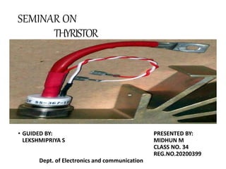
- 1. SEMINAR ON THYRISTOR • GUIDED BY: PRESENTED BY: LEKSHMIPRIYA S MIDHUN M CLASS NO. 34 REG.NO.20200399 Dept. of Electronics and communication
- 2. Introduction Thyristerisa three terminal device having Gate Anode and Cathode. Anode Ispositive and Cathode isnegative terminal Gate terminal fora controlling input signal
- 3. SCR/Thyristor A thyristor is normally four layer three-terminal device. Four layers are formed by alternating n –type and p –type semiconductor materials. Consequently there are three p –n junctions formed in the device. It is a bistable device. The three terminals of this device are called anode (A), cathode (K) and gate (G) respectively.
- 4. Structure on the physical and electronic level, and the thyristor symbol.
- 5. • Thyristors have three states: 1.Reverse blocking mode – Voltage is applied in the direction that would be blocked by a diode. 2.Forward blocking mode – Voltage is applied in the direction that would cause a diode to conduct, but the thyristor has not been triggered into conduction. 3.Forward conducting mode – The thyristor has been triggered into conduction and will remain conducting until the forward current drops below a threshold value known as the "holding current“.
- 6. Thyristor discovery • The idea for the thyristor was first described by Shockley in 1950. • It was referred to as a bipolar transistor with a p-n hook-collector. • The mechanism for the operation was analysed further in 1952 by Ebers. • Then in 1956 Moll investigated the switching mechanism of the thyristor. • Development continued and more was learned about the device such that the first silicon controlled rectifiers became available in the early 1960s where it started to gain a significant level of popularity for power switching.
- 7. Basic Operating Principle ofThyristor The basic working principle in the SCR is that as the triggering or the biasing is applied at the terminal gate then the conduction begins. As it is a unidirectional device the current will be in a single direction. It resembles the operation of the diode but the only difference is that this can withstand the high amount of voltages and powers.
- 8. Basic Construction of Thyristor An SCR is constructed with the four layers that consist of the P-type and the N-type semiconductor material. These are layered in such a way that it tends to form three junctions that are J1, J2, and J3. The three terminals that are attached to it are known as anode, cathode, and gate. SILICON CONTROLLED RECTIFIERS (SCR) A silicon controlled rectifier is a semiconductor device that acts as a true electronic switch. It can change alternating current and at the same time can control the amount of power fed to the load. SCR combines the features of a rectifier and a transistor.
- 9. Construction of Thyristors • Thyristors can be understood with the help of two transistor analogy. • The collector of one transistor is connected to the base of the second transistor while the collector of the second transistor is connected to the base of the first transistor. • Thus, total four layers of semiconductor material are connected to each other and total three junctions are formed. • In thyristors, there are three terminals that are anode, cathode and gate. Gate terminal provides the controlling voltage.
- 10. Types of Thyristor • There are various semiconductor devices which can be classified under the thyristor family. Some of the most used devices are SCR, DIAC, TRIAC, GATT etc..
- 11. Characteristics of Thyristors • The characteristics curve of Thyristors is shown in the diagram below. With the help of characteristics curve, we can understand its working in forward biased mode and reversed biased mode in a detailed manner.
- 13. Advantages of Thyristors 1.Better Efficiency: Thyristors possess better efficiency than transistors, thus it is used in various application of electronics. 2.Low cost of Fabrication: The cost of fabrication of thyristors is low and thus it is economical to use in various electronics circuits for switching operation. 3.Ability to be controlled: This is the robust characteristics of the thyristor as because of the gate terminal the thyristor can be controlled. 4.High Reliability: The thyristor is the highly reliable device, and thus is used as a significant part in HVDC transmission.
- 14. Disadvantages of Thyristor : It can not be negative. It can not be used higher frequency. It can not be easily turn off. In the AC circuit, it need to be turn on each cycle. Gate current can not be negative.
- 15. Applications of Thyristors 1.Rectification Purpose: The thyristors are used for rectification of AC signal. Thus, when the controlled signal is given to rectifier it converts AC into DC. 2.Relay Control: Thyristors are used in relay control. 3.Phase Control: The phase controller used thyristors for providing phase correction in the circuit. 4.HVDC transmission: They are also used in high voltage DC transmission. 5.Control of temperature, level and Position: Due to its robust controlling, it can be used for controlling the temperature, level, position and illumination.
- 16. CONCLUSION • It is a power elelctronic device. • It controls high voltage and current. • Working in between 50 to 10khz frequency. • Controlling is very easy. • Triggering voltage is very less.