
Recommended
More Related Content
What's hot
What's hot (20)
Similar to Cathode Ray Oscilloscope: The Heart of Waveform Analysis
Similar to Cathode Ray Oscilloscope: The Heart of Waveform Analysis (20)
More from AKSHIT KOHLI
More from AKSHIT KOHLI (19)
Recently uploaded
Recently uploaded (20)
Cathode Ray Oscilloscope: The Heart of Waveform Analysis
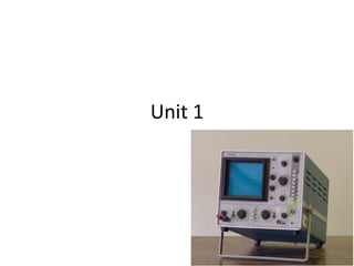
- 1. Unit 1
- 2. • Cathode ray oscilloscope: most useful lab instrument for studying waveshapes of alternating currents & voltages, measurement of voltage, current, power & frequency (any qty that involves amplitude & waveform) • Allows user to see amplitude of electrical signals as a ftn of time on the screen • The CRO depends on the movement of an electron beam which is deflected on the x and y axis.
- 4. Parts of CRO An oscilloscope consists of two parts- • Cathode ray tube • Control and input circuitry
- 5. CRT • Cathode ray tube is the heart of the oscilloscope. • The CRT makes the applied signal visible by the deflection of a thin beam of electrons. – Generates the electron beam – Accelerates the beam to a high velocity, – deflects the beam to create an image – Contains a phosphor screen where the electron beam becomes visible
- 6. • Low voltage supply: for heater of the electron gun for generation of electron beam • High voltage supply: for CRT to accelerate the electron beam • Normal voltage supply: for other control ckts in CRO
- 7. • Horizontal & vertical deflection plates fitted btwn electron gun & screen to deflect the beam acc to input signal • Elec beam strikes the screen & creates a visible spot: spot deflected on the screen in the hor direction (X axis) with constant time dependant rate • The signal to be viewed is supplied to the vertical deflection plates through the ver amplifier: raises the potential of the input signal : provide usable deflection of electron beam
- 8. • Elec beam deflects in 2 directions: X (hor) & Y (ver) • Triggering ckt provided for synchronizing the two types of deflection : hor deflection starts at the same point of input ver signal each time it sweeps
- 9. • Main parts of CRT are- – Electron gun assembly: for producing a stream of electrons – Deflection plate assembly: for controlling the beam path – Fluorescent screen – Glass envelope: evacuated glass envelope with phosphor screen giving bright spot when struck by a high vel electron beam – Base: connections made to diff components
- 10. 1. Electron gun assembly • Consists of – Indirectly heated cathode – Control grid surrounding the cathode – A focusing anode & accelerating anode • Ftn: to provide a focused elec beam accelerated towards the phosphor screen • Cathode: heated -> emits plenty of elec; emitting surface as small as possible. Rate of emission of elec depends on the magnitude of cathode current controlled by control grid • Beam comes out of control grid through a small hole & enters pre-accelerating anode (more positive than cathode: to accelerate the beam in electric field)
- 11. • Accelerated beam gets scattered (variations in energy): – lead to ill defined spot on screen – So focussing: by electrostatic lens (focussing anode & accelerating anode: these concentrate & focus the beam on screen & accelerate the speed of elec)
- 12. 2. Deflection plate assembly • Elec beam passes through the 2 pairs of deflection plates – One pair: mounted vertically: deflects beam in hor or X direction: X plates – Other pair: mounted horizontaly: deflects beam in ver or Y direction: Y plates • Deflect the beam acc to the voltage applied across them • Eg: a const pd applied to Y plates: elec beam will deflect upward if upper plate is positive: deflect downward if lower plate is positive
- 13. 3. Screen • Crystalline mat like phosphor: property of emitting light when exposed to radiation: fluorescence (electrical energy to light energy) – Phosphoroscence: fluorescent mat continue to emit light even after radiation exposure is cut off – Length of time during which it occurs: persistence • End wall of CRT coated with phosphor; when elec beam strikes the CRT screen, a spot of light is produced, phosphor absorbs kinetic energy of bombarding elec & emits energy
- 14. • Luminance: intensity of light emitted from CRT screen depends on: – no of bombarding elec striking the screen/sec – The energy with which the bombarding elec strike the screen – Time the beam strikes a given area of the screen : sweep speed – Physical char of phosphor
- 15. 4. Glass body & base • CRT assembly protected in a conical evacuated glass housing • Inner walls of CRT btwn neck & screen are usually coated with a conducting material: aquadog : – coating is electrically connected to accelerating anode – Coating provided to accelerate the elec beam after passing btwn deflectig plates & collect elec produced by secondary emission when elec beam strikes the screen – Prevents formation of –ve charge on the screen – Graticule: hor & ver marks are marked on the screen to provide user a correct measurement
- 16. Focusing device • Beam coming out of accelerating anode has a tendency to spread from the axis: because of mutual repulsion btwn electrons • To bring beam to sharp focus at screen: focusing device • Electrostatic focusing in CRO: Electrostatic lens consists of 3 anodes (middle anode at lower potential than other 2)
- 17. Electrostatic focusing in CRO • In fig, 2 anodes & its electrostatic lines & equipotential surfaces • A pot diff is kept btwn the electrodes: elec field generated • Spreading of elec field caused (bcos of repulsion btwn electric field lines): equipotentials would bulge at the centre of the anodes • Electrons move in direction opp to that of elec field lines • Equipot surfaces are perpendicular to elec field lines : force on elec exerted in direction normal to the equipot surface
- 18. • Fig: elec entering at the centre line of the two anodes experience no force • Elec displaced from centre: experience force normal to the direction of equipot surface & deflects • Elec with vel v1, at angle θ1 enters & experiences force : vel increases to v2. (force on elec only in direction normal to the equipot surface: only normal component v1N increases to v2N; tangential comp v1T remains same ) • v1T = v1 sinθ1; v2T = v2 sinθ2 As v1T = v2T , so v2/v1 = sinθ1/sinθ2 • Equipot surface acts as concave lens: electrostatic lens
- 19. ES deflection of moving elec in CRT • Principle: Force exp by elec when kept in uniform elec field • Consider : elec with initial vel u (along X-axis at O btwn plates A & B); length of A =B= l ; dist btwn A & B = d; pot diff across plates= V • Period during which an elec remains in region btwn A & B : t= l /u • No initial vel along Y axis, but acceleration = • Vel of elec along Y axis after time t
- 20. • After leaving the plate region, elec travels in a strght line (as no field acts). If this line is extended backward, it intercepts the X axis at the centre of the plates at x= l /2 • S: dist along X axis from this point x; deflection y determined by similar triangles • Va= accelerating voltage; • Vd= deflecting voltage • Substitute u2 in y
- 21. • So, For a fixed accelerating voltage Va, the deflection of elec beam on the screen is directly prop to the deflection voltage Vd: CRT is linear voltage indicating device (image follows variations in Vd in linear manner) • Deflection sensitivity: vertical defl of the beam on screen per unit deflecting voltage • Deflection factor: 1/ Deflection sensitivity
- 22. Post Deflection Acceleration • After electrons pass beyond the deflection plates, they may or may not experience additional acceleration. • This depends primarily upon on the max freq to be applied to CRT. • For good sensitivity Ea should be low below 4 kV but reduces brightness, which can be seriously impaired at high frequencies. • Below 10 MHz ,monoaccelerator may be used. • If signals of frequencies higher than 10 MHz are to displayed, post deflection acceleration tubes (PDA) or post accelerators is necessary to increase the brightness of the trace which otherwise would be dim.
- 23. Basic controls • No of controls reqd in CRO to facilitate proper ftning • Intensity control provided for adjusting brightness of spot on screen: by varying voltage btwn 1st and 2nd anodes • Hor & ver position controls: for moving the beam on ay part of screen : by applying dc voltage to defl plates 1. Ver defl system 2. Hor defl system 3. Position control (knobs to move the spot hor: left/ right or ver: up/down) 4. Intensity control: by grid potential (ie the amount of elec leaving the cathode; large number= brighter spot)
- 24. 5. Focus control: focusing elec beam by varying pot of middle anode (ES lens) 6. Astigmatism: Additional Focus control 7. Banking ckt: hor defl plates have sawtooth sweep voltage ( this moves the spot on the screen during sweep period) : retrace time in sawtooth waveform should be zero; if not blank it by supplying high –ve voltage to the grid during retrace. 8. Calibration ckt: an oscillator for generating known & fixed voltage in square waveform
- 25. Time base generator • Time base: axis used to represent time so that variations of qty like voltage, current can be plotted wrt time • For movement of spot, voltage (linearly varying with time) is applied to one defl plates pair. This voltage sweeps elec beam across screen: sweep voltage (shape is sawtooth / ramp) • The ckt which develops this linearly time varying voltage : Time base generator/ sweep ckt
- 26. • Fig: voltage starts from some initial value , increases linearly with time to a max value & then returns to initial value • Time req to return to initial value: Restoration time / flyback time (Tr) • Time of linear portion: sweep time (Ts) • (Tr) << (Ts) • Idealized sweep: Tr zero & exact linear sweep; Practically: deviation from linearity 1. Slope or sweep speed error: – Ratio: difference in slope at the beginning & end of sweep/ initial value or slope
- 27. 2. Displacement error: – Ratio: max difference btwn actual sweep volt & linear sweep volt passing through the beginning & end points of sweep / max value attained by sweep voltage – Define non-linearity of time base signal 3. Transmission error: – Ratio: difference btwn max amplitude of I/P & O/P signals to max amplitude of signal
- 28. Types of TBG 1. Volt TBG: generate a voltage linearly varying with time (ES defl: CRO) 2. Current TBG: generate a current linearly varying with time & this current is caused to flow through inductors or defl coils (EM defl: TV) • Other categorization: – Triggered : generates a cycle & then comes back to its stable state; the pulse rate depends on freq of applied trigger – Free running: switches back & forth btwn 2 levels & freq depends on ckt parameters – Synchronized: freq of oscillation determined by synch voltage
- 29. Types of sweeps • 1. free-running/ recurrent – Sawtooth waveform is repetitive: new sweep stared immediately after the previous sweep is terminated & ckt is not initiated by any external signal • 2. triggered / single – Used when waveform to be observed is not periodic: so desirable to keep sweep ckt inoperative & initiate the sweep by waveform – The spot is swept once across the screen in response to a trigger signal: used for examination of transient or one time signal • 3. Driven – Used where sweep is recurrent but triggered by signal under investigation • 4. Non-sawtooth – Used for applications like comparison of 2 freq or for determining the phase shift btwn 2 voltages and the sweep freq vary with type of oscilloscope
- 30. Multiple Trace Oscilloscope • In analysis of elec ckts & systems : view behavior of 2 or more voltages simultaneously: use 2 oscilloscopes? (cost, precise synchronization in triggering, comparison tough) • Soln: special CRO: uses 2 separate elec guns & defl systems in same CRT: 2 diff elec beam displayed simultaneously – Dual Beam Oscilloscope – Dual Trace Oscilloscope
- 31. Dual Beam Oscilloscope • Display 2 simultaneous non-current signals • Eg: I/P & O/P of a pulse shaping ckt both exhibited on same screen • In Dual beam CRO, 2 channels can have common time base system or independent • Common: Only one beam synchronized at a time: both inputs must have same freq; Independent: allows diff sweep rates for 2 beams • 2 methods to obtain separate beams: – The O/P of a single electron gun mechanically split into 2 separate beams: Split-beam technique (drawback: 2 displays have diff brightness) – 2 separate elec gun (allows brightness & focus of each beam to be controlled ; drawback: bulkier)
- 33. Dual Trace Oscilloscope • Single elec gun : produces dual trace display by electronic switching of 2 separate i/p signals. • 2 separate vertical i/p channels with separate attenuator & preamplifiers: amplitude of each signal independently controlled • O/ps of preamplifier supplied to elec switch : passes one signal at a time into main vertical amplifier of oscilloscope • Operating modes: – Alternate – Chop mode
- 36. • Alternate : – Elec sw feeds each signal alternately to vertical amplifier. It adds a diff dc component to each signal which directs the beam alternately to upper or lower half of screen – Switching done at the start of each new sweep of TBG: channel A signal on one sweep, channel B signal on next • Chop mode – Elec sw free runs at high freq (100-500khz) ; independent of the freq of TBG. – Small segments from btoh channels are connected alternately to main ver amp at a fast chopping rate – chopping rate >> hor sweep rate: continuous display for each channel (<< : continuity lost so btr use alternate mode) • Added mode: single image displayed by addition of signals from both channels (polarity inversion sw in channels allow A+B, A-B, etc. )
- 37. • When the signal to be displayed is of a very high frequency ,the electron beam does not get sufficient time to pick up the instantaneous level of the signal. • Also at high frequencies the numbers of electrons striking the screen in a given time and the intensity of the beam is reduced. • Instead of one set of deflection plates,a series of vertical deflection plates are used. • The plates are so shaped and spaced that an electron travelling along the CRT receives from each set of plates an additional deflecting force in proper time sequence. High frequency crt or travelling wave type crt
- 38. • This synchronisation is achieved by making the signal travel from one plate to the next at the same speed as the transit time of the electrons. • The signal is applied to each pair of plates,and as the electron beam travels the signal also travels through the delay lines. • The time delays are so arranged that the same electrons are deflected by the input signal. High frequency crt or travelling wave type crt
- 39. 1. The vertical amplifier must be designed both for high B.W. and high sensitivity or gain. Making the vertical amplifier a fixed gain amplifier simplifies the design. The input to the amplifier is brought to the required level by means of an attenuator circuit. the final stages is the push-pull stage. 2. The LF CRT is replaced by an HF CRT. 3. A probe is used to connect the signals,e.g. a high Z passive probe acts like a compensated attenuator. 4. By using a triggered sweep,for fast rising signals,and by the use of delay lines between the vertical plates,for improvement of HF characteristics. Characteristics of a HF CRO(HF improvement in a CRO)
- 40. Sampling Oscilloscope • Display repetitive signals (with freq higher than HF osc) • Signal reconstructed from sequential samples of its waveform • Samples obtained at slightly diff points along successive cycles of signal waveform: repetitive waveform so that sampling can be done • Sampling pulse turns on osc measuring ckt for a brief time: ver posn of beam controlled by resulting voltage observed at that point • Following pulse samples the waveform in its next cycle at slightly diff point • Hor posn: stepped fwd very slightly & ver posn: determined by new voltage • Bandwidth of amplifier reqd to handle HF waveforms can be much lower than the freq of waveform
- 41. • Repetitive i/p waveform applied to sampling gate • Sampling pulse bias the diodes of balanced sampling gate in fwd direction: connects gate i/p capacitance to test point • Ver amplifier amplifies capacitor voltage & applied to ver defl plates • Signal delayed in ver amp: sweep triggering initiated by i/p signal
- 43. Storage oscilloscope • The purpose of storage oscilloscope is to freeze images or store them for later analysis. These types of oscilloscopes are useful for single shot events such as transients, glitches. • Types of storage oscilloscopes are: 1.Analog Storage oscilloscope 2.Digital Storage oscilloscope
- 44. Analog storage osc • Secondary elect emission to build up & store electrostatic charges on surface of an insulated target • Used for • Real-time observation of events that occur only once • Displaying waveform of a very low freq signal • Types: 1.Variable persistence storage. 2.Bistable Storage oscilloscope
- 45. Secondary elec emission • When beam of high vel elec suddenly strike a metallic surface, kinetic energy transfers to electrons & atoms they strike • Some Primary elec (bombarding elec) collide directly with free elec on metal surface & knock them out : Emission of elec called secondary emission (secondary electrons) • No of sec elec depends on: – No of primary elec – Energy of primary elec – Angle of incidence of elec at surface – Type of emitting material
- 46. • Evacuated glass envelope with emitter E, collecting anode A, & a source of elec • Anode +ve wrt E • When elec emitted by elec source S (primary elec) strike emitting surface E at high speed, elec knock out from E: sec elec (attracted towards the anode) : constitute a flow of current in external ckt
- 47. Digital Storage Osc • The input signal is converted into a digital form and stored in memory. It is then converted back into analog signal, reconstructed and presented to CRT display. • The logic control provides the synchronous operation of the oscilloscope. its functions include: 1)To receive trigger pulses. 2)To determine sampling rate of ADC. 3)Controlling entry of data into store. 4)Controlling the release of data stored into DAC. 5)Controlling DAC by determining its speed and release of data of the CRT.
- 49. -In high frequency and pulse applications,the input capacitance of the oscilloscope begins to load the circuit. -The effect of probe is to increase the input resistance of the oscilloscope. Oscilloscope probes
- 50. 1)Direct /Passive Probes It is simplest of all the probes. Uses shielded co-axial cable. Avoids stray pick-ups which may create problems when low level signals are being measured. Usually used for low frequency or low impedance circuits. Types of probes
- 51. Using the shielded probe, the shunt capacitance of the probe and cable is added to the input impedance and capacity of the scope and acts to lower the response of the oscilloscope to high impedance and high frequency circuits. External high impedance probes are used to increase the input resistance and reduce the effective input capacitance of an oscilloscope. Types of probes
- 52. 2)Active Probes:- Block diagram of FET probe Types of probes
- 53. Passive probe is mostly used voltage probe. It is apparent that low capacitive loading can be obtained at the expense of considerable attenuation. These problems can be overcome by using active (FET) probe. Types of probes
- 54. 3)CURRENT PROBES- TYPES of probes
- 55. The arrangement of figure which have a core that may be slid open to allow the current carrying conductor to be inserted. This works on principle of transformer,with one winding of the transformer being the measured wire. The probes using this principle are used for a.c. measurements only. TYPES OF PROBES
- 56. Oscilloscopes are designed for voltage,but can be used to measure current using current probe. The current probe has set of jaws which encloses the wire that the measured current is flowing through. No connection is required. TYPES of probes
Editor's Notes
- 6 Centre pe focus ki hui beam edges pe defocus ho jaegi bcoz dono elec path ki length diff hogi centre n edge k lie 7 if spot moves slowly : exceeds persistence vision threshold: spot appears as solid line; If movement is fast: thin /dim line or invisible Retrace time zero nhi hota practically jisse confusion hoti h spot right to left move krta hai
- Spot ko screen pe move karne ke lie kisi b deflection plate pe voltage apply krte h jo time k sath vary krti hai