
Recommended
More Related Content
What's hot
What's hot (20)
Viewers also liked
Viewers also liked (14)
Similar to Hot water flow controller function description
Similar to Hot water flow controller function description (20)
Recently uploaded
Recently uploaded (20)
Hot water flow controller function description
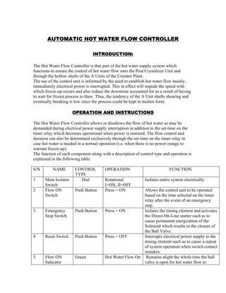
- 1. AUTOMATIC HOT WATER FLOW CONTROLLER INTRODUCTION: The Hot Water Flow Controller is that part of the hot water supply system which functions to ensure the control of hot water flow onto the Post Crystalizer Unit and through the hollow shafts of the A Units of the Unitator Plant. The use of the control unit is informed by the need to establish hot water flow mainly, immediately electrical power is interrupted. This in effect will impede the speed with which freeze-up occurs and also reduce the downtime accounted for as a result of having to wait for frozen process to thaw. Thus, the tendency of the A Unit shafts shearing and eventually breaking is low since the process could be kept in molten form. OPERATION AND INSTRUCTIONS The Hot Water Flow Controller allows or disallows the flow of hot water as may be demanded during electrical power supply interruption in addition to the set-time on the timer relay which becomes operational when power is restored. The flow control and duration can also be determined exclusively through the set-time on the timer relay in case hot water is needed in a normal operation (i.e. when there is no power outage to warrant freeze-up). The function of each component along with a description of control type and operation is explained in the following table: S/N NAME CONTROL TYPE OPERATION FUNCTION 1 Main Isolator Switch Dial Rotational I=ON, II=OFF Isolates entire system electrically. 2 Flow ON Switch Push Button Press = ON Allows the control unit to be operated based on the time selected on the timer relay after the event of an emergency stop. 3 Emergency Stop Switch Push Button Press = ON Isolates the timing element and activates the Direct-On-Line starter such as to cause permanent energization of the Solenoid which results in the closure of the Ball Valve. 4 Reset Switch Push Button Press = OFF Interrupts electrical power supply to the timing element such as to cause a repeat of system operation when switch contact remakes. 5 Flow ON Indicator Green Hot Water Flow On Remains alight the whole time the ball valve is open for hot water flow to
- 2. concerned parts 6 Emergency Stop Indicator Red Emergency Stop Stays alight until the Flow On Switch is pressed i.e. when hot water flow should resume. 7 Contactor K1 K2 Electromagnet ic attraction Electromagnet ic attraction Energized switching 2122 = OFF 4344 = ON Energized switching 1314 = ON i) Contacts are actuated for establishing or interrupting d.c power supply meant for energizing the 24V solenoid valve coil. ii) The 240Vac supply to the Flow on Indicator Contacts are actuated for establishing or interrupting d.c power supply meant for energizing the 24V solenoid valve coil. 8 Emergency Stop Relay K3 Electromagnet ic attraction Energized switching = ON De-energized switching = OFF The Relay is used to achieve Direct- On-Line Starter wiring to ensure emergency stop and control of voltage supply to the timing element. 9 Timer Relay Timed-based Electromagnet ic attraction. Energized switching 1516 = NC 15/18 = NO It determines the duration of hot water flow by of means of the selector it bears. 10 Solenoid Valve Electromagnet ic Induction Energized Coil = Close De-energized Coil = Open Controls the flow of air into the electropnuematic actuator. 11 Electropnuem atic Actuator Dial Rotational Transmits its rotational motion to the ball valve causing it open or close. 12 Ball Valve Dial Rotational It opens or closes to allow or disallow respectively the flow of hot water through the system onto concerned parts 13 Manual Air Valve Dial Rotational It serves as a means of cutting off the air supply to the electopnuematic valve such as to ensure a fail-safe idle time i.e. ensuring the permanent closure of the ball valve until it is needed otherwise.
- 3. FLOW ROUTING The hot water passing through the ball valve is eventually distributed and directed to flow through the hollow shafts of the A units and through the pipe laid by the Post Crystallizing Unit (PCU). To minimize splashing which could result in water ingress into prohibited areas, the summation of the cross sectional areas of the outlets (i.e. the outlet areas of the pipe by the PCU and those on the A Unit Shafts) is taken to be three times larger than the cross sectional area of the inlet (i.e. the cross sectional area of the Ball Valve bore). Fig: Flow Route Diagram Considering the diagram above, Cross sectional area of the Inlet valve = Ain) Summation of the cross sectional areas of the outlets = A1 + A2 + …… A(n) = A(out) Given the Mass flow rate: Avρ = C Where: A is the cross sectional area of the passage V is the velocity of flow ρ is the density of working fluid being constant
- 4. Then, AV = C Assuming flow rate to be constant in the system, Then, Ain Vin = Aout Vout But in order to minimize splashing, the outlet velocity is taken to be 1/3 of the inlet velocity. Hence, Vin = 3 x Vout From the Mass flow rate Equation, i.e. Ain Vin = Aout Vout Substituting for Vin, we have; Ain 3 x Vout = Aout Vou Therefore, Aout = 3Ain This implies that for a gentle flow to be obtained at the outlet, the summation of the outlets area must be three times as much as the inlet area.