SlideShare a Scribd company logo
1 of 21
Phase 1: Identifying Requirements, Putting the Network Together
Scenario
NuggetLabs Industries is growing significantly. Due to space limitations, five employees currently
sharesinglecubicles…at the same time. Whilethis is great for team building, these space limitations are now
impacting business productivity. NuggetLabs has now leased an additional office building roughly 20Km from
their headquarters location. Whilethisoffice will eventually connect to the HQ office, it willinitially be set up
independently. NuggetLabs Industries has heard rumors of your ninja-like networkconsultation skills and has
agreed to pay you an excessive amount of money to design and buildtheir network infrastructure.
Gathering Information
To help guide this initial configuration, you‘ve assembled a list of requirements based on various meetings with
management.
The new office will initially house 75 employees, each with their own Cisco IP Phone and PC. This office
may eventually scale to 200 employees over 5 years.
The Windows admins are planning to install a new pair of redundant servers at the new office. They plan
to manage all the IP addresses for DHCP on these servers and are waiting for you to tell them what IP
address range they should use.
o Windows admins: Jeff Service - (602) 555-1293, Mike Pack (480) 555-9382.
The new office is a two story building with the Main Distribution Frame (MDF) in the northwest corner of
the first floor. Because of a workman’s strike, poor planning, and other human issues, the Intermediate
Distribution Frame (IDF) on the second floor was installed in the southeast corner of the second floor,
beyond the reach of typical Ethernet standards. The majority of the employees (roughly 50) will sit on the
main floor while the remainder will sit on the second floor. The building contractor has already run the
cabling - a single Cat6 Ethernet connection to each cubical / office space which terminates to patch panels
in the MDF/IDF area.
NuggetLabs is planning to use a Voice over IP (VoIP) phone system for the new office. Each user will have
an assigned IP Phone in their cubical / office space. The installation / management of the phone system
itself will be the responsibility of another company; however, the network should be prepared to support
the additional devices.
The new office will need WIFIimplementations, soto keep budgets in checkthe company would liketo use
off-the-shelf Cisco Small Business WAPs. These WAPs are to host two wirelessnetworks: NL-CORP and NL-
PUB. Those connecting to NL-CORP should have access to the corporatenetwork and resources. Of course,
high-end security is mandatory for this wireless network. Thoseconnecting to NL-PUB should not be
prompted for any security requirements but should be limitedto Internet access only.
NuggetLabs Industries would like you to assess the network and make recommendations on
Internetconnectivity options. They would also like to begin evaluating network connections between
theiroffices.
During the discussions, NuggetLabs Industries found that you work primarily from your home
office.Because of the value NuggetLabs places on your technical prowess, they have offered to provide
anoffice space located in the MDF for you to use as a lab environment; a "home-away-from-home” youcan
use. However, this lab environment must be completely isolated from the corporate network to not cause
any interference to day-to-day operations.
Priority Client Task Time Assigned
1 NL Initial Meeting with NL Corporate
Create initial questionnaire for on-site visit 30
Discuss upcoming branch office rollout (goals, staff
involvement, key contacts)
180
1 NL Create NL Proposal
Requirements Document 15
Equipment Order 240
VLAN / Subnet List 30
Switchport Connections 30
Physical Visio Diagram 30
Logical Visio Diagram 30
Objective
Based on this information, NuggetLabs Industries would like you to create a proposal, design, and
implementation plan for their new office by next Friday. The submission should include the following elements:
Requirements Document
Equipment Order
VLAN(s) - Necessary
IP Subnet(s) - Necessary
Switch Port Connections
Any Necessary Visio Diagrams
Requirements Document
Based on company meeting, November 28th, 2011
Attendees
Bob Phaman [CEO - BobP@nuggetlabs.com – (602) 555.2791]
Sarah Belittle [CTO - SarahB@nuggetlabs.com –(602) 555.8329]
Jeff Service[Windows Admin Lead - .JeffS@nuggetlabs.com –(602) 555.1293]
Mike Pack [Desktop Support - MikeP@nuggetlabs.com – (480) 555.9382]
Grapler Construction Company (various reps) [support@grapler.com]
Requirements
Network must initially handle 75 users between two floors
Network must handle both VoIP and Data traffic
Network should handle public(unsecure) and private (secure)WIFI
Private office / lab area created in MDF, separate from the network
Suggest optionsforInternet connectivity
Assumptions
Each user will have one workstation
Each user will haveoneIP phone
Network should handle 1 Gbps Ethernet connectionstothe desktop
Dual fiberopticcabling run completed from MDF to IDF
Internet connectivity options will be suggested, agreed upon, and installed before the move in date
Allcable runsterminatetotheIDF or MDF
Each cubical/office will have at least one Cat6Ethernet connection
JeremyC Consulting Inc. will be ordering all necessary equipment and patch cables for the operation
Windows servers willhave redundantconnections
IDF will be initially set up with a 48 port switch (allowing approx. 48% growth)
MDF will be initially set up with two48 port switches(allowing approx. 44% growth)
PCs and IP Phones will be located no more than 3m from the wall connection, 1.5-2m on average.
Single Internet router (no redundancy) is acceptable
Single core L3 switch (no redundancy) is acceptable
PSTN callingforVoIP network will be handled via SIPTrunk over the Internet
MDF and IDF have sufficient powerand coolingforthe equipmentto be installed
Phase 1: Brainstorming
Requirements
Two stories
o First Floor MDF - initially housing 50 users, servers, etc...
o Second Floor lDF - initially housing 25 users
WIFI
o Full coverage for first and second floor
o Need to perform a wireless site survey (onsite)
o Power over Ethernet switches or couplers
VoIP
o IP Phone per cubical / office
o Need additional 1.5-3m Cat 5E / 6 Ethernet cabling as PC patch
Priority Client Task Time Assigned
2 NL Onsite Visit
WiFi Site Survey 120
Get with Windows guys to determine cabinet 60
Items Needed
MDF - two 48-port PoE switches, one of them should be Layer 3 capable
o Cisco LAN Access Switches
o Cisco 2960 Model Comparison
o Cisco 3750-X Model Comparison
o First Choice L2 Switch - WS-C2960S-48FPS-L
 48-port, L2 switching
 740W PoE (15W per port)
 (4) 1G SFP Uplinks
o First Choice L3 Switch - WS-C3750X—48PF-S
 48-port, L3 Switching
 740W PoE (1.5W per port)
 (4) 1G SFP Uplinks
o Mounting- wall mount? Server cabinet? (determine server needs)
o Cabling- need plenty of spare 1.5m, 2m, and 3m cables for cubicles. Offices, server connections
o Fiberopticconnection: Patch cables and two SFPs
MDF - one Internet router
o Cisco Routers
o Cisco 2900 Series
o First Choice Router — Cisco 2901
 (2) 1 Gbps built-in interfaces
 (4) card slots (expansion using serial, ethernet, etc...)
 Voice capabilities (on-board DSPs)
IDF - one 48-port PoE switch
o First Choice L2 Switch - WS-C2960S-48FPS-L
 48-port, L2 switching
 740W PoE (15W per port)
 (4) 1G SFP Uplinks
Building - Wireless access points
o Cisco Small Business WIFI options
o First Choice - WAP4410N
 802.11n/g/b
 1Gbps, PoE Capable (802.3af)
 Supports4 VLANs, 4 SSlDs
Equipment List
Name Device Function Location T1 1G 10G
NL-B1-SW1 3750X Core L3 Switch MDF 48
NL-B1-SW2 2960S L2 Switch MDF 48
NL-B1-SW3 2960S L2 Switch IDF 48
NL-B1-RT1 2901 Internet Router MDF 2
NL-B1-WI1 WAP4410N WiFi Access Point Ceiling 1
NL-B1-WI2 WAP4410N WiFi Access Point Ceiling 1
NL-B1-WI3 WAP4410N WiFi Access Point Ceiling 1
Name Device Qty Function T1 1G 10G
NL-B1-SW1 WS-C3750X-48PF-S 1 Core L3 Switch 48
4 Port Gigabit SFP C3KX-NM-1G 1 4
Redundant PSU C3KX-PWR-715WAC 1
SMARTnet 1
Fibre SFP (SX) GLC-SX-MM 4
Rack Mount Kit C3KX-RACK-KIT 1
IP Addressing Scheme
Network Mask VLAN Description
10.1.1-63.0 255.255.192.0 Corporate Office
10.1.64.0 255.255.254.0 VLAN 64 Client VoIP
10.1.65.0
10.1.66.0 255.255.254.0 VLAN 66 Client Data
10.1.67.0
10.1.68.0 255.255.255.0 VLAN 68 Server
10.1.69.0 255.255.255.0 VLAN 69 Public WiFi
10.1.70.0 255.255.255.0 VLAN 70 Lab
10.1.71.0 255.255.255.0 VLAN 71 Network Management
107.20.176.240 255.255.255.240 VLAN 10 Internet DMZ
Branch 1 Summary: 10.1.64.0/21 (255.255.248.0)
VLAN 64 – Client VoIP
IP Address Mask VLAN Description
10.1.64.0 255.255.254.0 64 Client VoIP Network
10.1.64.1 NL-B1-SW1 VLAN 64 IP (Default Gateway)
10.1.64.2-10 Reserved
10.1.64.11 to
10.1.65.245
Client VoIP DHCP Scope
10.1.65.246-254 Reserved
10.1.65.255 Client VoIP Broadcast
VLAN 66 – Client Data
IP Address Mask VLAN Description
10.1.66.0 255.255.254.0 66 Client Data Network
10.1.66.1 NL-B1-SW1 VLAN 66 IP (Default Gateway)
10.1.66.2-10 Reserved
10.1.66.11 to
10.1.67.245
Client Data DHCP Scope
10.1.67.246-254 Reserved
10.1.67.255 Client Data Broadcast
VLAN 68 – Server
IP Address Mask VLAN Description
10.1.68.0 255.255.255.0 68 Server Network
10.1.68.1 NL-B1-SW1 VLAN 68 IP (Default Gateway)
10.1.68.2-5 Reserved
10.1.68.6 NL-B1-DC01
10.1.68.7 NL-B1-DC02
10.1.68.8 NL-B1-CUCMBE
…
10.1.68.251-254 Reserved
10.1.68.255 Server Broadcast
VLAN 71 – Network Management
IP Address Mask VLAN Description
10.1.71.0 255.255.255.0 71 Management Network
10.1.71.1 NL-B1-SW1
10.1.71.2 NL-B1-SW2
10.1.71.3 NL-B1-SW3
10.1.71.4 NL-B1-RT1
10.1.71.5 NL-B1-WI1
10.1.71.6 NL-B1-WI2
10.1.71.7 NL-B1-WI3
10.1.71.255 Management Broadcast
VLAN 10 – Internet DMZ
IP Address Mask VLAN Description
107.20.176.240 255.255.255.240 10 DMZ Network
107.20.176.241 ISP Gateway
107.20.176.242 NL-B1-RT1 External IP (Fa0/0)
107.20.176.243 Unused
107.20.176.244 Unused
107.20.176.245 Unused
107.20.176.246 Unused
107.20.176.247 Unused
107.20.176.248 Unused
107.20.176.249 Unused
107.20.176.250 Unused
107.20.176.251 Unused
107.20.176.252 Unused
107.20.176.253 Unused
107.20.176.254 Unused
107.20.176.255 DMZ Broadcast
Port List
NL-B1-SW1
Physical VLAN / TRUNK / IP Remote
Device
Remote
Interface
Notes
G0/1 Trunk NL-B1-SW2 G0/1 EtherChannel 1
2 Trunk NL-B1-SW2 G0/2 EtherChannel 1
3 V10 ISP - CCT ID 392021
4 V10 NL-B1-RT1 G0/0 External Interface
5 V10 Reserved
6 V10 Reserved
7 V68 NL-B1-DC01 LAN1 Windows Server 2008 R2
8 V68 NL-B1-DC02 LAN1 Windows Server 2008 R2
9
…
NL-B1-SW2
Physical VLAN / TRUNK / IP Remote
Device
Remote
Interface
Notes
G0/1 Trunk NL-B1-SW1 G0/1 EtherChannel 1
2 Trunk NL-B1-SW1 G0/2 EtherChannel 1
3 V68 Reserved
4 V68 Reserved
5 V68 Reserved
6 V68 Reserved
7 V68 NL-B1-DC01 LAN2 Windows Server 2008 R2
8 V68 NL-B1-DC02 LAN2 Windows Server 2008 R2
9 V64v,66d Client NIC
10 V64v,66d Client NIC
…
Physical Layout
Logical Layout
Phase 2: Configuring the Switch Infrastructure
Scenario
All the equipment you suggested has been purchased, delivered, and installed at the NuggetLabs branch office
facility. You must now begin with the configuration of the switch infrastructure based on the following
requirements.
Note: VLAN Database mode must be used to configure any VLANs on the switches
Hint: NL_B1_SW1#vlan database
Requirements
To help guide this initial configuration, you've assembled a list of requirements.
Each switch will need a base configuration, which includes:
o Hostname
o Passwords (CON, VTY, Enable) should be set to cisco
o Logon banner
o Three hour console port timeout
o Synchronous logging on the console port
o Telnet / SSH enabled (use nuggetlabs.com as your domain and admin/cisco for SSH credentials)
o HTTP management disabled
o DNS name resolution set to 4.2.2.2 and 4.2.2.3
o Clock set, NTP configured (use 64.73.32.135 as the NTP sewer)
o Management VLAN / IP address (use the following table)
VLAN 71 – Network Management
IP Address Mask VLAN Description
10.1.71.1 255.255.255.0 71 NL-B1-SW1
10.1.71.2 255.255.255.0 71 NL-B1-SW2
10.1.71.3 255.255.255.0 71 NL-B1-SW3
Configure the necessary VLANs on SW1, SW2, and SW3.If a VLAN is not necessary on a switch, it should
not be configured.
o VLAN 64: Client Voice
o VLAN 66: Client Data
o VLAN 68: Server
o VLAN 69: Public WIFI
o VLAN 70: Private LAB
o VLAN 71: Management
o VLAN 10: Internet DMZ
NL-B1-SW1 NL-B1-SW2 NL-B1-SW3
All VLANs VLAN 64, 66, 69, 71 VLAN 64, 66, 69, 71
Configure Etherchannel connections between (SW1 and SW2) and (SW1 and SW3). Use GNS3 to
determine appropriate physical connections. The Etherchannel should be hardcoded as ON (does not use
any LACP or PAGP negotiation).
Configure the links between the switches to forward traffic for all necessary VLANs. lf a VLAN does switch,
the trunk should not forward traffic for it.
Assign the necessary ports to VLANs based on the following table.
Port NL-B1-SW1 NL-B1-SW2 NL-B1-SW3
Fa1/0 Trunk Trunk Trunk
1 Trunk Trunk Trunk
2 Trunk VLANs 64, 66 (Client) VLANs 64, 66 (Client)
3 Trunk VLANs 64, 66 (Client) VLANs 64, 66 (Client)
4 – 13 VLAN 68 (Server) VLANs 64, 66 (Client) VLANs 64, 66 (Client)
14 VLAN 70 (Lab) VLANs 64, 66 (Client) VLANs 64, 66 (Client)
15 Routed Port VLANs 66, 69, 71 (WAP) VLANs 66, 69, 71 (WAP)
Create a routed interface on NL-B1-SW1 for each of the VLANs. This interface should be assigned the first
IP address from each of the VLAN subnets listed in the following table. Ensure each interface is functional
(not shut down).
Note: The 10.1.254.0/30 subnet should be configured as a routed interface on F1/15
Network Mask VLAN Description
10.1.64.0 255.255.254.0 VLAN 64 Client VoIP
10.1.65.0
10.1.66.0 255.255.254.0 VLAN 66 Client Data
10.1.67.0
10.1.68.0 255.255.255.0 VLAN 68 Server
10.1.69.0 255.255.255.0 VLAN 69 Public WiFi
10.1.70.0 255.255.255.0 VLAN 70 Lab
10.1.71.0 255.255.255.0 VLAN 71 Network Management
10.1.254.0 255.255.255.252 n/a Point-to-Point
Configure NL_B1_SW1 as the root of the Spanning Tree network for all VLANs. Enable all interfaces not
being used for a switch uplink for Portfast.
Configure the Server and PC with the following configuration:
Server PC1 PC2
Interface: NIC NIC NIC
IP Address: 10.1.68.50 10.1.66.50 10.1.66.51
Gateway: 10.1.68.1 10.1.66.1 10.1.66.1
Testing
o PC1 should be able to ping PC2
o PC1 and PC2 should both be able to perform a ping and traceroute to the Server
o The show spanning-tree output should reveal that NL_B1_SW1 is the root bridge
o You should be able to Telnet and SSH to each switch, PC, or Server using the management interface IP
Phase 3: Configuring the Internet Connection and VPN Tunnel
Scenario
Following your advice, the NuggetLabs branch office has installed a 50Mbps Digital Subscriber Line (DSL)
connection. They will be using a VPN connection to connect back to the corporate office.
Requirements
To help guide this initial configuration, you’ve assembled the following list of objectives:
The NuggetLabs branch office router (NL_B1_RT1) needs a base configuration which includes the
following:
o Hostname
o Passwords (CON, VTY, AUX, Enable) should be set to cisco
o Logon banner
o Three hour console port timeout
o Synchronous logging on the console port
o Telnet / SSH enabled (use nuggetlabs.com as your domain and admin/cisco for SSH credentials)
o HTTP management disabled
o DNS name resolution set to 4.2.2.2 and 4.2.2.3
o Clock set, NTP configured (use 64.73.32.135 as the NTP server)
The IP addresses for NL_B1_RT1 should be configured as follows:
Fa 0/0 Fa 0/1
10.1.254.2 / 30 172.30.100.230 / 24
Configure a static default route on NL_B1_RT1 using the IP address of the ISP router (172.30.100.1) to
reach the Internet. Once this default route is in place, NL_B1_RT1 should be able to ping Internet address
(i.e. 4.2.2.2, 8.8.8.8)
Configure a static default route on NL_B1_SW1 using the inside IP address of NL_B1_RT1 to reach the
Internet.
Configure NAT in such a way that the following requirements are met:
o Subnets provisioned for the branch office are able to reach the Internet using a pool of public BP
addresses from 172.30.100.231 to 172.30.100.235 (simulated public for purposes of the lab).
o NOTE: NAT should be configured so only the specific subnets at the Branch office are processed by
NAT on NL_B1_RT1
o The email server (10.1.68.S0) is reachable from the public IP address 172.30.100.236.
Testing - at this point. you should be able to accomplish the following:
o Ping the Internet address 4.2.2.2 or 8.8.8.8 from any device in the NL branch network (test using PC1)
o Verify NAT entries appear for the connections oh NL_B1_RT1
o Telnet to the Server (10.1.68.50) from its public IP address (172.30.101.236) from the corporate office
(NL_CORP_RT1).
NOTE: Since the server does not have a VTY password configured, the message, "Password required but none
set" is expected and indicates a successful test.
Configure a VPN connection between the NuggetLabs branch office facility and the corporate site using the
following information (NOTE: this is beyond the current CCNA exam requirements; you will need to
configure both NL_B1_RT1 and NL_CORP T1 for this exercise):
o Interesting traffic: all subnets at both offices should forward over the VPN connection
o Pre-shared key between sites: CBTNuggets-Key!!!
o Phase 1 (ISAKMP) Settings:
 Encryption: AES-128
 Hashing: SHA1
 Protection: DH2
o Phase 2 (IPSEC) Settings:
 Encryption: AES-128
 Hashing: SHA1
 No PFS
o NAT: Be sure to adjust NAT appropriately for the VPN connection
Testing
o NL_B1_SW1 should be able to ping any of the VLAN interfaces on NL_CORP_SW1 including:
 VLAN 2: CORP_VOICE (10.1.2.1)
 VLAN 3: CORP_DATA (10.1.3.1)
o NL_CORP_SW1 should be able to ping any of the VI.AN interfaces on NL_B1_SW1 including:
 VLAN 64: Client VOICE (10.1.64.1)
 VLAN 66: Client DATA (10.1.66.1)
Phase 4: Routing Using OSPF
Scenario
Now that the NuggetLabs branch facility Internet and VPN connection is functional, you would like to
implement OSPF routing between both offices. Because NuggetLabs is a growing organization, you intend to
design their OSPF network for scalability, implementing the corporate office as the backbone and their first
branch office as a different area (which allows for summarization in the network).
NOTE: To stay (somewhat) within CCNA Exam requirements, assume the ISP has created a private, MPLS
connection on the 172.30.100.0/24 network between the NuggetLabs Branch Office and the NuggetLabs
Corporate Office.
Requirements
To help guide this configuration, you’ve assembled the following list of objectives:
Configure the NuggetLabs corporate office to support OSPF
o The NL_CORP_RT1 router (the OSPF ABR) should use the Router-
o OSPF should run on both NL_CORP_RT1 and NL_CORP_SW1 (Router ID 1.1.1.2).1
o All VLAN interfaces on NL_CORP_SW1 should be configured as passive with the exception of VLAN 1.
o All networks internal to the corporate office should be in Area 0. Networks connecting to the branch
office should be in Area 1.
o Devices should use secure (hashed) OSPF authentication to ensure rogue devices cannot join as an
OSPF neighbor. Use the password "cisco" when forming all neighbor relationships. Only non-passive
interfaces need be configured for OSPF authentication.
o Use only one OSPF network statement with an exact wildcard mask to advertise the corporate
network. Use one additional OSPF network statement with a wildcard mask of 0.0.0.0 to form
neighbors in Area 1.
Configure the NuggetLabs branch office to support OSPF.
o The NL_B1_RT1 router should use the Router ID 1.1.2.1.
o OSPF should run on both NL_B1_RT1 and NL_B1_SW1 (Router ID 1.1.2.2).
o All networks in use at the branch office should be in Area 1. You may not use network commands
under the OSPF routing process to advertise these networks.
o All VLAN interfaces on NL_B1_SW1 should be configured as passive with the exception of F1/15.
o Devices should use secure (hashed) OSPF authentication to ensure rogue devices cannot join as an
OSPF neighbor. Use the password "cisco" when forming all neighbor relationships. Only non-passive
interfaces need be configured for OSPF authentication.
Testing
o Verify OSPF neighbors have formed between all relevant Cisco devices
o Verify all OSPF - appear on all relevant Cisco devices
Advertise a default route from both routers
o Remove the static default route from both NL_B1_SW1 and NL_CORP _SW1
o Configure NL_B1_RT1 and NL_CORP_RT1 to advertise a default route unconditionally to NL_B1_SW1
and NL_CORP_SW1.
o Verify an OSPF default route now exists on both L3 switches.
On the OSPF ABR, configure two-way summarization
o The corporate office should summarize all internal, Area 0 networks into a single route when
advertise to other OSPF areas.
o Devices internal to the corporate office should receive a single, summarized branch office
routerepresenting all internal branch office networks (with the exception of the 10.1.254.0/30 link
between NL_CORP_SW1 and NL_CORP_RT1).
Optimize OSPF
o Ensure NL_CORP_RT1 and NL_B1_RT1 become the designated OSPF router for their respective
Ethernet segments. NL_CORP_SW1 and NL_B1_SW1 should be exempted from the DR election
completely.
o Use an OSPF hello timer of 1 second between all OSPF neighbors.
Phase 5: Routing Using EIGRP
Scenario
You have just completed your OSPF configuration. To your dismay, one of the other Microsoft Windows
technicians at NuggetLabs has begun to learn Cisco technology by taking courses from CBTNuggets. Apparently,
one of the CBTNuggets instructors mentioned that EIG RP is the "best routing protocol in the world”. The
NuggetLab technician has taken this heart and has convinced NuggetLabs management to use EIGRP rather
than OSPF. They would now like you to convert your OSPF configuration to EIGRP using ideal parameters.
NOTE: To stay (somewhat) within CCNA Exam requirements, assume the ISP has created a private, MPLS
connection on the 172.30.100.0/24 network between the NuggetLabs Branch Office and the NuggetLabs
Corporate Office.
Requirements
To help guide this configuration, y0u’ve assembled the following list of objectives:
Remove all OSPF configuration from NL_CORP_RT1, NL_CORP_SW1, NL_B1_RT1, and NL_B1_SW1.
o Configure the NuggetLabs corporate office to support EIGRP
o EIGRP should run in autonomous system 7 on both NL_CORP_RT1 and NL_CORP_SW1 advertising all
corporate networks
o EIGRP should not use automatic summarization
o All interfaces on NL_CORP_RT1 and NL_CORP_SW1 should be set as passive with the exception of
WAN interfaces and interfaces in VLAN1.
o Devices should use secure EIGRP authentication to ensure rogue devices cannotjoin as an EIGRP
neighbor. Use the password "cisco" when forming all neighbor relationships. It is not necessary to
configure authentication on passive interfaces.
Configure the NuggetLabs branch office to support EIGRP.
o EIGRP should run autonomous system 7 on both NL_B1_RT1 and NL_B1_SW1.
o EIGRP should not use automatic summarization
o All networks in use at the branch office should be added to the EIGRP routing process.
o All interfaces on NL_B1_$W1 should be set as passive with the exception of the interface used to
communicate with NL_B1_RT1.
o Devices should use secure EIGRP authentication to ensure rogue devices cannot join as an EIGRP
neighbor. Use the password "cisco" when forming all neighbor relationships. It is not necessary to
configure authentication on passive interfaces.
Testing
o Verify EIGRP neighbors have formed between all relevant Cisco devices
o Verify all EIGRP routes appear on all relevant Cisco devices
Advertise a default route from both routers
o Configure NL_B1_RT1 and NL_CORP_RT1 to advertise a default route using redistribution to
NL_B1_SW1 and NL_CORP_SW1.
o Verify an EIGRP default route now exists on both L3 switches.
Configure two-way summarization using NL_B1_RT1 and NL_CORP_RT1
o The corporate office should summarize all internal networks as a single route when advertising to the
branch office.
o The branch office should summarize all internal networks as a single route when advertising to the
corporate office.
Phase 6: Services and Security
Scenario
The NuggetLabs Branch rollout is successful! All devices are communicating the way they should across the
network. As the final phase of the implementation, you need to engage DHCP services for the VLAN. In
addition, you must now rollout security to protect the Voice VLAN and server VLANs.
Requirements
To help guide this configuration, you’ve assembled the following list of objectives:
For testing purposes, assign PC1 to the voice VLAN (64) while keeping PC2 assigned to the data VLAN (66)
Configure NL_B1_SW1 as a DHCP server for the branch office network using the following parameters:
o VLANs 64, 66, 69, and 70 should support DHCP services
o In the initial testing phase, each VLAN should initially support DHCP assigned addresses from the
range 10.1.X.10 - 10.1.X.100 with the correct subnet mask and default gateway.
o The voice VLAN should also support DHCP Option 150 (TFTP) to the address 10.1.68.8.
o All devices should use 4.2.2.2 and 4.2.2.3 as their primary and secondary DNS server respectively.
o Once you have configured DHCP, configure PC1 and PC2 as DHCP clients and verify they receive the
expected IP address assignment.
Configure the following security restrictions for the branch office:
o The Voice VLAN (64) should only be able to access (all else is restricted):
 The NuggetLabs Corporate voice subnet (10.1.1.0/24)
 The Voice VLAN default gateway (10.1.64.1)
 The Internet
o The Data VLAN (66) should only be able to access (all else is restricted):
 10.1.68.6 (Full Access - NL—B1-DC01)
 10.1.68.7 (Full Access - NL—B1-DC02)
 10.1.68.8 (TCP 21, 80, 443 - NL-B1-WEBO1)
 The Data VLAN default gateway (10.1.66.1)
 The Internet
o The Public WIFI VLAN (69) and Private Lab VLAN (70) should only be able to access (all restricted):
 Their default gateways
 The Internet
Testing
o From PC1 (VLAN 64)
 Ping 10.1.64.1 (Voice VLAN gateway - should succeed)
 Ping 10.1.66.1 (Data VLAN gateway - should fail)
 Ping 10.1.1.1 (Corporate Voice VLAN gateway - should succeed)
 Ping 4.2.2.2 (Internet DNS server - should succeed)
o From PC2 (VLAN 66)
 Ping 10.1.64.1 (Voice VI.AN gateway -should fail)
 Ping 10.1.66.1 (Data VLAN gateway - should succeed)
 Ping 10.1.1.1 (Corporate Voice VLAN gateway - should fail)
 Ping 4.2.2.2 (Internet DNS server - should succeed)
 Access TCP port 80 for 10.1.68.6, 10.1.68.7, and 10.1.68.8. The connection will timeout (fail), but
the access-Iist should register hits on the corresponding entries.
o Move PC1 to VLAN 69 and renew the DHCP-assigned address
o From PC1 (VLAN 69)
 Ping 10.1.69.1 (Public WIFI VLAN gateway - should succeed)
 Ping 10.1.66.1 (Data VLAN gateway - should fail)
 Ping 10.1.1.1 (Corporate Voice VLAN gateway - should fail)
 Ping 4.2.2.2 (lnternet DNS server - should succeed)
Appendix A: Configuring IKE
Documentation:
1. Document your IKE Phase 1 negotiation criteria (example below)
 Encryption algorithm: AES-128
 Hashing: SHA-1
 Authentication: pre-shared
 Key exchange: Diffie-Hellman Group 2
2. Document your IPSec (IKE Phase 2) negotiation criteria (example below)
 Encryption algorithm: esp-aes 128
 Authentication: esp-sha-hmac
Configuring IKE Phase 1:
1. Enable ISAKMPE
crypto isakmp enable
2. Create ISAKMP Policy
crypto isakmp policy 100
encryption aes 128
authentication pre-shared
group 2
hash sha
3. Configure ISAKMP Identity
crypto isakmpidentity <ip address>|<hostname>
4. Configure pre-shared keys
crypto isakmpkey <key> address <rempteip address>
Configuring IKE Phase 2:
1. Create transform sets
crypto ipsec transform-set <name><methods>
crypto ipsec transform-set JEREMY esp-aes 128 esp-sha-hmac
2. Configure IPSec lifetime (optional)
crypto ipsec security-association lifetime <secs>|<kbytes>
3. Create mirrored ACLs defining traffic to be encrypted and the traffic expected to be received
encrypted
4. Configure IPSec crypto-map
crypto map <name><seq>ipsec-isakmp
crypto map MAP 100 ipsec-isakmp
match address <acl>
set peer <remote ipaddr>
set pfs<group1|2|5>
set transform-set <set>
Verify:
show crypto isakmp policy

More Related Content

What's hot

Eric Cory Resume
Eric Cory ResumeEric Cory Resume
Eric Cory ResumeEric Cory
 
Conquering the 802.11ac Shift
Conquering the 802.11ac ShiftConquering the 802.11ac Shift
Conquering the 802.11ac ShiftCisco Mobility
 
Cisco Live! :: Carrier Ethernet 2.0 :: BRKSPG-2720 | Las Vegas July/2016
Cisco Live! :: Carrier Ethernet 2.0 :: BRKSPG-2720 | Las Vegas July/2016Cisco Live! :: Carrier Ethernet 2.0 :: BRKSPG-2720 | Las Vegas July/2016
Cisco Live! :: Carrier Ethernet 2.0 :: BRKSPG-2720 | Las Vegas July/2016Bruno Teixeira
 
Trien khai volktek ftth o vnpt
Trien khai volktek ftth o vnptTrien khai volktek ftth o vnpt
Trien khai volktek ftth o vnptBaoKhanhCorp
 
Tcpip networking basics_and_troubleshooting
Tcpip networking basics_and_troubleshootingTcpip networking basics_and_troubleshooting
Tcpip networking basics_and_troubleshootingKumar
 
Industry Brief: Streamlining Server Connectivity: It Starts at the Top
Industry Brief: Streamlining Server Connectivity: It Starts at the TopIndustry Brief: Streamlining Server Connectivity: It Starts at the Top
Industry Brief: Streamlining Server Connectivity: It Starts at the TopIT Brand Pulse
 
Retail Phybridge PoLRE and CLEER
Retail Phybridge PoLRE and CLEERRetail Phybridge PoLRE and CLEER
Retail Phybridge PoLRE and CLEERJulian Kennedy
 
CaseStudy_4_Master
CaseStudy_4_MasterCaseStudy_4_Master
CaseStudy_4_MasterBrian Lawson
 
andre herbst CV Jan 2015
andre herbst CV Jan 2015andre herbst CV Jan 2015
andre herbst CV Jan 2015Andre Herbst
 
PhuongDang Resume D5
PhuongDang Resume D5PhuongDang Resume D5
PhuongDang Resume D5Phuong Dang
 

What's hot (19)

Eric Cory Resume
Eric Cory ResumeEric Cory Resume
Eric Cory Resume
 
Conquering the 802.11ac Shift
Conquering the 802.11ac ShiftConquering the 802.11ac Shift
Conquering the 802.11ac Shift
 
Router and Switches Cisco
Router and Switches CiscoRouter and Switches Cisco
Router and Switches Cisco
 
Cisco Live! :: Carrier Ethernet 2.0 :: BRKSPG-2720 | Las Vegas July/2016
Cisco Live! :: Carrier Ethernet 2.0 :: BRKSPG-2720 | Las Vegas July/2016Cisco Live! :: Carrier Ethernet 2.0 :: BRKSPG-2720 | Las Vegas July/2016
Cisco Live! :: Carrier Ethernet 2.0 :: BRKSPG-2720 | Las Vegas July/2016
 
Resume
ResumeResume
Resume
 
Networking hardware (2)
Networking hardware (2)Networking hardware (2)
Networking hardware (2)
 
Networking hardware
Networking hardwareNetworking hardware
Networking hardware
 
Trien khai volktek ftth o vnpt
Trien khai volktek ftth o vnptTrien khai volktek ftth o vnpt
Trien khai volktek ftth o vnpt
 
Stephen Henig
Stephen HenigStephen Henig
Stephen Henig
 
Tcpip networking basics_and_troubleshooting
Tcpip networking basics_and_troubleshootingTcpip networking basics_and_troubleshooting
Tcpip networking basics_and_troubleshooting
 
Distributed IP-PBX
Distributed IP-PBX Distributed IP-PBX
Distributed IP-PBX
 
Industry Brief: Streamlining Server Connectivity: It Starts at the Top
Industry Brief: Streamlining Server Connectivity: It Starts at the TopIndustry Brief: Streamlining Server Connectivity: It Starts at the Top
Industry Brief: Streamlining Server Connectivity: It Starts at the Top
 
Net vanta 7060_data_sheet
Net vanta 7060_data_sheetNet vanta 7060_data_sheet
Net vanta 7060_data_sheet
 
Retail Phybridge PoLRE and CLEER
Retail Phybridge PoLRE and CLEERRetail Phybridge PoLRE and CLEER
Retail Phybridge PoLRE and CLEER
 
shahid Khan
shahid Khanshahid Khan
shahid Khan
 
CaseStudy_4_Master
CaseStudy_4_MasterCaseStudy_4_Master
CaseStudy_4_Master
 
andre herbst CV Jan 2015
andre herbst CV Jan 2015andre herbst CV Jan 2015
andre herbst CV Jan 2015
 
PhuongDang Resume D5
PhuongDang Resume D5PhuongDang Resume D5
PhuongDang Resume D5
 
1304
13041304
1304
 

Viewers also liked

GNS3- A Brief User Guide
GNS3- A Brief User GuideGNS3- A Brief User Guide
GNS3- A Brief User Guide1Pv6_Zahra
 
Step by Step guide to set up a simple network in Packet Tracer
Step by Step guide to set up a simple network in Packet TracerStep by Step guide to set up a simple network in Packet Tracer
Step by Step guide to set up a simple network in Packet TracerSorath Asnani
 
GNS: Your IT outsourcing provider
GNS: Your IT outsourcing providerGNS: Your IT outsourcing provider
GNS: Your IT outsourcing providerGNS
 
Packet Tracer Tutorial # 1
Packet Tracer Tutorial # 1Packet Tracer Tutorial # 1
Packet Tracer Tutorial # 1Abdul Basit
 

Viewers also liked (7)

Networksellers Used Cisco List 12.13
Networksellers Used Cisco List 12.13Networksellers Used Cisco List 12.13
Networksellers Used Cisco List 12.13
 
Gns3
Gns3Gns3
Gns3
 
GNS3- A Brief User Guide
GNS3- A Brief User GuideGNS3- A Brief User Guide
GNS3- A Brief User Guide
 
Gns3
Gns3Gns3
Gns3
 
Step by Step guide to set up a simple network in Packet Tracer
Step by Step guide to set up a simple network in Packet TracerStep by Step guide to set up a simple network in Packet Tracer
Step by Step guide to set up a simple network in Packet Tracer
 
GNS: Your IT outsourcing provider
GNS: Your IT outsourcing providerGNS: Your IT outsourcing provider
GNS: Your IT outsourcing provider
 
Packet Tracer Tutorial # 1
Packet Tracer Tutorial # 1Packet Tracer Tutorial # 1
Packet Tracer Tutorial # 1
 

Similar to Ccna labs

Eng.abd elrhman(cv u)
Eng.abd elrhman(cv u)Eng.abd elrhman(cv u)
Eng.abd elrhman(cv u)INOGHOST
 
Designing It infrastructure
Designing It infrastructureDesigning It infrastructure
Designing It infrastructureparves kamal
 
Mr Zs Presentation[1]
Mr Zs Presentation[1]Mr Zs Presentation[1]
Mr Zs Presentation[1]Doug59
 
Mr Zs Presentation[1]
Mr Zs Presentation[1]Mr Zs Presentation[1]
Mr Zs Presentation[1]Doug59
 
Eng.Abd Elrhman.doc
Eng.Abd Elrhman.docEng.Abd Elrhman.doc
Eng.Abd Elrhman.docINOGHOST
 
Isolated IntegrationISSConference2
Isolated IntegrationISSConference2Isolated IntegrationISSConference2
Isolated IntegrationISSConference2Chris Ryan
 
NT2799 FINAL CAPSTONE PROJECT.DOCX
NT2799 FINAL CAPSTONE PROJECT.DOCXNT2799 FINAL CAPSTONE PROJECT.DOCX
NT2799 FINAL CAPSTONE PROJECT.DOCXFred Abram III
 
CBEC New _Wide Area Network customs .ppt
CBEC New _Wide Area Network customs .pptCBEC New _Wide Area Network customs .ppt
CBEC New _Wide Area Network customs .pptprotsahit
 
Riordan Manufacturing SR-rm-00-7 Analysis of WAN.docx
Riordan Manufacturing SR-rm-00-7 Analysis of WAN.docxRiordan Manufacturing SR-rm-00-7 Analysis of WAN.docx
Riordan Manufacturing SR-rm-00-7 Analysis of WAN.docxjoellemurphey
 
ProjectPurposeThe purpose of this project is to provide an o.docx
ProjectPurposeThe purpose of this project is to provide an o.docxProjectPurposeThe purpose of this project is to provide an o.docx
ProjectPurposeThe purpose of this project is to provide an o.docxwoodruffeloisa
 
Building the SD-Branch using uCPE
Building the SD-Branch using uCPEBuilding the SD-Branch using uCPE
Building the SD-Branch using uCPEMichelle Holley
 
Netsft2017 day in_life_of_nfv
Netsft2017 day in_life_of_nfvNetsft2017 day in_life_of_nfv
Netsft2017 day in_life_of_nfvIntel
 
Cisco XFP10GEROC192IR
Cisco XFP10GEROC192IRCisco XFP10GEROC192IR
Cisco XFP10GEROC192IRsavomir
 
Eng.Abd Elrhman.pdf
Eng.Abd Elrhman.pdfEng.Abd Elrhman.pdf
Eng.Abd Elrhman.pdfINOGHOST
 
MidWest Res 17
MidWest Res 17MidWest Res 17
MidWest Res 17Henry Ford
 

Similar to Ccna labs (20)

Ccna labs
Ccna labsCcna labs
Ccna labs
 
Eng.abd elrhman(cv u)
Eng.abd elrhman(cv u)Eng.abd elrhman(cv u)
Eng.abd elrhman(cv u)
 
Final project report
Final project reportFinal project report
Final project report
 
Designing It infrastructure
Designing It infrastructureDesigning It infrastructure
Designing It infrastructure
 
Mr Zs Presentation[1]
Mr Zs Presentation[1]Mr Zs Presentation[1]
Mr Zs Presentation[1]
 
Mr Zs Presentation[1]
Mr Zs Presentation[1]Mr Zs Presentation[1]
Mr Zs Presentation[1]
 
Eng.Abd Elrhman.doc
Eng.Abd Elrhman.docEng.Abd Elrhman.doc
Eng.Abd Elrhman.doc
 
Isolated IntegrationISSConference2
Isolated IntegrationISSConference2Isolated IntegrationISSConference2
Isolated IntegrationISSConference2
 
NT2799 FINAL CAPSTONE PROJECT.DOCX
NT2799 FINAL CAPSTONE PROJECT.DOCXNT2799 FINAL CAPSTONE PROJECT.DOCX
NT2799 FINAL CAPSTONE PROJECT.DOCX
 
CBEC New _Wide Area Network customs .ppt
CBEC New _Wide Area Network customs .pptCBEC New _Wide Area Network customs .ppt
CBEC New _Wide Area Network customs .ppt
 
GREAT MINDS
GREAT MINDSGREAT MINDS
GREAT MINDS
 
Riordan Manufacturing SR-rm-00-7 Analysis of WAN.docx
Riordan Manufacturing SR-rm-00-7 Analysis of WAN.docxRiordan Manufacturing SR-rm-00-7 Analysis of WAN.docx
Riordan Manufacturing SR-rm-00-7 Analysis of WAN.docx
 
ProjectPurposeThe purpose of this project is to provide an o.docx
ProjectPurposeThe purpose of this project is to provide an o.docxProjectPurposeThe purpose of this project is to provide an o.docx
ProjectPurposeThe purpose of this project is to provide an o.docx
 
Building the SD-Branch using uCPE
Building the SD-Branch using uCPEBuilding the SD-Branch using uCPE
Building the SD-Branch using uCPE
 
Netsft2017 day in_life_of_nfv
Netsft2017 day in_life_of_nfvNetsft2017 day in_life_of_nfv
Netsft2017 day in_life_of_nfv
 
HPS Network
HPS NetworkHPS Network
HPS Network
 
Cisco XFP10GEROC192IR
Cisco XFP10GEROC192IRCisco XFP10GEROC192IR
Cisco XFP10GEROC192IR
 
Eng.Abd Elrhman.pdf
Eng.Abd Elrhman.pdfEng.Abd Elrhman.pdf
Eng.Abd Elrhman.pdf
 
Danavan's Resume
Danavan's ResumeDanavan's Resume
Danavan's Resume
 
MidWest Res 17
MidWest Res 17MidWest Res 17
MidWest Res 17
 

Recently uploaded

EMPOWERMENT TECHNOLOGY GRADE 11 QUARTER 2 REVIEWER
EMPOWERMENT TECHNOLOGY GRADE 11 QUARTER 2 REVIEWEREMPOWERMENT TECHNOLOGY GRADE 11 QUARTER 2 REVIEWER
EMPOWERMENT TECHNOLOGY GRADE 11 QUARTER 2 REVIEWERMadyBayot
 
Strategize a Smooth Tenant-to-tenant Migration and Copilot Takeoff
Strategize a Smooth Tenant-to-tenant Migration and Copilot TakeoffStrategize a Smooth Tenant-to-tenant Migration and Copilot Takeoff
Strategize a Smooth Tenant-to-tenant Migration and Copilot Takeoffsammart93
 
Axa Assurance Maroc - Insurer Innovation Award 2024
Axa Assurance Maroc - Insurer Innovation Award 2024Axa Assurance Maroc - Insurer Innovation Award 2024
Axa Assurance Maroc - Insurer Innovation Award 2024The Digital Insurer
 
TrustArc Webinar - Unlock the Power of AI-Driven Data Discovery
TrustArc Webinar - Unlock the Power of AI-Driven Data DiscoveryTrustArc Webinar - Unlock the Power of AI-Driven Data Discovery
TrustArc Webinar - Unlock the Power of AI-Driven Data DiscoveryTrustArc
 
Apidays New York 2024 - The value of a flexible API Management solution for O...
Apidays New York 2024 - The value of a flexible API Management solution for O...Apidays New York 2024 - The value of a flexible API Management solution for O...
Apidays New York 2024 - The value of a flexible API Management solution for O...apidays
 
Biography Of Angeliki Cooney | Senior Vice President Life Sciences | Albany, ...
Biography Of Angeliki Cooney | Senior Vice President Life Sciences | Albany, ...Biography Of Angeliki Cooney | Senior Vice President Life Sciences | Albany, ...
Biography Of Angeliki Cooney | Senior Vice President Life Sciences | Albany, ...Angeliki Cooney
 
Corporate and higher education May webinar.pptx
Corporate and higher education May webinar.pptxCorporate and higher education May webinar.pptx
Corporate and higher education May webinar.pptxRustici Software
 
Ransomware_Q4_2023. The report. [EN].pdf
Ransomware_Q4_2023. The report. [EN].pdfRansomware_Q4_2023. The report. [EN].pdf
Ransomware_Q4_2023. The report. [EN].pdfOverkill Security
 
Strategies for Landing an Oracle DBA Job as a Fresher
Strategies for Landing an Oracle DBA Job as a FresherStrategies for Landing an Oracle DBA Job as a Fresher
Strategies for Landing an Oracle DBA Job as a FresherRemote DBA Services
 
Exploring Multimodal Embeddings with Milvus
Exploring Multimodal Embeddings with MilvusExploring Multimodal Embeddings with Milvus
Exploring Multimodal Embeddings with MilvusZilliz
 
MS Copilot expands with MS Graph connectors
MS Copilot expands with MS Graph connectorsMS Copilot expands with MS Graph connectors
MS Copilot expands with MS Graph connectorsNanddeep Nachan
 
Modular Monolith - a Practical Alternative to Microservices @ Devoxx UK 2024
Modular Monolith - a Practical Alternative to Microservices @ Devoxx UK 2024Modular Monolith - a Practical Alternative to Microservices @ Devoxx UK 2024
Modular Monolith - a Practical Alternative to Microservices @ Devoxx UK 2024Victor Rentea
 
Boost Fertility New Invention Ups Success Rates.pdf
Boost Fertility New Invention Ups Success Rates.pdfBoost Fertility New Invention Ups Success Rates.pdf
Boost Fertility New Invention Ups Success Rates.pdfsudhanshuwaghmare1
 
Apidays New York 2024 - Scaling API-first by Ian Reasor and Radu Cotescu, Adobe
Apidays New York 2024 - Scaling API-first by Ian Reasor and Radu Cotescu, AdobeApidays New York 2024 - Scaling API-first by Ian Reasor and Radu Cotescu, Adobe
Apidays New York 2024 - Scaling API-first by Ian Reasor and Radu Cotescu, Adobeapidays
 
Apidays New York 2024 - The Good, the Bad and the Governed by David O'Neill, ...
Apidays New York 2024 - The Good, the Bad and the Governed by David O'Neill, ...Apidays New York 2024 - The Good, the Bad and the Governed by David O'Neill, ...
Apidays New York 2024 - The Good, the Bad and the Governed by David O'Neill, ...apidays
 
Rising Above_ Dubai Floods and the Fortitude of Dubai International Airport.pdf
Rising Above_ Dubai Floods and the Fortitude of Dubai International Airport.pdfRising Above_ Dubai Floods and the Fortitude of Dubai International Airport.pdf
Rising Above_ Dubai Floods and the Fortitude of Dubai International Airport.pdfOrbitshub
 
AXA XL - Insurer Innovation Award Americas 2024
AXA XL - Insurer Innovation Award Americas 2024AXA XL - Insurer Innovation Award Americas 2024
AXA XL - Insurer Innovation Award Americas 2024The Digital Insurer
 
presentation ICT roal in 21st century education
presentation ICT roal in 21st century educationpresentation ICT roal in 21st century education
presentation ICT roal in 21st century educationjfdjdjcjdnsjd
 
Polkadot JAM Slides - Token2049 - By Dr. Gavin Wood
Polkadot JAM Slides - Token2049 - By Dr. Gavin WoodPolkadot JAM Slides - Token2049 - By Dr. Gavin Wood
Polkadot JAM Slides - Token2049 - By Dr. Gavin WoodJuan lago vázquez
 
CNIC Information System with Pakdata Cf In Pakistan
CNIC Information System with Pakdata Cf In PakistanCNIC Information System with Pakdata Cf In Pakistan
CNIC Information System with Pakdata Cf In Pakistandanishmna97
 

Recently uploaded (20)

EMPOWERMENT TECHNOLOGY GRADE 11 QUARTER 2 REVIEWER
EMPOWERMENT TECHNOLOGY GRADE 11 QUARTER 2 REVIEWEREMPOWERMENT TECHNOLOGY GRADE 11 QUARTER 2 REVIEWER
EMPOWERMENT TECHNOLOGY GRADE 11 QUARTER 2 REVIEWER
 
Strategize a Smooth Tenant-to-tenant Migration and Copilot Takeoff
Strategize a Smooth Tenant-to-tenant Migration and Copilot TakeoffStrategize a Smooth Tenant-to-tenant Migration and Copilot Takeoff
Strategize a Smooth Tenant-to-tenant Migration and Copilot Takeoff
 
Axa Assurance Maroc - Insurer Innovation Award 2024
Axa Assurance Maroc - Insurer Innovation Award 2024Axa Assurance Maroc - Insurer Innovation Award 2024
Axa Assurance Maroc - Insurer Innovation Award 2024
 
TrustArc Webinar - Unlock the Power of AI-Driven Data Discovery
TrustArc Webinar - Unlock the Power of AI-Driven Data DiscoveryTrustArc Webinar - Unlock the Power of AI-Driven Data Discovery
TrustArc Webinar - Unlock the Power of AI-Driven Data Discovery
 
Apidays New York 2024 - The value of a flexible API Management solution for O...
Apidays New York 2024 - The value of a flexible API Management solution for O...Apidays New York 2024 - The value of a flexible API Management solution for O...
Apidays New York 2024 - The value of a flexible API Management solution for O...
 
Biography Of Angeliki Cooney | Senior Vice President Life Sciences | Albany, ...
Biography Of Angeliki Cooney | Senior Vice President Life Sciences | Albany, ...Biography Of Angeliki Cooney | Senior Vice President Life Sciences | Albany, ...
Biography Of Angeliki Cooney | Senior Vice President Life Sciences | Albany, ...
 
Corporate and higher education May webinar.pptx
Corporate and higher education May webinar.pptxCorporate and higher education May webinar.pptx
Corporate and higher education May webinar.pptx
 
Ransomware_Q4_2023. The report. [EN].pdf
Ransomware_Q4_2023. The report. [EN].pdfRansomware_Q4_2023. The report. [EN].pdf
Ransomware_Q4_2023. The report. [EN].pdf
 
Strategies for Landing an Oracle DBA Job as a Fresher
Strategies for Landing an Oracle DBA Job as a FresherStrategies for Landing an Oracle DBA Job as a Fresher
Strategies for Landing an Oracle DBA Job as a Fresher
 
Exploring Multimodal Embeddings with Milvus
Exploring Multimodal Embeddings with MilvusExploring Multimodal Embeddings with Milvus
Exploring Multimodal Embeddings with Milvus
 
MS Copilot expands with MS Graph connectors
MS Copilot expands with MS Graph connectorsMS Copilot expands with MS Graph connectors
MS Copilot expands with MS Graph connectors
 
Modular Monolith - a Practical Alternative to Microservices @ Devoxx UK 2024
Modular Monolith - a Practical Alternative to Microservices @ Devoxx UK 2024Modular Monolith - a Practical Alternative to Microservices @ Devoxx UK 2024
Modular Monolith - a Practical Alternative to Microservices @ Devoxx UK 2024
 
Boost Fertility New Invention Ups Success Rates.pdf
Boost Fertility New Invention Ups Success Rates.pdfBoost Fertility New Invention Ups Success Rates.pdf
Boost Fertility New Invention Ups Success Rates.pdf
 
Apidays New York 2024 - Scaling API-first by Ian Reasor and Radu Cotescu, Adobe
Apidays New York 2024 - Scaling API-first by Ian Reasor and Radu Cotescu, AdobeApidays New York 2024 - Scaling API-first by Ian Reasor and Radu Cotescu, Adobe
Apidays New York 2024 - Scaling API-first by Ian Reasor and Radu Cotescu, Adobe
 
Apidays New York 2024 - The Good, the Bad and the Governed by David O'Neill, ...
Apidays New York 2024 - The Good, the Bad and the Governed by David O'Neill, ...Apidays New York 2024 - The Good, the Bad and the Governed by David O'Neill, ...
Apidays New York 2024 - The Good, the Bad and the Governed by David O'Neill, ...
 
Rising Above_ Dubai Floods and the Fortitude of Dubai International Airport.pdf
Rising Above_ Dubai Floods and the Fortitude of Dubai International Airport.pdfRising Above_ Dubai Floods and the Fortitude of Dubai International Airport.pdf
Rising Above_ Dubai Floods and the Fortitude of Dubai International Airport.pdf
 
AXA XL - Insurer Innovation Award Americas 2024
AXA XL - Insurer Innovation Award Americas 2024AXA XL - Insurer Innovation Award Americas 2024
AXA XL - Insurer Innovation Award Americas 2024
 
presentation ICT roal in 21st century education
presentation ICT roal in 21st century educationpresentation ICT roal in 21st century education
presentation ICT roal in 21st century education
 
Polkadot JAM Slides - Token2049 - By Dr. Gavin Wood
Polkadot JAM Slides - Token2049 - By Dr. Gavin WoodPolkadot JAM Slides - Token2049 - By Dr. Gavin Wood
Polkadot JAM Slides - Token2049 - By Dr. Gavin Wood
 
CNIC Information System with Pakdata Cf In Pakistan
CNIC Information System with Pakdata Cf In PakistanCNIC Information System with Pakdata Cf In Pakistan
CNIC Information System with Pakdata Cf In Pakistan
 

Ccna labs

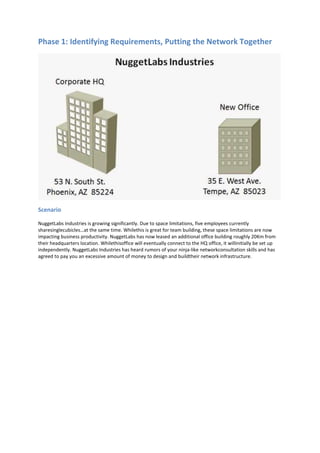
  • 1. Phase 1: Identifying Requirements, Putting the Network Together Scenario NuggetLabs Industries is growing significantly. Due to space limitations, five employees currently sharesinglecubicles…at the same time. Whilethis is great for team building, these space limitations are now impacting business productivity. NuggetLabs has now leased an additional office building roughly 20Km from their headquarters location. Whilethisoffice will eventually connect to the HQ office, it willinitially be set up independently. NuggetLabs Industries has heard rumors of your ninja-like networkconsultation skills and has agreed to pay you an excessive amount of money to design and buildtheir network infrastructure.
  • 2. Gathering Information To help guide this initial configuration, you‘ve assembled a list of requirements based on various meetings with management. The new office will initially house 75 employees, each with their own Cisco IP Phone and PC. This office may eventually scale to 200 employees over 5 years. The Windows admins are planning to install a new pair of redundant servers at the new office. They plan to manage all the IP addresses for DHCP on these servers and are waiting for you to tell them what IP address range they should use. o Windows admins: Jeff Service - (602) 555-1293, Mike Pack (480) 555-9382. The new office is a two story building with the Main Distribution Frame (MDF) in the northwest corner of the first floor. Because of a workman’s strike, poor planning, and other human issues, the Intermediate Distribution Frame (IDF) on the second floor was installed in the southeast corner of the second floor, beyond the reach of typical Ethernet standards. The majority of the employees (roughly 50) will sit on the main floor while the remainder will sit on the second floor. The building contractor has already run the cabling - a single Cat6 Ethernet connection to each cubical / office space which terminates to patch panels in the MDF/IDF area. NuggetLabs is planning to use a Voice over IP (VoIP) phone system for the new office. Each user will have an assigned IP Phone in their cubical / office space. The installation / management of the phone system itself will be the responsibility of another company; however, the network should be prepared to support the additional devices. The new office will need WIFIimplementations, soto keep budgets in checkthe company would liketo use off-the-shelf Cisco Small Business WAPs. These WAPs are to host two wirelessnetworks: NL-CORP and NL- PUB. Those connecting to NL-CORP should have access to the corporatenetwork and resources. Of course, high-end security is mandatory for this wireless network. Thoseconnecting to NL-PUB should not be prompted for any security requirements but should be limitedto Internet access only. NuggetLabs Industries would like you to assess the network and make recommendations on Internetconnectivity options. They would also like to begin evaluating network connections between theiroffices. During the discussions, NuggetLabs Industries found that you work primarily from your home office.Because of the value NuggetLabs places on your technical prowess, they have offered to provide anoffice space located in the MDF for you to use as a lab environment; a "home-away-from-home” youcan use. However, this lab environment must be completely isolated from the corporate network to not cause any interference to day-to-day operations. Priority Client Task Time Assigned 1 NL Initial Meeting with NL Corporate Create initial questionnaire for on-site visit 30 Discuss upcoming branch office rollout (goals, staff involvement, key contacts) 180 1 NL Create NL Proposal Requirements Document 15 Equipment Order 240 VLAN / Subnet List 30 Switchport Connections 30 Physical Visio Diagram 30 Logical Visio Diagram 30
  • 3. Objective Based on this information, NuggetLabs Industries would like you to create a proposal, design, and implementation plan for their new office by next Friday. The submission should include the following elements: Requirements Document Equipment Order VLAN(s) - Necessary IP Subnet(s) - Necessary Switch Port Connections Any Necessary Visio Diagrams Requirements Document Based on company meeting, November 28th, 2011 Attendees Bob Phaman [CEO - BobP@nuggetlabs.com – (602) 555.2791] Sarah Belittle [CTO - SarahB@nuggetlabs.com –(602) 555.8329] Jeff Service[Windows Admin Lead - .JeffS@nuggetlabs.com –(602) 555.1293] Mike Pack [Desktop Support - MikeP@nuggetlabs.com – (480) 555.9382] Grapler Construction Company (various reps) [support@grapler.com] Requirements Network must initially handle 75 users between two floors Network must handle both VoIP and Data traffic Network should handle public(unsecure) and private (secure)WIFI Private office / lab area created in MDF, separate from the network Suggest optionsforInternet connectivity Assumptions Each user will have one workstation Each user will haveoneIP phone Network should handle 1 Gbps Ethernet connectionstothe desktop Dual fiberopticcabling run completed from MDF to IDF Internet connectivity options will be suggested, agreed upon, and installed before the move in date Allcable runsterminatetotheIDF or MDF Each cubical/office will have at least one Cat6Ethernet connection JeremyC Consulting Inc. will be ordering all necessary equipment and patch cables for the operation Windows servers willhave redundantconnections IDF will be initially set up with a 48 port switch (allowing approx. 48% growth) MDF will be initially set up with two48 port switches(allowing approx. 44% growth) PCs and IP Phones will be located no more than 3m from the wall connection, 1.5-2m on average. Single Internet router (no redundancy) is acceptable Single core L3 switch (no redundancy) is acceptable PSTN callingforVoIP network will be handled via SIPTrunk over the Internet MDF and IDF have sufficient powerand coolingforthe equipmentto be installed
  • 4. Phase 1: Brainstorming Requirements Two stories o First Floor MDF - initially housing 50 users, servers, etc... o Second Floor lDF - initially housing 25 users WIFI o Full coverage for first and second floor o Need to perform a wireless site survey (onsite) o Power over Ethernet switches or couplers VoIP o IP Phone per cubical / office o Need additional 1.5-3m Cat 5E / 6 Ethernet cabling as PC patch Priority Client Task Time Assigned 2 NL Onsite Visit WiFi Site Survey 120 Get with Windows guys to determine cabinet 60 Items Needed MDF - two 48-port PoE switches, one of them should be Layer 3 capable o Cisco LAN Access Switches o Cisco 2960 Model Comparison o Cisco 3750-X Model Comparison o First Choice L2 Switch - WS-C2960S-48FPS-L  48-port, L2 switching  740W PoE (15W per port)  (4) 1G SFP Uplinks o First Choice L3 Switch - WS-C3750X—48PF-S  48-port, L3 Switching  740W PoE (1.5W per port)  (4) 1G SFP Uplinks o Mounting- wall mount? Server cabinet? (determine server needs) o Cabling- need plenty of spare 1.5m, 2m, and 3m cables for cubicles. Offices, server connections o Fiberopticconnection: Patch cables and two SFPs MDF - one Internet router o Cisco Routers o Cisco 2900 Series o First Choice Router — Cisco 2901  (2) 1 Gbps built-in interfaces  (4) card slots (expansion using serial, ethernet, etc...)  Voice capabilities (on-board DSPs) IDF - one 48-port PoE switch o First Choice L2 Switch - WS-C2960S-48FPS-L  48-port, L2 switching  740W PoE (15W per port)  (4) 1G SFP Uplinks Building - Wireless access points o Cisco Small Business WIFI options o First Choice - WAP4410N  802.11n/g/b  1Gbps, PoE Capable (802.3af)  Supports4 VLANs, 4 SSlDs
  • 5. Equipment List Name Device Function Location T1 1G 10G NL-B1-SW1 3750X Core L3 Switch MDF 48 NL-B1-SW2 2960S L2 Switch MDF 48 NL-B1-SW3 2960S L2 Switch IDF 48 NL-B1-RT1 2901 Internet Router MDF 2 NL-B1-WI1 WAP4410N WiFi Access Point Ceiling 1 NL-B1-WI2 WAP4410N WiFi Access Point Ceiling 1 NL-B1-WI3 WAP4410N WiFi Access Point Ceiling 1 Name Device Qty Function T1 1G 10G NL-B1-SW1 WS-C3750X-48PF-S 1 Core L3 Switch 48 4 Port Gigabit SFP C3KX-NM-1G 1 4 Redundant PSU C3KX-PWR-715WAC 1 SMARTnet 1 Fibre SFP (SX) GLC-SX-MM 4 Rack Mount Kit C3KX-RACK-KIT 1 IP Addressing Scheme Network Mask VLAN Description 10.1.1-63.0 255.255.192.0 Corporate Office 10.1.64.0 255.255.254.0 VLAN 64 Client VoIP 10.1.65.0 10.1.66.0 255.255.254.0 VLAN 66 Client Data 10.1.67.0 10.1.68.0 255.255.255.0 VLAN 68 Server 10.1.69.0 255.255.255.0 VLAN 69 Public WiFi 10.1.70.0 255.255.255.0 VLAN 70 Lab 10.1.71.0 255.255.255.0 VLAN 71 Network Management 107.20.176.240 255.255.255.240 VLAN 10 Internet DMZ Branch 1 Summary: 10.1.64.0/21 (255.255.248.0) VLAN 64 – Client VoIP IP Address Mask VLAN Description 10.1.64.0 255.255.254.0 64 Client VoIP Network 10.1.64.1 NL-B1-SW1 VLAN 64 IP (Default Gateway) 10.1.64.2-10 Reserved 10.1.64.11 to 10.1.65.245 Client VoIP DHCP Scope 10.1.65.246-254 Reserved 10.1.65.255 Client VoIP Broadcast VLAN 66 – Client Data IP Address Mask VLAN Description 10.1.66.0 255.255.254.0 66 Client Data Network 10.1.66.1 NL-B1-SW1 VLAN 66 IP (Default Gateway) 10.1.66.2-10 Reserved 10.1.66.11 to 10.1.67.245 Client Data DHCP Scope 10.1.67.246-254 Reserved 10.1.67.255 Client Data Broadcast
  • 6. VLAN 68 – Server IP Address Mask VLAN Description 10.1.68.0 255.255.255.0 68 Server Network 10.1.68.1 NL-B1-SW1 VLAN 68 IP (Default Gateway) 10.1.68.2-5 Reserved 10.1.68.6 NL-B1-DC01 10.1.68.7 NL-B1-DC02 10.1.68.8 NL-B1-CUCMBE … 10.1.68.251-254 Reserved 10.1.68.255 Server Broadcast VLAN 71 – Network Management IP Address Mask VLAN Description 10.1.71.0 255.255.255.0 71 Management Network 10.1.71.1 NL-B1-SW1 10.1.71.2 NL-B1-SW2 10.1.71.3 NL-B1-SW3 10.1.71.4 NL-B1-RT1 10.1.71.5 NL-B1-WI1 10.1.71.6 NL-B1-WI2 10.1.71.7 NL-B1-WI3 10.1.71.255 Management Broadcast VLAN 10 – Internet DMZ IP Address Mask VLAN Description 107.20.176.240 255.255.255.240 10 DMZ Network 107.20.176.241 ISP Gateway 107.20.176.242 NL-B1-RT1 External IP (Fa0/0) 107.20.176.243 Unused 107.20.176.244 Unused 107.20.176.245 Unused 107.20.176.246 Unused 107.20.176.247 Unused 107.20.176.248 Unused 107.20.176.249 Unused 107.20.176.250 Unused 107.20.176.251 Unused 107.20.176.252 Unused 107.20.176.253 Unused 107.20.176.254 Unused 107.20.176.255 DMZ Broadcast
  • 7. Port List NL-B1-SW1 Physical VLAN / TRUNK / IP Remote Device Remote Interface Notes G0/1 Trunk NL-B1-SW2 G0/1 EtherChannel 1 2 Trunk NL-B1-SW2 G0/2 EtherChannel 1 3 V10 ISP - CCT ID 392021 4 V10 NL-B1-RT1 G0/0 External Interface 5 V10 Reserved 6 V10 Reserved 7 V68 NL-B1-DC01 LAN1 Windows Server 2008 R2 8 V68 NL-B1-DC02 LAN1 Windows Server 2008 R2 9 … NL-B1-SW2 Physical VLAN / TRUNK / IP Remote Device Remote Interface Notes G0/1 Trunk NL-B1-SW1 G0/1 EtherChannel 1 2 Trunk NL-B1-SW1 G0/2 EtherChannel 1 3 V68 Reserved 4 V68 Reserved 5 V68 Reserved 6 V68 Reserved 7 V68 NL-B1-DC01 LAN2 Windows Server 2008 R2 8 V68 NL-B1-DC02 LAN2 Windows Server 2008 R2 9 V64v,66d Client NIC 10 V64v,66d Client NIC …
  • 9. Phase 2: Configuring the Switch Infrastructure Scenario All the equipment you suggested has been purchased, delivered, and installed at the NuggetLabs branch office facility. You must now begin with the configuration of the switch infrastructure based on the following requirements. Note: VLAN Database mode must be used to configure any VLANs on the switches Hint: NL_B1_SW1#vlan database
  • 10. Requirements To help guide this initial configuration, you've assembled a list of requirements. Each switch will need a base configuration, which includes: o Hostname o Passwords (CON, VTY, Enable) should be set to cisco o Logon banner o Three hour console port timeout o Synchronous logging on the console port o Telnet / SSH enabled (use nuggetlabs.com as your domain and admin/cisco for SSH credentials) o HTTP management disabled o DNS name resolution set to 4.2.2.2 and 4.2.2.3 o Clock set, NTP configured (use 64.73.32.135 as the NTP sewer) o Management VLAN / IP address (use the following table) VLAN 71 – Network Management IP Address Mask VLAN Description 10.1.71.1 255.255.255.0 71 NL-B1-SW1 10.1.71.2 255.255.255.0 71 NL-B1-SW2 10.1.71.3 255.255.255.0 71 NL-B1-SW3 Configure the necessary VLANs on SW1, SW2, and SW3.If a VLAN is not necessary on a switch, it should not be configured. o VLAN 64: Client Voice o VLAN 66: Client Data o VLAN 68: Server o VLAN 69: Public WIFI o VLAN 70: Private LAB o VLAN 71: Management o VLAN 10: Internet DMZ NL-B1-SW1 NL-B1-SW2 NL-B1-SW3 All VLANs VLAN 64, 66, 69, 71 VLAN 64, 66, 69, 71 Configure Etherchannel connections between (SW1 and SW2) and (SW1 and SW3). Use GNS3 to determine appropriate physical connections. The Etherchannel should be hardcoded as ON (does not use any LACP or PAGP negotiation). Configure the links between the switches to forward traffic for all necessary VLANs. lf a VLAN does switch, the trunk should not forward traffic for it. Assign the necessary ports to VLANs based on the following table. Port NL-B1-SW1 NL-B1-SW2 NL-B1-SW3 Fa1/0 Trunk Trunk Trunk 1 Trunk Trunk Trunk 2 Trunk VLANs 64, 66 (Client) VLANs 64, 66 (Client) 3 Trunk VLANs 64, 66 (Client) VLANs 64, 66 (Client) 4 – 13 VLAN 68 (Server) VLANs 64, 66 (Client) VLANs 64, 66 (Client) 14 VLAN 70 (Lab) VLANs 64, 66 (Client) VLANs 64, 66 (Client) 15 Routed Port VLANs 66, 69, 71 (WAP) VLANs 66, 69, 71 (WAP) Create a routed interface on NL-B1-SW1 for each of the VLANs. This interface should be assigned the first IP address from each of the VLAN subnets listed in the following table. Ensure each interface is functional (not shut down). Note: The 10.1.254.0/30 subnet should be configured as a routed interface on F1/15
  • 11. Network Mask VLAN Description 10.1.64.0 255.255.254.0 VLAN 64 Client VoIP 10.1.65.0 10.1.66.0 255.255.254.0 VLAN 66 Client Data 10.1.67.0 10.1.68.0 255.255.255.0 VLAN 68 Server 10.1.69.0 255.255.255.0 VLAN 69 Public WiFi 10.1.70.0 255.255.255.0 VLAN 70 Lab 10.1.71.0 255.255.255.0 VLAN 71 Network Management 10.1.254.0 255.255.255.252 n/a Point-to-Point Configure NL_B1_SW1 as the root of the Spanning Tree network for all VLANs. Enable all interfaces not being used for a switch uplink for Portfast. Configure the Server and PC with the following configuration: Server PC1 PC2 Interface: NIC NIC NIC IP Address: 10.1.68.50 10.1.66.50 10.1.66.51 Gateway: 10.1.68.1 10.1.66.1 10.1.66.1 Testing o PC1 should be able to ping PC2 o PC1 and PC2 should both be able to perform a ping and traceroute to the Server o The show spanning-tree output should reveal that NL_B1_SW1 is the root bridge o You should be able to Telnet and SSH to each switch, PC, or Server using the management interface IP
  • 12. Phase 3: Configuring the Internet Connection and VPN Tunnel Scenario Following your advice, the NuggetLabs branch office has installed a 50Mbps Digital Subscriber Line (DSL) connection. They will be using a VPN connection to connect back to the corporate office.
  • 13. Requirements To help guide this initial configuration, you’ve assembled the following list of objectives: The NuggetLabs branch office router (NL_B1_RT1) needs a base configuration which includes the following: o Hostname o Passwords (CON, VTY, AUX, Enable) should be set to cisco o Logon banner o Three hour console port timeout o Synchronous logging on the console port o Telnet / SSH enabled (use nuggetlabs.com as your domain and admin/cisco for SSH credentials) o HTTP management disabled o DNS name resolution set to 4.2.2.2 and 4.2.2.3 o Clock set, NTP configured (use 64.73.32.135 as the NTP server) The IP addresses for NL_B1_RT1 should be configured as follows: Fa 0/0 Fa 0/1 10.1.254.2 / 30 172.30.100.230 / 24 Configure a static default route on NL_B1_RT1 using the IP address of the ISP router (172.30.100.1) to reach the Internet. Once this default route is in place, NL_B1_RT1 should be able to ping Internet address (i.e. 4.2.2.2, 8.8.8.8) Configure a static default route on NL_B1_SW1 using the inside IP address of NL_B1_RT1 to reach the Internet. Configure NAT in such a way that the following requirements are met: o Subnets provisioned for the branch office are able to reach the Internet using a pool of public BP addresses from 172.30.100.231 to 172.30.100.235 (simulated public for purposes of the lab). o NOTE: NAT should be configured so only the specific subnets at the Branch office are processed by NAT on NL_B1_RT1 o The email server (10.1.68.S0) is reachable from the public IP address 172.30.100.236. Testing - at this point. you should be able to accomplish the following: o Ping the Internet address 4.2.2.2 or 8.8.8.8 from any device in the NL branch network (test using PC1) o Verify NAT entries appear for the connections oh NL_B1_RT1 o Telnet to the Server (10.1.68.50) from its public IP address (172.30.101.236) from the corporate office (NL_CORP_RT1). NOTE: Since the server does not have a VTY password configured, the message, "Password required but none set" is expected and indicates a successful test.
  • 14. Configure a VPN connection between the NuggetLabs branch office facility and the corporate site using the following information (NOTE: this is beyond the current CCNA exam requirements; you will need to configure both NL_B1_RT1 and NL_CORP T1 for this exercise): o Interesting traffic: all subnets at both offices should forward over the VPN connection o Pre-shared key between sites: CBTNuggets-Key!!! o Phase 1 (ISAKMP) Settings:  Encryption: AES-128  Hashing: SHA1  Protection: DH2 o Phase 2 (IPSEC) Settings:  Encryption: AES-128  Hashing: SHA1  No PFS o NAT: Be sure to adjust NAT appropriately for the VPN connection Testing o NL_B1_SW1 should be able to ping any of the VLAN interfaces on NL_CORP_SW1 including:  VLAN 2: CORP_VOICE (10.1.2.1)  VLAN 3: CORP_DATA (10.1.3.1) o NL_CORP_SW1 should be able to ping any of the VI.AN interfaces on NL_B1_SW1 including:  VLAN 64: Client VOICE (10.1.64.1)  VLAN 66: Client DATA (10.1.66.1)
  • 15. Phase 4: Routing Using OSPF Scenario Now that the NuggetLabs branch facility Internet and VPN connection is functional, you would like to implement OSPF routing between both offices. Because NuggetLabs is a growing organization, you intend to design their OSPF network for scalability, implementing the corporate office as the backbone and their first branch office as a different area (which allows for summarization in the network). NOTE: To stay (somewhat) within CCNA Exam requirements, assume the ISP has created a private, MPLS connection on the 172.30.100.0/24 network between the NuggetLabs Branch Office and the NuggetLabs Corporate Office.
  • 16. Requirements To help guide this configuration, you’ve assembled the following list of objectives: Configure the NuggetLabs corporate office to support OSPF o The NL_CORP_RT1 router (the OSPF ABR) should use the Router- o OSPF should run on both NL_CORP_RT1 and NL_CORP_SW1 (Router ID 1.1.1.2).1 o All VLAN interfaces on NL_CORP_SW1 should be configured as passive with the exception of VLAN 1. o All networks internal to the corporate office should be in Area 0. Networks connecting to the branch office should be in Area 1. o Devices should use secure (hashed) OSPF authentication to ensure rogue devices cannot join as an OSPF neighbor. Use the password "cisco" when forming all neighbor relationships. Only non-passive interfaces need be configured for OSPF authentication. o Use only one OSPF network statement with an exact wildcard mask to advertise the corporate network. Use one additional OSPF network statement with a wildcard mask of 0.0.0.0 to form neighbors in Area 1. Configure the NuggetLabs branch office to support OSPF. o The NL_B1_RT1 router should use the Router ID 1.1.2.1. o OSPF should run on both NL_B1_RT1 and NL_B1_SW1 (Router ID 1.1.2.2). o All networks in use at the branch office should be in Area 1. You may not use network commands under the OSPF routing process to advertise these networks. o All VLAN interfaces on NL_B1_SW1 should be configured as passive with the exception of F1/15. o Devices should use secure (hashed) OSPF authentication to ensure rogue devices cannot join as an OSPF neighbor. Use the password "cisco" when forming all neighbor relationships. Only non-passive interfaces need be configured for OSPF authentication. Testing o Verify OSPF neighbors have formed between all relevant Cisco devices o Verify all OSPF - appear on all relevant Cisco devices Advertise a default route from both routers o Remove the static default route from both NL_B1_SW1 and NL_CORP _SW1 o Configure NL_B1_RT1 and NL_CORP_RT1 to advertise a default route unconditionally to NL_B1_SW1 and NL_CORP_SW1. o Verify an OSPF default route now exists on both L3 switches. On the OSPF ABR, configure two-way summarization o The corporate office should summarize all internal, Area 0 networks into a single route when advertise to other OSPF areas. o Devices internal to the corporate office should receive a single, summarized branch office routerepresenting all internal branch office networks (with the exception of the 10.1.254.0/30 link between NL_CORP_SW1 and NL_CORP_RT1). Optimize OSPF o Ensure NL_CORP_RT1 and NL_B1_RT1 become the designated OSPF router for their respective Ethernet segments. NL_CORP_SW1 and NL_B1_SW1 should be exempted from the DR election completely. o Use an OSPF hello timer of 1 second between all OSPF neighbors.
  • 17. Phase 5: Routing Using EIGRP Scenario You have just completed your OSPF configuration. To your dismay, one of the other Microsoft Windows technicians at NuggetLabs has begun to learn Cisco technology by taking courses from CBTNuggets. Apparently, one of the CBTNuggets instructors mentioned that EIG RP is the "best routing protocol in the world”. The NuggetLab technician has taken this heart and has convinced NuggetLabs management to use EIGRP rather than OSPF. They would now like you to convert your OSPF configuration to EIGRP using ideal parameters. NOTE: To stay (somewhat) within CCNA Exam requirements, assume the ISP has created a private, MPLS connection on the 172.30.100.0/24 network between the NuggetLabs Branch Office and the NuggetLabs Corporate Office.
  • 18. Requirements To help guide this configuration, y0u’ve assembled the following list of objectives: Remove all OSPF configuration from NL_CORP_RT1, NL_CORP_SW1, NL_B1_RT1, and NL_B1_SW1. o Configure the NuggetLabs corporate office to support EIGRP o EIGRP should run in autonomous system 7 on both NL_CORP_RT1 and NL_CORP_SW1 advertising all corporate networks o EIGRP should not use automatic summarization o All interfaces on NL_CORP_RT1 and NL_CORP_SW1 should be set as passive with the exception of WAN interfaces and interfaces in VLAN1. o Devices should use secure EIGRP authentication to ensure rogue devices cannotjoin as an EIGRP neighbor. Use the password "cisco" when forming all neighbor relationships. It is not necessary to configure authentication on passive interfaces. Configure the NuggetLabs branch office to support EIGRP. o EIGRP should run autonomous system 7 on both NL_B1_RT1 and NL_B1_SW1. o EIGRP should not use automatic summarization o All networks in use at the branch office should be added to the EIGRP routing process. o All interfaces on NL_B1_$W1 should be set as passive with the exception of the interface used to communicate with NL_B1_RT1. o Devices should use secure EIGRP authentication to ensure rogue devices cannot join as an EIGRP neighbor. Use the password "cisco" when forming all neighbor relationships. It is not necessary to configure authentication on passive interfaces. Testing o Verify EIGRP neighbors have formed between all relevant Cisco devices o Verify all EIGRP routes appear on all relevant Cisco devices Advertise a default route from both routers o Configure NL_B1_RT1 and NL_CORP_RT1 to advertise a default route using redistribution to NL_B1_SW1 and NL_CORP_SW1. o Verify an EIGRP default route now exists on both L3 switches. Configure two-way summarization using NL_B1_RT1 and NL_CORP_RT1 o The corporate office should summarize all internal networks as a single route when advertising to the branch office. o The branch office should summarize all internal networks as a single route when advertising to the corporate office.
  • 19. Phase 6: Services and Security Scenario The NuggetLabs Branch rollout is successful! All devices are communicating the way they should across the network. As the final phase of the implementation, you need to engage DHCP services for the VLAN. In addition, you must now rollout security to protect the Voice VLAN and server VLANs.
  • 20. Requirements To help guide this configuration, you’ve assembled the following list of objectives: For testing purposes, assign PC1 to the voice VLAN (64) while keeping PC2 assigned to the data VLAN (66) Configure NL_B1_SW1 as a DHCP server for the branch office network using the following parameters: o VLANs 64, 66, 69, and 70 should support DHCP services o In the initial testing phase, each VLAN should initially support DHCP assigned addresses from the range 10.1.X.10 - 10.1.X.100 with the correct subnet mask and default gateway. o The voice VLAN should also support DHCP Option 150 (TFTP) to the address 10.1.68.8. o All devices should use 4.2.2.2 and 4.2.2.3 as their primary and secondary DNS server respectively. o Once you have configured DHCP, configure PC1 and PC2 as DHCP clients and verify they receive the expected IP address assignment. Configure the following security restrictions for the branch office: o The Voice VLAN (64) should only be able to access (all else is restricted):  The NuggetLabs Corporate voice subnet (10.1.1.0/24)  The Voice VLAN default gateway (10.1.64.1)  The Internet o The Data VLAN (66) should only be able to access (all else is restricted):  10.1.68.6 (Full Access - NL—B1-DC01)  10.1.68.7 (Full Access - NL—B1-DC02)  10.1.68.8 (TCP 21, 80, 443 - NL-B1-WEBO1)  The Data VLAN default gateway (10.1.66.1)  The Internet o The Public WIFI VLAN (69) and Private Lab VLAN (70) should only be able to access (all restricted):  Their default gateways  The Internet Testing o From PC1 (VLAN 64)  Ping 10.1.64.1 (Voice VLAN gateway - should succeed)  Ping 10.1.66.1 (Data VLAN gateway - should fail)  Ping 10.1.1.1 (Corporate Voice VLAN gateway - should succeed)  Ping 4.2.2.2 (Internet DNS server - should succeed) o From PC2 (VLAN 66)  Ping 10.1.64.1 (Voice VI.AN gateway -should fail)  Ping 10.1.66.1 (Data VLAN gateway - should succeed)  Ping 10.1.1.1 (Corporate Voice VLAN gateway - should fail)  Ping 4.2.2.2 (Internet DNS server - should succeed)  Access TCP port 80 for 10.1.68.6, 10.1.68.7, and 10.1.68.8. The connection will timeout (fail), but the access-Iist should register hits on the corresponding entries. o Move PC1 to VLAN 69 and renew the DHCP-assigned address o From PC1 (VLAN 69)  Ping 10.1.69.1 (Public WIFI VLAN gateway - should succeed)  Ping 10.1.66.1 (Data VLAN gateway - should fail)  Ping 10.1.1.1 (Corporate Voice VLAN gateway - should fail)  Ping 4.2.2.2 (lnternet DNS server - should succeed)
  • 21. Appendix A: Configuring IKE Documentation: 1. Document your IKE Phase 1 negotiation criteria (example below)  Encryption algorithm: AES-128  Hashing: SHA-1  Authentication: pre-shared  Key exchange: Diffie-Hellman Group 2 2. Document your IPSec (IKE Phase 2) negotiation criteria (example below)  Encryption algorithm: esp-aes 128  Authentication: esp-sha-hmac Configuring IKE Phase 1: 1. Enable ISAKMPE crypto isakmp enable 2. Create ISAKMP Policy crypto isakmp policy 100 encryption aes 128 authentication pre-shared group 2 hash sha 3. Configure ISAKMP Identity crypto isakmpidentity <ip address>|<hostname> 4. Configure pre-shared keys crypto isakmpkey <key> address <rempteip address> Configuring IKE Phase 2: 1. Create transform sets crypto ipsec transform-set <name><methods> crypto ipsec transform-set JEREMY esp-aes 128 esp-sha-hmac 2. Configure IPSec lifetime (optional) crypto ipsec security-association lifetime <secs>|<kbytes> 3. Create mirrored ACLs defining traffic to be encrypted and the traffic expected to be received encrypted 4. Configure IPSec crypto-map crypto map <name><seq>ipsec-isakmp crypto map MAP 100 ipsec-isakmp match address <acl> set peer <remote ipaddr> set pfs<group1|2|5> set transform-set <set> Verify: show crypto isakmp policy