Application Notes - Giga-tronics - Are You Damaging Sensitive Microwave Products - Use Caution with Narrow Pulses
•
0 likes•207 views


Recommended
Recommended
More Related Content
What's hot
What's hot (18)
Similar to Application Notes - Giga-tronics - Are You Damaging Sensitive Microwave Products - Use Caution with Narrow Pulses
Similar to Application Notes - Giga-tronics - Are You Damaging Sensitive Microwave Products - Use Caution with Narrow Pulses (20)
More from Sematron UK Ltd
More from Sematron UK Ltd (14)
Recently uploaded
Recently uploaded (20)
Application Notes - Giga-tronics - Are You Damaging Sensitive Microwave Products - Use Caution with Narrow Pulses
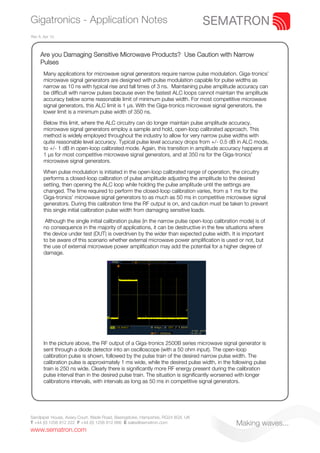
- 1. Gigatronics - Application Notes Rev A. Apr 10. Are you Damaging Sensitive Microwave Products? Use Caution with Narrow Pulses Many applications for microwave signal generators require narrow pulse modulation. Giga-tronics’ microwave signal generators are designed with pulse modulation capable for pulse widths as narrow as 10 ns with typical rise and fall times of 3 ns. Maintaining pulse amplitude accuracy can be difficult with narrow pulses because even the fastest ALC loops cannot maintain the amplitude accuracy below some reasonable limit of minimum pulse width. For most competitive microwave signal generators, this ALC limit is 1 μs. With the Giga-tronics microwave signal generators, the lower limit is a minimum pulse width of 350 ns. Below this limit, where the ALC circuitry can do longer maintain pulse amplitude accuracy, microwave signal generators employ a sample and hold, open-loop calibrated approach. This method is widely employed throughout the industry to allow for very narrow pulse widths with quite reasonable level accuracy. Typical pulse level accuracy drops from +/- 0.5 dB in ALC mode, to +/- 1 dB in open-loop calibrated mode. Again, this transition in amplitude accuracy happens at 1 μs for most competitive microwave signal generators, and at 350 ns for the Giga-tronics’ microwave signal generators. When pulse modulation is initiated in the open-loop calibrated range of operation, the circuitry performs a closed-loop calibration of pulse amplitude adjusting the amplitude to the desired setting, then opening the ALC loop while holding the pulse amplitude until the settings are changed. The time required to perform the closed-loop calibration varies, from a 1 ms for the Giga-tronics’ microwave signal generators to as much as 50 ms in competitive microwave signal generators. During this calibration time the RF output is on, and caution must be taken to prevent this single initial calibration pulse width from damaging sensitive loads. Although the single initial calibration pulse (in the narrow pulse open-loop calibration mode) is of no consequence in the majority of applications, it can be destructive in the few situations where the device under test (DUT) is overdriven by the wider than expected pulse width. It is important to be aware of this scenario whether external microwave power amplification is used or not, but the use of external microwave power amplification may add the potential for a higher degree of damage. In the picture above, the RF output of a Giga-tronics 2500B series microwave signal generator is sent through a diode detector into an oscilloscope (with a 50 ohm input). The open-loop calibration pulse is shown, followed by the pulse train of the desired narrow pulse width. The calibration pulse is approximately 1 ms wide, while the desired pulse width, in the following pulse train is 250 ns wide. Clearly there is significantly more RF energy present during the calibration pulse interval than in the desired pulse train. The situation is significantly worsened with longer calibrations intervals, with intervals as long as 50 ms in competitive signal generators. Sandpiper House, Aviary Court, Wade Road, Basingstoke, Hampshire, RG24 8GX, UK T +44 (0) 1256 812 222 F +44 (0) 1256 812 666 E sales@sematron.com Making waves... www.sematron.com
- 2. Gigatronics - Application Notes Rev A. Apr 10. The best solution to this potential problem (where applicable) is to allow the microwave signal generator to initialise the narrow pulse mode before applying the test signal to the DUT, either manually or by adding a non-reflective switch or a step attenuator between the generator and DUT in an automated test system. In summary, Giga-tronics’ microwave signal generators offer superior pulse modulation performance compared to the competition, allowing very narrow pulses with ALC leveled narrow pulse width operation to 350 ns versus the 1 μs for the competition, and 1 ms calibration interval versus 10 ms to as much as 50 ms for the competition. This difference improves pulse level accuracy and also lessens the possibility of damaging sensitive receivers and devices under test. Sandpiper House, Aviary Court, Wade Road, Basingstoke, Hampshire, RG24 8GX, UK T +44 (0) 1256 812 222 F +44 (0) 1256 812 666 E sales@sematron.com Making waves... www.sematron.com