1. Ansys Workbench 11 Tutorial, Mech 403, November 2007
C Bracket Modeling Tutorial
Introduction
This tutorial is intended to introduce Ansys Workbench 11 by constructing a C‐bracket shown below.
You can open Ansys from within SolidWorks (via Tools Add Ins Ansys 11) or directly:
1. Start Programs Ansys Workbench (which may take about 10 minutes to open) lets you access the
Workbench Start window
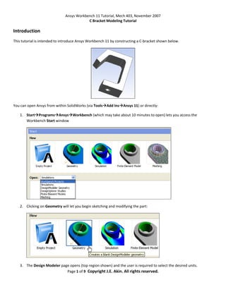
2. Clicking on Geometry will let you begin sketching and modifying the part:
3. The Design Modeler page opens (top region shown) and the user is required to select the desired units.
Page 1 of 9 Copyright J.E. Akin. All rights reserved.
2. Ansys Workbench 11 Tutorial, Mech 403, November 2007
Sketching
4. On the left of the page select Sketching to open the construction Tree Outline
5. In the Tree Outline select the XYPlane for the initial sketch. It opens as an isometric view. Select the Look At
(or Normal To) icon to get the true shape view
6. On the left of the page the Sketching Toolboxes panel appears with the list of line options
Page 2 of 9 Copyright J.E. Akin. All rights reserved.
3. Ansys Workbench 11 Tutorial, Mech 403, November 2007
7. From the list pick Line to begin the input of straight lines outlining the bracket shape. Symbols such as V, and H
appear to denote when the line is vertical or horizontal, etc.
8. To require the two end segments to have the same length select Constraints Equal Length and click on the
two end segments.
9. Begin describing the dimensions to be available as parametric design features with Dimensions General and
select the leftmost vertical edge. The parameter V1 appears as a dimension. The letter means that it is a
vertical line. The value of the actual dimension will be assigned shortly. Note that there are several choices for
dimensions in the Dimensions panel.
Page 3 of 9 Copyright J.E. Akin. All rights reserved.
4. Ansys Workbench 11 Tutorial, Mech 403, November 2007
10. The inclined segment of the bracket does not appear to have parallel sides as desired. To assure that it does
select (on the left of the page) Constraints Parallel and pick the two lines. Note that the Constraints panel has
several common types available for the user.
11. Continue with the remaining length dimensions via Dimensions Horizontal and select the three locations.
12. For the final parameter specify the angle of the inclined leg: Dimensions Angle and pick the inclined line and
the bottom line. Sometimes you will want to right click to specify an Alternate Angle choice.
Page 4 of 9 Copyright J.E. Akin. All rights reserved.
5. Ansys Workbench 11 Tutorial, Mech 403, November 2007
13. At this point the actual parametric dimensions will be input to replace those in the initial sketch. On the left of
the page the Details View panel contains the Dimensions sub‐panel with the default dimension names (V1, L4,
etc) and their as sketched initial values. Click on each value to be changed and type in the desired values. The
sketch changes shape to reflect the new dimension values.
Page 5 of 9 Copyright J.E. Akin. All rights reserved.
6. Ansys Workbench 11 Tutorial, Mech 403, November 2007
Extrusion
14. Having completed the cross‐sectional sketch you are ready to form a solid with an Extrude operation. Note that
icon at the top of the page, along with other construction features like Revolve, Sweep, Loft, etc.
15. Change to an Isometric View (by any of various methods) to be able to see the extrusion normal to the sketch.
16. Pick the Generate icon at the top (this is a frequently used icon) to actually perform the extrusion. A default
extrusion length appears in the isometric view.
17. To specify a desired extrusion length use Details View Details of Extrude 1 and click on Depth and type in the
actual length (here 20 mm).
Page 6 of 9 Copyright J.E. Akin. All rights reserved.
7. Ansys Workbench 11 Tutorial, Mech 403, November 2007
Features
18. The part is almost complete except for interior fillets and the support bolt hole. To create the bolt hole it is
necessary to select one of the two top planes, insert a circle sketch, and cut out the hole. At the page top pick
the Select Face icon, and click on the lower surface (the top would have actually been easier).
19. In the Tree Outline right click on Body Create New Plane. A default new plane name will appear in the tree.
20. Use Sketching Sketching Toolboxes Circle and place the circle near the center of the surface.
Page 7 of 9 Copyright J.E. Akin. All rights reserved.
8. Ansys Workbench 11 Tutorial, Mech 403, November 2007
21. Add the new dimensions with Dimensions Diameter, Dimensions Vertical, Dimensions Horizontal, and
provide the desired values via Details View Dimensions for D1, H2, and V3.
22. To form the cut select the Sketch_name and then Extrude
23. A default extrude length appears. Specify a cut with Details View Operation and right click on Add Material
and change it to Cut Material. Use Details View Extent Type Through All Generate.
Page 8 of 9 Copyright J.E. Akin. All rights reserved.
9. Ansys Workbench 11 Tutorial, Mech 403, November 2007
24. For the fillets, pick the Select Edge filter icon and pick the three interior edges.
25. Form and dimension the fillets Create Fixed Radius Blend followed by Details View Details of FBlend to set
the radius to 3mm and Apply to see the fillets appear and finish the part.
Page 9 of 9 Copyright J.E. Akin. All rights reserved.