Downloaded 1,112 times
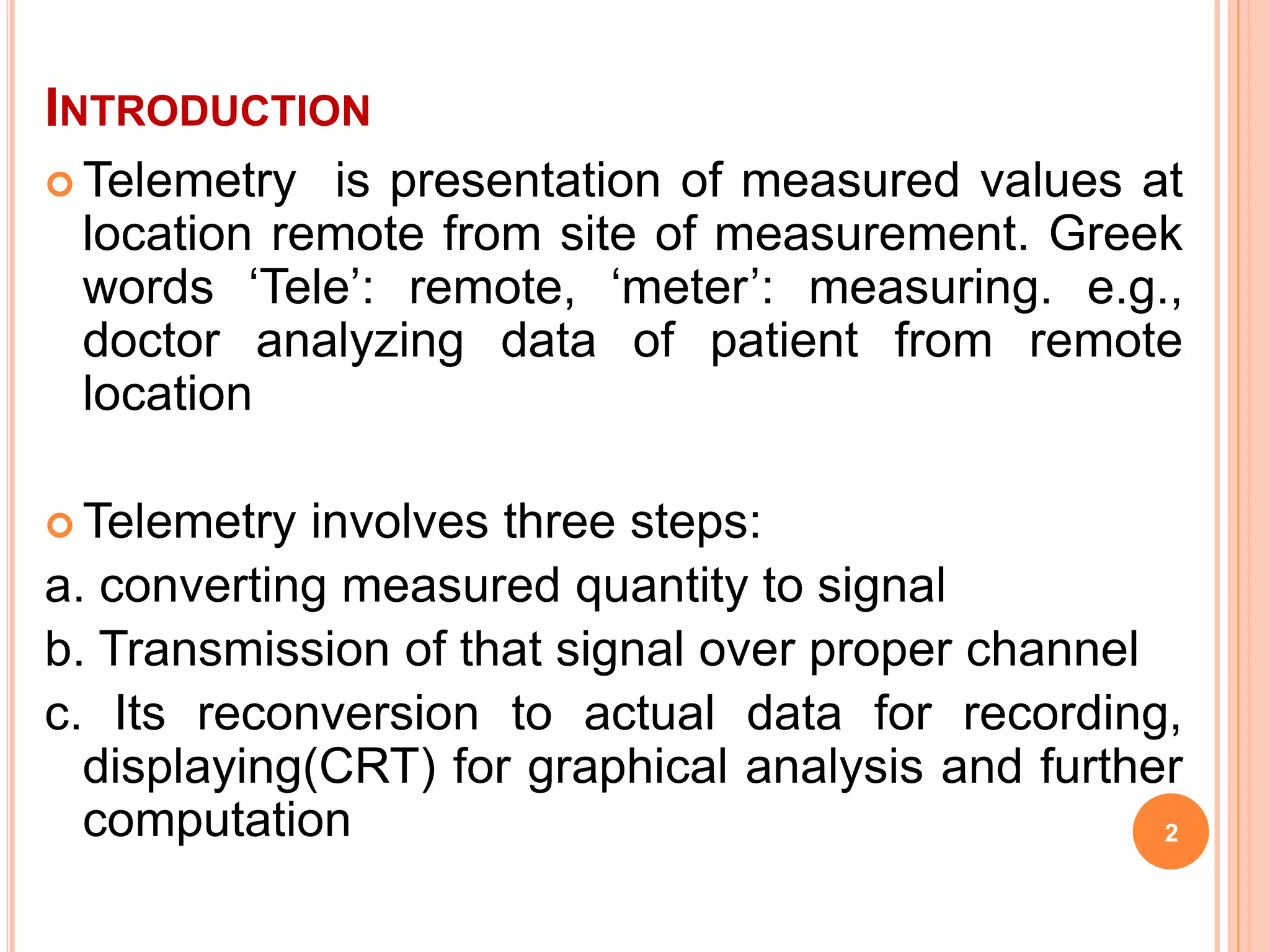
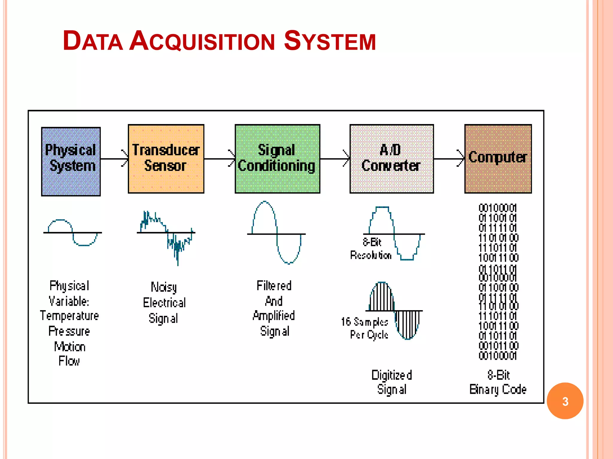
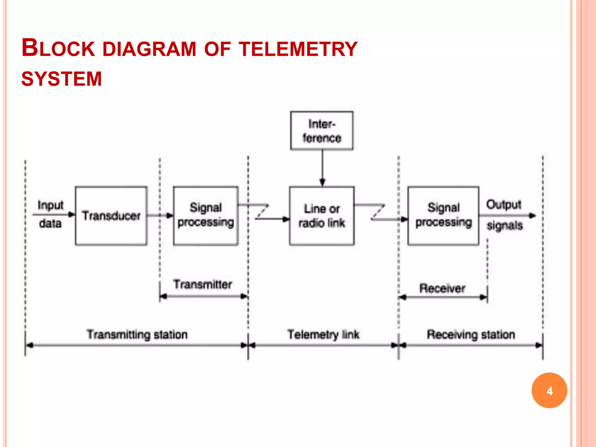
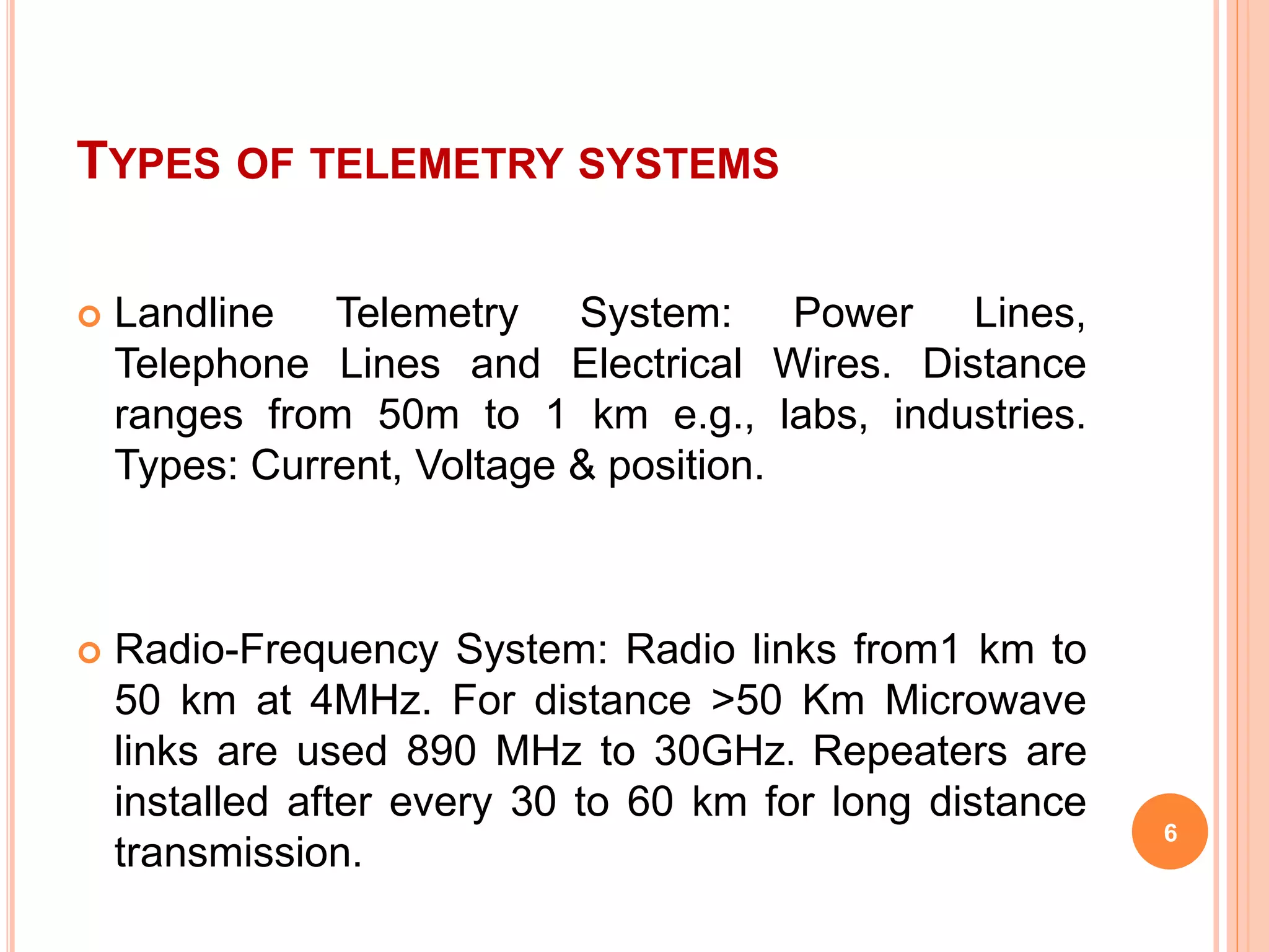
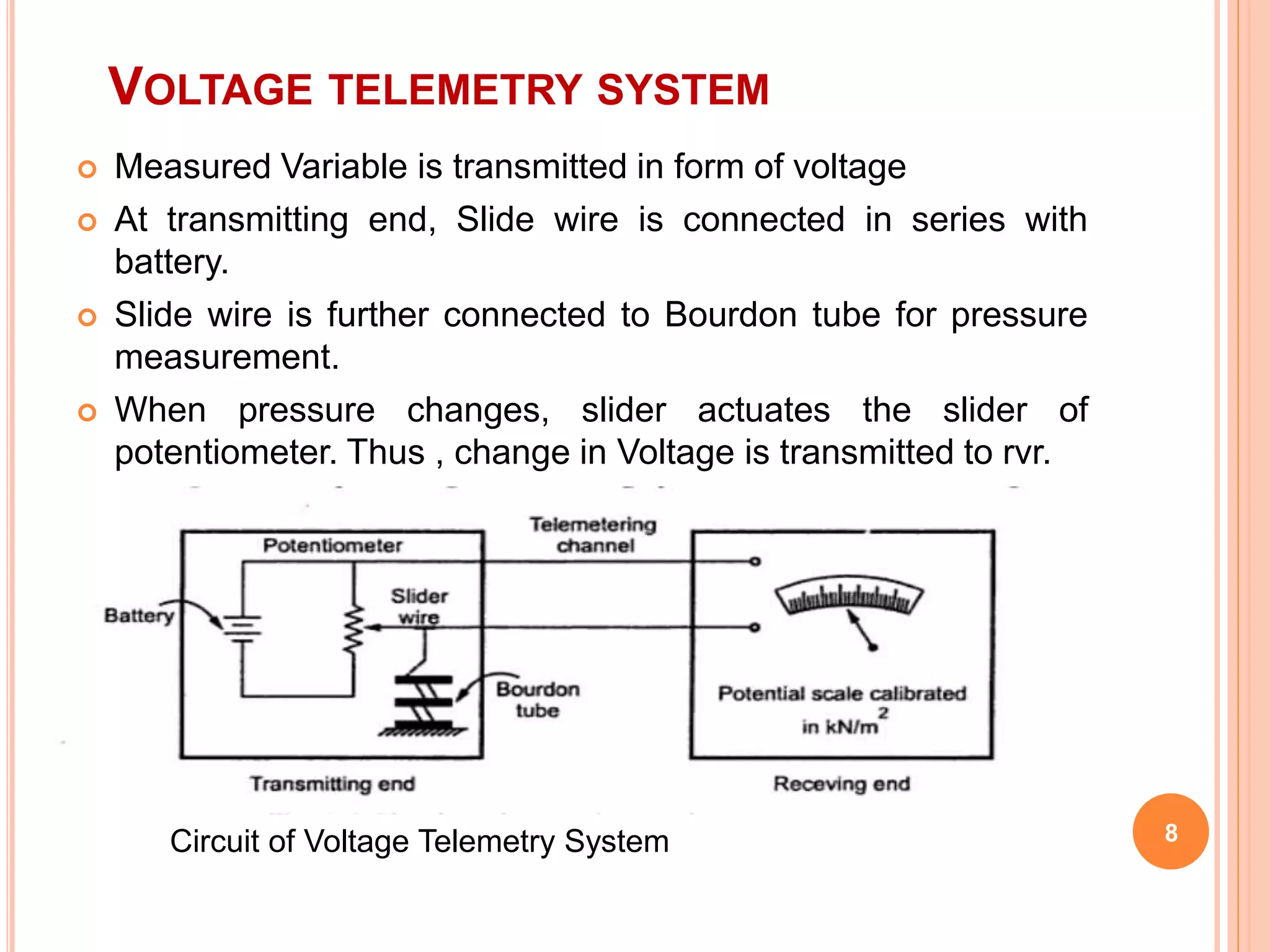

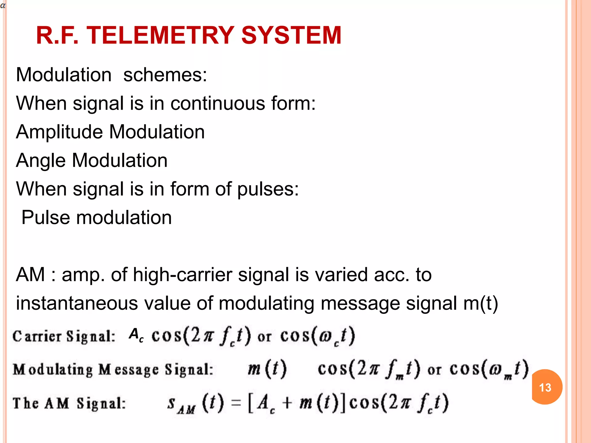
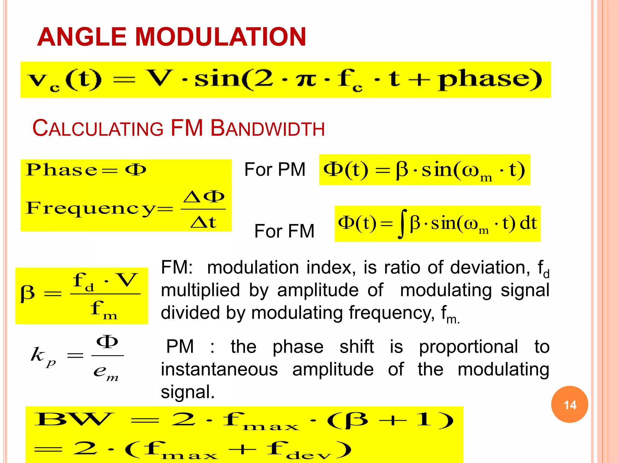
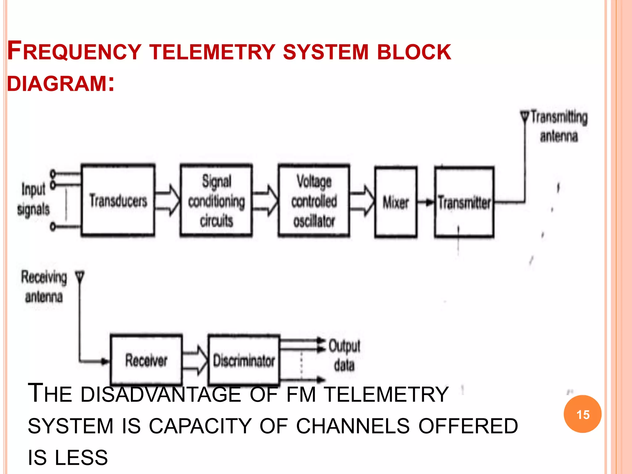
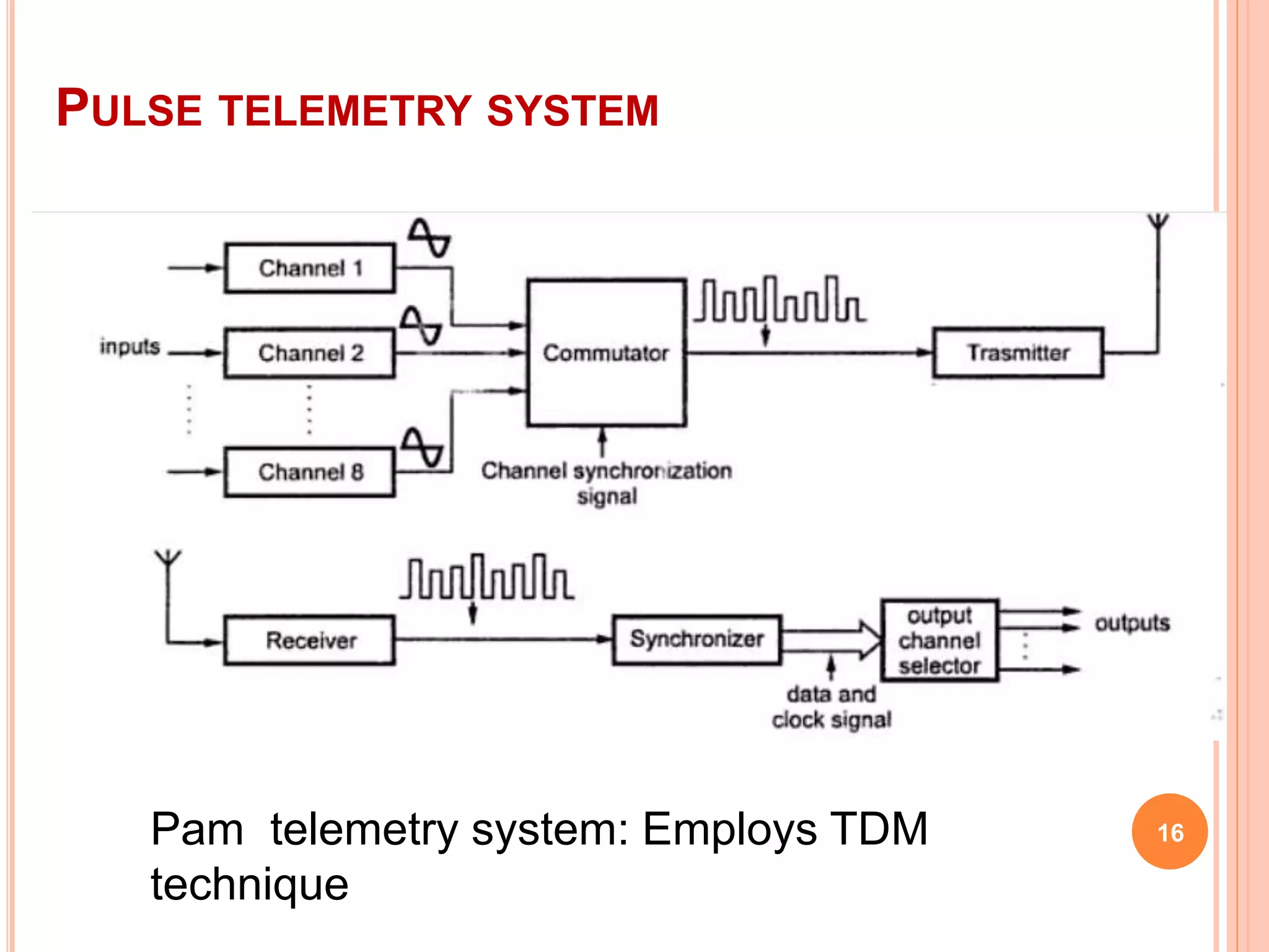

This document discusses telemetry, which is the remote measurement and transmission of data from its source. It involves converting measured values to signals, transmitting those signals over a channel, and reconverting the signals at the receiving end. There are two main types of telemetry systems: landline systems which can transmit over short distances like wires, and radio frequency systems which can transmit over longer distances using radio links. The document provides examples and diagrams of voltage and current landline telemetry systems, as well as discussing modulation techniques like amplitude, frequency, and pulse modulation used in radio frequency systems.