SlideShare a Scribd company logo
1 of 24
Download to read offline
TALAT Lecture 2205


                     Special Design Issues
                                 24 pages, 31 figures

                                     Basic Level

     prepared by Torsten Høglund, Royal Institute of Technology, Stockholm
                Dimitris Kosteas, Technical University, Munich
                                     and
           Steinar Lundberg, Hydro Aluminium Structures, Karmoy


Objectives:

− to describe the measurement and amount of residual stresses in extruded and welded
  profiles which have to be accounted for in design
− to introduce the subject of corrosion and of preventive design measures
− to describe the behaviour and properties of structural aluminium alloys at ambient,
  low and elevated temperatures
− to give useful examples of structural applications of extrusions


Prerequisites:

− background in mechanical and structural engineering disciplines


Date of Issue: 1994
 EAA - European Aluminium Association
2205                Special Design Issues

Table of Contents

2205 Special Design Issues ...................................................................................2
   2205.01 Residual Stresses ....................................................................................... 3
      Introduction..............................................................................................................3
      How to Measure Residual Stresses ..........................................................................4
      Residual Stress in Extruded Profiles........................................................................4
      Residual Stresses in Welded Profiles.......................................................................6
      Residual Stress Effects on Fatigue Behaviour .........................................................8
   2205.02 Corrosion ................................................................................................. 10
      Introduction............................................................................................................10
      Galvanic Corrosion ................................................................................................11
      Differential Aeration Corrosion.............................................................................12
      Design Examples for Avoiding Corrosion.............................................................13
   2205.03 Working Temperature............................................................................. 18
      Mechanical Properties............................................................................................18
      Aluminium Alloy Structures Exposed to low Temperatures .................................19
      Aluminium Alloy Structures Exposed to Elevated Temperatures. ........................20
      Linear Thermal Expansion.....................................................................................20
   2205.04 Using Extrusions in Design .................................................................... 21
   2205.05 References................................................................................................ 23
   2505.06 List of Figures............................................................................................ 23


TALAT 2205                                                          2
2205.01               Residual Stresses

          •      Introduction
          •      How to measure residual stresses
          •      Residual stress in extruded profiles
          •      Residual stresses in welded profiles
          •      Residual stress effects on fatigue behaviour


Introduction

If a part of a structural element has been subjected to non-uniform, plastic deformation,
residual tension and compression stresses will remain which are within the elastic
regime. The sum of internal tension and compression stresses is always zero, if there are
no external forces. The inhomogeneous deformation field which generates residual
stress is caused by processes such as cooling and quenching after extrusion, welding or
cold working, e.g. bending and straightening of profiles.

For a welded T-profile the residual stresses may develop as follows: During
solidification and further cooling the material of the weld zone experiences a larger
shrinkage than the surrounding colder and more rigid base metal due to volume
differences in the liquid and solid states and due to thermal contraction. The larger
shrinkage of the weld zone induces tensile stresses in a magnitude limited by the
momentary yield strength of the material in the warmer weld zone. The contraction of
the weld and heat affected zone induces in turn compressive stresses in the the cross
section of the surrounding colder base material, see Figure 2205.01.01.


                                        Example of Residual Stresses in a Welded T-Profile

                                                                               +

                                                  -


                                                                                                                +


                                                                                                -
                                                      alu

              Training in Aluminium Application Technologies
                                                               Example of Residual Stresses in a Welded T-Profile   2205.01.01


TALAT 2205                                                                               3
How to Measure Residual Stresses

The most common method is the destructive method which is based upon the technique
of cutting the specimen in a number of strips (Figure 2205.01.02). The residual stresses
are calculated from measurements on each strip.

There are two methods of measuring. The first is to measure the length of the strip
before and after cutting it from the section. If Young's modulus is known, it is easy to
apply Hooke's law and determine the residual stress. The second method is to mount
electrical resistance strain gauges on the strips and determine the residual stresses by
applying Hooke's law. This method is the most commonly used one today. Note:
Hooke's law can be applied since residual stresses are essentially within the elastic
range. With the methods stated here only longitudinal residual stresses are determined,
which, however, are of greatest importance from a structural point of view.


Residual Stress in Extruded Profiles

Mazzolani | 1 | shows results from a number of experiments where residual stresses were
determined for different types of profiles. These consist of different alloys and were
manufactured by various processes. The results from experiments on I-profiles are
shown in Figure 2205.01.01 and Figure 2205.01.02.


                            Sectioning a Test Beam For Measuring of
                                       Residual Stresses
                                                                                               b


                                                                                      L0
                                                                       L1


                                                                                           L


                                                            h


                                                  alu           Sectioning a Test Beam For Measuring of
                                                                                                          2205.01.02
           Training in Aluminium Application Technologies
                                                                           Residual Stresses


The results of experiments conducted on I-profiles consisting of four different alloys are
shown in Figure 2205.01.03. The residual stresses seem to be randomly distributed over
a cross section. No simple rule seems to apply to the stress distribution as is the case for
rolled steel sections. Observations show that residual stresses are low, the compressive


TALAT 2205                                                                           4
stresses almost never exceed 20 MPa and tensile stresses are much lower. These values
are measured on the surface of the profiles. At the center of the material the values are
probably even lower, since residual stresses usually change sign from one side to the
other.


                                Residual Stresses in an I-Profile of Different Alloys

                                                                   1   A - U4G ; f0.2 = 40.5 ; ft = 50.7 ; ετ = 13.8
                                                                   2   A - GSM ; f0.2 = 13 ; ft = 28.5 ; ετ = 31
                                                                   3   A - SGM ; f0.2 = 27.6 ; ft = 30.4 ; ετ = 17.7
                                            2                          A - Z5G ; f0.2 = 27.5 ; ft = 34 ; ετ = 10                   4
            +                                                      4                                                   +

                                            1                                                                                      3
            +                                                                                                          +
                                                 +                 +                                                               +          +
                                                                                 Scale: 50 N/mm²

                                                                                            + tension
                                                                                              compression
                                                   1               2                                                                   3          4
            +                                                                                                          +
                                            1                                                                                      3
            +                                2                                                                         +           4


          Source: Mazzolani

                                                 alu
                                                                        Residual Stresses in an I-Profile of Different Alloys              2205.01.03
          Training in Aluminium Application Technologies


The intensity and distribution of residual stresses in aluminium profiles seem to be not
affected by alloy composition.

Figure 2205.01.04 shows the results of experiments on an I-profile at different stages in
the manufacturing process.


                                                       3                                          Alloy 7020
                      +
                                                                                                  1. Extruded and cooled by air
                                                       2
                      +                                                                           2. Extruded and straightened (about 1%)
                                                       1
                                                                                                  3. Extruded, straightened and artificially
                      +
                                                                                                     tempered (100° C for 4 hours and
                                                           +              +           +
                                                                                                     140° C for 24 hours).


                                                               1            2           3
                      +
                                                       1                                                          Scale: 50 N/mm²
                       +                               2                                                                   + tension
                                                                                                                             compression
                       +
                                                       3

         Source: Mazzolani

                                                 alu                     Residual Stresses in I-Profiles for Different
                                                                                                                                           2205.01.04
         Training in Aluminium Application Technologies
                                                                                Manufacturing Processes


TALAT 2205                                                                                           5
The residual stresses for these cases are rather small and seem to change from
compression to tension during refinement. The reduction of residual stresses is due to
the straightening process that the profiles are subjected to during manufacturing. The
remaining residual stresses have a negligible effect on the load bearing capacity.


Residual Stresses in Welded Profiles

In contrast to what has been said for extruded profiles, residual stresses cannot be
neglected in welded profiles. Welding produces a concentrated heat input which causes
the remaining stresses (see above). Large tensile stresses in connection to the web and
balancing compression stresses in other parts are characteristic.

Figure 2205.01.05 shows the results of residual stress measurements for an I-beam
fabricated by welding aluminium plates of different sizes and alloys. Both, heat-treated
and non-heat-treated alloys were used. The resulting differences were very small. The
maximum tensile stress was 90 - 100 N/mm² and the maximum compression stress 30 -
40 N/mm². The lower values correspond to the heat-treated alloy.


                                                                    σr(N/ mm )
                                                                            2


                                                              150
                                                              100
                                                              50
                                                          +
                                                               0
                                                          -
                                                              50
                                                              100


                                                                                                              σr(N/ mm )
                                                                                                                      2
                                                                                    150 100 50 0 50 100 150
                                                              150
                                                                                             +   -
                                                              100

                                                               50
                                                          +     0
                                                          -    50

                                                                     σr(N/ mm )
                                                              100               2
         Source: Mazzolani

                                                alu                 Typical Residual Stress Distribution for a             2205.01.05
         Training in Aluminium Application Technologies             Welded I-Profile Consisting of Flat Plates


Typical residual stress distributions for two different I-profiles are shown in Figure
2205.01.05 and Figure 2205.01.06. The highest values of tensile stress in both cases
were 140 N/mm². The greatest values of compressive stresses were 50 N/mm² except for
the web of the specimen in Figure 2205.01.06 where compressive stresses reached 100
N/mm². An important conclusion reached from these experiments is that welded
connections between extruded profiles should be placed in areas where they cause a
minimum reduction of strength.


TALAT 2205                                                                                 6
These experiments also show that the residual stresses in relation to the yield limit of the
material are much lower for aluminium profiles than for corresponding steel profiles. In
the experiments, the residual tensile stresses were less than 60 % of the 0,2 % proof
stress. For steel residual stresses may be greater than the yield stress of the material. The
residual compressive stresses are typically 20 % for aluminium and 70 % for steel.
Therefore, considering residual stresses, it is more favourable to weld aluminium than it
is to weld steel. However, for aluminium the strength of the material is reduced up to 50
% in the zone around the weld. This counterbalances the effect of the residual stress
distribution.


                                                                       σr(N/ mm )
                                                                                     2
                                                              100
                                                     +          50
                                                     -            0
                                                                50
                                                              100


                                                                                                                                                       σr(N/ mm )
                                                                                                                                                               2
                                                                                                                   150 100 50 0       50 100 150
                                                              100
                                                                                                                             +    -
                                                                50
                                                      +
                                                      -           0
                                                                50
                                                              100
                                                                        σr(N/ mm )
                                                                                         2
             Source: Mazzolani

                                                     alu              Typical Residual Stress Distribution For an I-Profile
                                                                                                                                                             2205.01.06
             Training in Aluminium Application Technologies
                                                                         With Flanges Consisting of Extruded Profiles


In order to take residual stresses into consideration when solving numerical problems.
e.g. in stability problems, the stress distribution is approximated for different cross
sections (Figure 2205.01.07).

                                                                                σr                       σr
                                                                                     f0.2                     fy

                                                                                                              1.0
                                                                          0.6                    +
                                                                          0.2                                 0.7
                                                                                             -       -
                                                                                                                        0.5 0.6       σr
                                                                                                                                           f0.2

                                                                                                                             +


                                                                                                                         -


                                                                                                                             +

                                                                                                                                            σr
                                                                                                                                                  fy
                                                                                                                        0.6 1-1.50
                                                                          Steel Fe 360 (fy = 235 N/ mm2)
                                                                          Alloy 6082 (f0.2 = 235 N/ mm2)

                                                          alu
                                                                        Example of Approximated Residual Stress Distribution                                 2205.01.07
                 Training in Aluminium Application Technologies


TALAT 2205                                                                                                    7
The stress distribution model is convenient when simulating problems by use of
computer calculations.

Normally, a further simplification is adopted. Often the continuous curves are replaced
by equivalent block curves as those shown in Figure 2205.01.08. These curves are
easier and faster to use in numerical models. The last type is the one used for the
determination of load-bearing curves for design regulations.


                                                                                                        σf- = 50 N mm2
                                                                           b = 100mm
                                                                                                        σf = σw = 140 N mm2
                                                                                                          +     +
                                                                   N mm2   χb    χb
                                                                                                        σw =120 N mm2
                                                                                                          -
                                                                    150
                                                                    100

                                                               +
                                                                     50                σf
                                                                                           +
                                                                                                        χ    = 0,30
                                                                      0
                                                                                                        ξ
                                                                                                         h
                                                                   -
                                                                     50                σf
                                                                                         -
                                                                                                             = 0,157
                                                                                                    σ w
                                                                                                       +
                                                                                                             σw
                                                                                                                 -

                                                                    100

                                                                                  12
                                                                                                                         ξh
                                                          200 mm


                                                                                 8
                                                                                                                              h = 176mm


                                                                                                                         ξh

                                                                                                                          N mm2
                                                                                               150 100 50 0 50 100 150
                                                                                                        +    -

                                                alu                Example of the Most Common Way of Determining                          2205.01.08
         Training in Aluminium Application Technologies
                                                                            a Residual Stress Distribution.


Residual Stress Effects on Fatigue Behaviour

Earlier we have already mentioned the difficulties in detecting, measuring or in any way
quantifying the residual stress situation of a structural component. Indirectly, this
situation has been reflected in the proposals for the „fatigue reduction factor“ f(R).

Currently efforts are being undertaken to quantify the residual stress pattern of welded
aluminium constructions. During the course of the drafting of the ECCS-ERAAS
(European Recommendation for Aluminium Alloy Structures) information was used
which was obtained from the comprehensive welded-beam fatigue testing programmes
at the Technical University of Munich (TUM). Residual stress measurements were made
of full-size welded components of 7020 and 5083 alloys, see Figure 2205.01.09.

The measurements themselves and the difficulties associated with the interpretation of
these limited results together with other somewhat contradictory information being
described elsewhere allow presently only the following general conclusions:

− Residual stresses in welded components of aluminium are of considerable magnitude,
  reaching values up to the 0,2 - yield limit of the HAZ, see Figure 2205.01.10


TALAT 2205                                                                                           8
− Scatter is an inherent feature in measurements made by the hole-drilling method.
  Efforts were undertaken to make measurements sufficiently close to the welds,
  approximately 1 mm off the weld toe, by using rosettes with the strain gages arranged
  on one side only.

− There were some but not significant differences in residual stresses in the structural
  details of the 7020 and 5083 alloy.


                                                                                                                                                                                 0
                                                                                                                                                                        B2 •10•27
                                                                                                                                                                          0
                                                                                                                                                                        12


                                                                                                                                                    0
                                                                                                                                           B1 •10•24                                             40
                                                                                                                                                                                                   0
                                                                                                                                                 0
                                                                                                                                               12
                                                                                                                             C4
                                                                                                                      B2                                                           12
                                                                                                                                                                                     00


                                                                                                       C2
                                                                                             C1                                                                   40
                                                                                                                                                                    0         B2

                                                                                                                                                            0
                                                                               C3                                                                         40
                                                                                                                                             0
                                                                     B2                                                                    40
                                                                                                                                                                                                         00
                                                                                                                                     0               B1                                                12
                                                                                                                                   40
                                                                                                                        0
                                                                                                                      40
                                                    B1                                                                      D2 15•300                                                       00
                                                                                                        40
                                                                                                          0                   0•                                                          12
                                                                                                                            15
                                                                                                               1
                                                                                                           / E 350                                                                 40
                                                                                                                                                                                     0
                                                                                                        E2 50•30•
                                                                                                            3                                                             0
                                                                                      00                                                                                40
                                                                                    12        D1 300
                                                                                                5•
                                                                                             0•1
                                                                                           15                                                                   40
                                                                                                                                                                  0


                                                            40
                                                              0           B2                                                                          40
                                                                                                                                                        0

                                                                                                                                           0
                                                                                                                                         40

                                                                                                                              0
                                                                                                                            40
                                                       B1
                                                                                                                  0
                                                                                                                40


                                                                                             00
                                                                                           12


                                                                    00
                                                                  12


         Source: D. Kosteas, Technical University Munich

                                                 alu
                                                                   Welded Aluminium Beams for Fatigue Tests                                                                                                   2205.01.09
          Training in Aluminium Application Technologies


As seen in Figure 2205.01.10 the highest values of residual stresses were recorded at
fillet welded longitudinal or transverse attachments on the beam flanges. Residual
stresses in these details reached values of over 180 MPa. Residual stress measurements
at butt welded splices and cruciform joints made with butt-like full penetration welds
attained values of between 120 and 140 MPa.

No answer can be offered for the time being to the question of whether initially
measured residual stresses are maintained, and at what magnitude, during subsequent
load cycling of the components. Indirect measurements at strain gauge monitored crack
initiation sites showed values up to 120 MPa. These gauges may not have been
sufficiently close to the maximum residual stress site, though. Residual stresses,
therefore, may have been higher.

The generally lower level and steeper slope of S-N curves of full-size components vs.
small specimen data agree with similar findings in steel weldments (see DIN 15015 and
Eurocode 3 or ECCS TC6).

There are still difficulties in interpreting differences between S-N curves with stress
ratios of R = -1 and +0,1. The first show at times approximately 40 % higher fatigue
strength values of stress range plotted in a log-log diagram at two million cycles. The


TALAT 2205                                                                                                                                9
effect is more pronounced in the case of 7020 alloy details. It does not seem prudent,
though, to allow for a bonus in design values in cases of large components, since
sufficiently reliable data is still missing.


            HAZ yield strength design value

                                                               200
                            HAZ
                       R                = 180
                            p0,2

                                                               150
                       R HAZ = 125
                           p0,2
                                                               100
                                   Residual Stress σ z


                                                                50
                                   in tension N/ mm2


                                                                 0
                                                                        B      C1       C2        C3        C4       D1             D2    E
                                                                                                        V        X
                                                                                    X        V          V        X

                                                                               7020              5083
                                                                                                                               σx
                                                                     Residual Stress σ1 = from 1.20 to 1.60 σz            σ1         σz


         Source: D. Kosteas, Technical University Munich

                                                         alu
                                                                 Residual Stresses Measured in Fatigue Test Beams                         2205.01.10
          Training in Aluminium Application Technologies


2205.02                    Corrosion

                •          Introduction
                •          Galvanic corrosion
                •          Differential aeration corrosion
                •          Design examples for avoiding corrosion


Introduction

Aluminium and its alloys are always protected by a film of Al2O3 or Al2O3 · H2O of
various thicknesses due to their large oxygen affinity. Due to this protective film, the
alloys have a good resistance to sea water, most neutral solutions, many weak acid
solutions as well as sulfurated hydrogen, hydrocarbons and carbonic acid. The pH has to
be between 4,5 and 9,0 if inhibitors are not added.

Aluminium is a metal with a large electronegative potential. Contact between
aluminium and more electropositive metals such as copper, lead and steel when


TALAT 2205                                                                                        10
moisture is present, must be avoided. This can be done by using correct electrical
insulation between the two metals, i.e. by use of neoprene, plastic or equivalents.

However, in certain conditions, the use of stainless steel bolts or explosion welded
plates as connection can be accepted due to the mass and passivation effect.

Because of the protective film on the aluminium surface, no painting is needed, leaving
aluminium almost maintenance free in many environments.

The causes for corrosion damages can be avoided in the design phase. Two types of
corrosion are of particular importance when designing an aluminium alloy structure for
a corrosive environment:
                            − galvanic corrosion
                            − differential aeration corrosion


Galvanic Corrosion

When aluminium alloys are in electrical contact with more electropositive metals and
submerged in a corrosive electrolyte, galvanic corrosion will take place. To avoid this
type of corrosion, therefore, the flow of current has to be interrupted by insulating the
two dissimilar metals and the surface has to be protected against the electrolyte.

An example ist given in Figure 2205.02.01 which shows an aluminium alloy/steel
connection. Bolting aluminum alloy to aluminium alloy, stainless steel bolts (A4
quality) may be used without any insulation, except when the connection is permanently
submerged in water or in another fluids which will act as electrolyte. This solution has
proved to be acceptable through many years of experience in the North Sea oil industry
(Helideck structures).


                                                                                                      3
                                                                   5
                                                                                                                4


                                                                       2
                                                                                                                1

                                                               1) Aluminium alloy          4) Nylon collar

                                                               2) Steel                    5) Stainless steel

                                                               3) Neoprene Gasket

                                                     alu       Methods For A Bolted Connection Between Steel and
                                                                  Aluminium Alloy for a Corrosive Environment
                                                                                                                    2205.02.01
             Training in Alum inium Application Technologies


TALAT 2205                                                                             11
When designing bolt connections with gaskets and collars, one should be aware of the
weakness of both, the gasket and the collar. The shearforces of such a connection must
be small to avoid damages of the collar and electrical contact between bolt and metal.
The best solution for an insulated bolted connection is to transmit the forces through the
connection by compression.

Connections between steel and aluminium will be dependent on the environments.
Figure 2205.02.02 (table) shows four different methods for connections in six different
environments.


                                                                              Stainless steel   Stainless steel
                                                            Explosion-        bolts, neoprene   bolts, neoprene       No
                 Environments                               welded            gaskets, nylon    gaskets, no       precautions
                                                            joints, painted   collar            collars
                   Sea water                                      no              yes                no               no
                   immersion
                   Humid marine
                   atmosphere                                    yes              yes                no               no
                   Aerated
                   marine                                        yes              yes                yes              no
                   atmosphere
                   Industry
                   pollution                                     yes              yes                yes              no
                   atmosphere
                   Rural
                   atmosphere
                   Condensed/                                    yes              yes                yes              no
                   fresh water
                   immersion
                   Indoor
                   atmosphere                                    yes              yes                yes              yes
                   RH < 60 %
                                                  alu           Connections Between Steel and Aluminium
           Training in Aluminium Application Technologies            in Six Different Environments                 2205.02.02


Differential Aeration Corrosion.

This type of corrosion occurs when an oxygen concentration gradient exists in the
electrolyte in contact with the metal surface.

Differential aeration corrosion may take place in crevices filled with water, spaces filled
with stillstanding water or areas covered by wet materials.

In the design phase many of these corrosion problems can be solved. Some simple rules
are as follows:

•   Avoid crevices which can be filled with water or other liquids acting as an
    electrolyte. Crevices should be permanently sealed.

•   Avoid structural details or cross sections which collect stillstanding water or other
    corrosive liquids. If such details cannot be avoided, they must be drained properly.


TALAT 2205                                                                            12
•   Avoid structural details or cross sections which will collect dirt. If this is impossible,
    design a detail which is easy to clean.

•   Do not use insulation materials which are porous and absorbent between metal
    surfaces.

•   Do not cover aluminium surfaces with porous and absorbent materials which can get
    wet.


Design Examples for Avoiding Corrosion
(Figures 2205.02.03 till 2205.02.12)


                                Bad (left) and Recommended Designs (right)
                                          for Drainage of Containers


                                                          alu         Bad (left) and Recommended Designs (right)
                  Training in Aluminium Application Technologies                for Drainage of Containers          2205.02.03


Tanks must be designed in such a way that cleaning and draining are easily achieved
(Figure 2205.02.03). Profiles exposed to moisture must be arranged in such a way that
they will be drained and cleaned easily (Figure 2205.02.04).


                                                                  Bad and Recommended Designs
                                                                      for Drainage of Profiles


                                                         Bad                          Acceptable                   Good


                                                            alu            Bad and Recommended Designs
                    Training in Aluminium Applicat ion Technologies            for Drainage of Profiles             2205.02.04


TALAT 2205                                                                                  13
Often humidity collects around cold spots in poorly insulated structures, e.g. on a pipe
or tank containing warm and humid gas. Figure 2205.02.05 shows the recommended
solution (at right).


                                                             Condensation leads
                                                             to corrosion


                                                 When supporting a pipe or a tank containing warm and humid gas, the
                                                 support also has to be insulated. The right solution is recommended.

                                                   alu

           Training in Aluminium Application Technologies
                                                             Avoiding Corrosion by Condensation at Cold Spots           2205.02.05


Particular attention should be given to crevice corrosion at connections or joints. Figure
2205.02.06, Figure 2205.02.07 and Figure 2205.02.08 show examples of good and bad
solutions with respect to crevice corrosion at bolted and welded connections.


                                                                                                overlap
                                                                                                             d              crevice
                                                                                  c
                                                   a

                                                                                      crevice


                                                   b                                            e


                                             Examples of good and bad solutions regarding crevice corrosion

                                             a)                avoid porous and absorbent material as gaskets
                                             b)                aim at exactly cut gaskets
                                             c) & d)           when welding avoid crevice
                                             e)                use buttweld instead of overlap

                                                  alu       Examples of Good and Bad Solutions With Respect to
                                                                                                                        2205.02.06
           Training in Aluminium Application Technologies
                                                            Crevice Corrosion at Bolted and Welded Connections


TALAT 2205                                                                            14
Avoiding Unfavourable Fillet Welds and Fillet Welds
                                           With Difficult Accessibility


                                                       alu       Avoiding Unfavourable Fillet Welds and Fillet Welds
                Training in Aluminium Application Technologies               With Difficult Accessibility                 2205.02.07


                                                      Avoiding Crevice Corrosion at Beam


                                                        Crevice between crossing beams can be avoided if the upper beam
                                                        has shape as shown on the sketch.

                                                       alu

               Training in Aluminium Application Technologies
                                                                        Avoiding Crevice Corrosion at Beam                2205.02.08


                                                       Aluminium tube                                       Copper tube


                                                                                                                  Cu+

                                                                        Cu
                                                                                                            Cu+


                                       Example of galvanic corrosion with precipation of Cu-ions in a pipe of
                                       aluminium alloy. If the stream is opposite, there is no corrosion problem.


                                                       alu           Galvanic Corrosion Caused by Precipitation of
               Training in Aluminium Application Technologies               Cu - Ions in an Aluminium Pipe                2205.02.09


Special care should be given to galvanic corrosion problems when dissimilar metals are
joined together. Figure 2205.02.09 shows an example of a pipe connection between
aluminium and copper. Despite perfect insulation copper-ions can precipitate on the


TALAT 2205                                                                                 15
walls of the aluminium pipe if the fluid flow direction is from right to left (Figure
2205.02.09). If the flow direction is opposite no corrosion will occur.


                         Explosion Welded Connections Between Steel
                                    and Aluminium Alloy


                                                                                             Aluminium


                                                                                             Steel


                                                       alu        Explosion Welded Connections Between Steel
                                                                                                               2205.02.10
                Training in Aluminium Application Technologies               and Aluminium Alloy


Explosion welded connections between steel and aluminium alloys have successfully
been used in the ship building industry for many years. To avoid corrosion at such
dissimilar metal connections protective painting is recommended. the arrangement of
the aluminium/steel connection on a steel deck is shown in Figure 2205.02.10. Even
though, the distance x should be sufficiently large avoiding continuous wetting of the
aluminium structure by sea water on deck (Figure 2205.02.11).


                                      Recommendations for Corrosion Prevention on
                                        Aluminium/ Steel Structures on Ship Decks

                                                                                            Outside

                                                                 Sealant


                                                                 Steel


                                                                                                 x
                                                                 Deck


                                                       alu       Recommendations for Corrosion Prevention on
                                                                                                               2205.02.11
               Training in Aluminium Application Technologies     Aluminium/ Steel Structures on Ship Decks


Bolted connections should be designed with full electrical insulation. Stainless steel
bolts are recommended. In a dry atmosphere galvanized bolts will perform satisfactorily.
Figure 2205.02.12 gives an example for a flange connection between two dissimilar
metals.


TALAT 2205                                                                             16
1

                                                                3


                                                                                 2


                                                           1. Insulation material
                                                           2. Gasket
                                                           3. Stainless steel bolt or in dry atmosphere galvanized bolt

                                                 alu
                                                              Flange Connection Between Two Dissimilar Metals               2205.02.12
          Training in Aluminium Application Technologies


Figure 2205.02.13 gives an example for a corrosion resistant bolted connection between
aluminium and steel. It is recommended to seal the flange edges of the connection with
an elastic, non conducting sealant. The danger of corrosion is reduced when the distance
between neighbouring surfaces of the two dissimilar metals is as large as possible


                                          Example of a bolted connection between
                                                   steel and aluminium
                                                                                                                    Outside
                                                                                               6

              1. Bolt of stainless steel or
                                                                                                                   Aluminium
                 galvanized steel

              2. Nut of stainless steel or
                 galvanized steel
                                                                             b

                                                                                     d1


              3. Spring washer

              4. Gasket of neoprene                                                                                     5

              5. Collar of nylon
                                                                                                                        4
                                                                                     1    2        3
              6. Sealant

                                                                                                              Steel
                                                 alu
                                                           Example of a Bolted Connection Between Steel and Aluminium       2205.02.13
          Training in Aluminium Application Technologies


TALAT 2205                                                                                17
2205.03 Working Temperature

          •       Mechanical properties
          •       Aluminium alloy structures exposed to low temperatures
          •       Aluminium alloy structures exposed to elevated temperatures
          •       Linear expansion


Mechanical Properties

The strength of aluminium alloys is highest at absolute zero and decreases as the
temperature up to the melting point (Figure 2205.03.01). The variation of strength
depends on the type of alloy and temper. At low temperatures aluminium alloys have no
tendency to brittleness which occurs in many steels.


                   Strength in MPa                                                               A5 in %
                    400                                                                               60


                    300                                                                               50

                                                                                                           Elongation
                    200                                                                               40   of rupture

                                                                                                           Ultimate
                                                                                                      30   strength
                    100
                                                                                                           Yield strength

                                                                                                      20
                           -200                            -100           0            100          200
                                                            Temperature in deg. Celsius

                                                 alu              Effect of Temperature on Strength and
          Training in Aluminium Application Technologies                 Elongation of 5083 - H112             2205.03.01


The tables in Figure 2205.03.02, Figure 2205.03.04 and Figure 2205.03.04 show in
percentage the variation of strength, Young’s modulus of elasticity and the elongation of
rupture (A5) between - 200 °C and + 200 °C for some alloys.


TALAT 2205                                                                           18
Aluminium Alloy Structures Exposed to low Temperatures

Low temperatures have the effect of improving the mechanical properties and often also
the toughness of aluminum alloys without any tendency to brittleness.


                             Alloy and                               Yield strength in % at various temperatures in ° C
                              temper
                                                                         -200        -100         +25         +100       +200
                            5052-H34                                     115         100          100          100        50
                            5083-H112                                    120         115          100          95         55
                            5454-H32                                     115         105          100          95         70
                            6061-T6                                      135         105          100          95         40
                            6063-T6                                      115         105          100          95         20
                            6082-T6                                      115         105          100          95         40

                Source: C. Marsh, Alcan Canada Products Ltd., 1983

                                                       alu               Yield Strength in % for Some Alloys in the
                                                                                                                         2205.03.02
                Training in Aluminium Application Technologies           Temperature Range From -200 to +200 °C


                                   Young´s Modulus of Elasticity in % in
                               the temperature range from -200 to +200 °C


                                                                     -200            -100          +25         +100      +200

                       Elastic
                       Modulus                                           110          105          100           100       90


               Source: C. Marsh, Alcan Canada Products Ltd., 1983

                                                       alu       Young´s Modulus of Elasticity in % in the Temperature
                                                                                                                         2205.03.03
                Training in Aluminium Application Technologies             Range From -200 to +200 °C


                                    Elongation of Rupture (A5) in % in the
                                  Temperature Range From -200 to +200 °C


                           Alloy and
                                                                  -200             -100          +25           +100        +200
                            temper

                            5052-H34                                25              19             14            16          45
                            5083-H112                               36              31             25            36          60
                            5454-H32                                30              22             16            18          45
                            6061-T6                                 22              18             17            18          28
                            6063-T6                                 21              17             18            19          40
                            6082-T6                                 22              18             17            19          40

                Source: Aluminium Taschenbuch, 14th Ed. Aluminium-Verlag, 1984

                                                       alu         Elongation of Rupture (A5) in % in the Temperature
                                                                                                                         2205.03.04
                Training in Aluminium Application Technologies                Range From -200 to +200 °C


The heat affected zone of welded structures will also have an improvement of the
mechanical properties, but the elongation of rupture (A5) will usually be the same as at
room temperature.


TALAT 2205                                                                                    19
Structures in aluminium alloys for low temperature conditions can, therefore, be
designed according to the codes and regulations applicable to normal, ambient
temperatures.
An explanation for the improved mechanical behaviour of aluminium structures at low
temperatures is that the difference between the ultimate strength and the yield strength
increase when the temperature decreases towards absolute zero. The safety factor
against fracture will for that reason increase with decreasing temperature. There is no
lower temperature limit for the application of structural aluminium alloys.


Aluminium Alloy Structures Exposed to Elevated Temperatures.

The strength of aluminium alloys decreases when the metal temperature increases
beyond room temperature. Most aluminum alloys suffer from considerable strength
reduction at temperatures between 120 - 250 °C.

Alloys which are age-hardened or strain-hardened will also loose some of their original
strength during a temporary period at elevated temperatures between 100 - 150 °C.

Under the prolonged application of a stresses of sufficient magnitude at elevated
temperatures, aluminium alloys will creep and may rupture after a period of time. This
behaviour does not enter into the design considerations for structures below 100 °C but
may require study for high temperature applications.

Maximum working temperatures for an aluminium alloy structure can be set to 100 °C.


Linear Thermal Expansion.

When aluminium alloy structures are connected to structures made of other material and
if they are subjected to larger temperature fluctuations, stresses caused by the
differences in linear thermal expansion must be taken into consideration. In the
temperature range from - 100 °C to 0°C the coefficient of linear thermal expansion can
be taken as 21,5 · 10-6 1/°C, in the temperature range 0°C to 100°C 23,5 · 10-6 1/°C can
be used as an average. When the relative difference in linear expansion is known,
Hooke’s law can be used to find the stress in the structure if the expansion will be
within the elastic range.


TALAT 2205                                   20
2205.04       Using Extrusions in Design

A great advantage in designing aluminium alloy structures is provided by the possibility
of using extruded sections. In Lecture 2202 some information is given about
availability, limitations and costs of extrusions. In Lecture 2302 "design of joints" a
number of examples illustrate the advantageous way of using extrusions in the design of
joints.

Structural applications sometimes require large members. If these members cannot be
produced from single extrusions, welding together smaller extrusions can be a good sol-
ution. The welds can than be located in places where the heat affected zones do not
reduce the bearing capacity of the member. Figure 2205.04.01 shows an I-beam made
of two identical extrusions, welded together with two buttwelds in the middle of the
web. The extrusions are produced ready for welding with the groove and backing
already attached in the extrusion process.


                                                                 Large I-Beam Designed With Two
                                                                        Identical Extrusions


                                                       alu

                Training in Aluminium Application Technologies
                                                                 Large I-Beam Designed With Two Identical Extrusions   2205.04.01


Another way of making I-beams is shown in Figure 2205.04.02. The flanges are made
of extrusions and the web is a plate or an extruded flatbar. In such a way the same flange
extrusion can be used to make I-beams of different heights. This beam is welded
together with four fillet welds.


TALAT 2205                                                                                 21
Large I-Beams Made of Extrusions and Plate


                                                                      alu

                               Training in Aluminium Application Technologies
                                                                                Large I-Beams Made of Extrusions and Plate   2205.04.02


An example from a special case: A member must have bending stiffness horizontal in
the upper flange and vertical for the whole member. This is solved by using two
extrusions welded together with two buttwelds. Figure 2205.04.03 shows the solution.


             Hollow Beam Design With High Bending Stiffness


                                                    alu

          Training in Aluminium Application Technologies
                                                                        Hollow Beam Design With High Bending Stiffness            2205.04.03


In floor structures the extrusion technique can be used by extruding both the floor plate
and the stiffener in one extrusion. The extrusions can be put together in several ways:
welding, screwing, adhesive bonding or with snap connections, see Figure 2205.04.04.


TALAT 2205                                                                                           22
Floor Extrusions joined together by

                    Welding


                                                                                          adhesive


                   Adhesive Bonding


                   Locking Screw


                                                                                                screw

                                                 alu

          Training in Aluminium Application Technologies
                                                           Floor Extrusions Joined by Various Methods   2205.04.04


2205.05                 References


[1]   Mazzolani, F.M.: Aluminium Alloy Structures. Pitman Advanced Publishing,
            Program. 1985.

[2]   ECCS-TC2: European Recommendations for Aluminium Alloy Structures -
           Fatigue Design. 1992.

[3]   SINTEF Korrosjonssenteret: Korrosjonshåndbok for aluminium. STF 34
           A87116 (In Norwegian). 1987.

[4]   Cedric March: Strength of aluminium. Alcan Canada Products Ltd. 1983.

[5]   Aluminium-Taschenbuch, Aluminium-Zentrale e.V. (Herausgeber), Aluminium-
            Verlag, Düsseldorf. 1984.


2505.06 List of Figures

Figure No.            Figure Title (Overhead)
2205.01.01            Example of Residual Stresses in a Welded T-Profile
2205.01.02            Sectioning a Test Beam for Measuring of Residual Stresses
2205.01.03            Residual Stresses in an I-Profile of Different Alloys
2205.01.04            Residual Stresses in I-Profiles for Different Manufacturing Processes
2205.01.05            Typical Residual Stress Distribution for a Welded I-Profile Consisting of
                      Flat Plates.
2205.01.06            Typical Residual Stress Distribution For an I-Profile With Flanges
                      Consisting of Extruded Profiles


TALAT 2205                                                                      23
Figure No.   Figure Title (Overhead)
2205.01.07   Example of Approximated Residual Stress Distribution.
2205.01.08   Example of the most Common Way of Determining a Residual Stress
             Distribution.
2205.01.09   Welded Aluminium Beams for Fatigue Tests.
2205.01.10   Residual Stresses Measured in Fatigue Test Beams

2205.02.01   Methods for a Bolted Connection between Steel and Aluminium Alloy
             for a Corrosive Environment
2205.02.02   Connections Between Steel and Aluminium in Six Different
             Environments
2205.02.03   Bad (left) and Recommended Designs (right) for Drainage of Containers
2205.02.04   Bad and Recommended Designs for Drainage of Profiles
2205.02.05   Avoiding Corrosion by Condensation at Cold Spots
2205.02.06   Examples of Good and Bad Solutions with Respect to Crevice Corrosion
             at Bolted and Welded Connections
2205.02.07   Avoiding Unfavourable Fillet Welds and Fillet Welds with Difficult
             Accessibility
2205.02.08   Avoiding Crevice Corrosion at Beam
2205.02.09   Galvanic Corrosion Caused by Precipitation of Cu-Ions in an Aluminium
             Pipe
2205.02.10   Explosion Welded Connections Between Steel and Aluminium Alloy
2205.02.11   Recommendations for Corrosion Prevention on Aluminium/Steel
             Structures on Ship Decks
2205.02.12   Flange Connection Between Two Dissimilar Metals
2205.02.13   Example of a Bolted Connection Between Steel and Aluminium

2205.03.01   Effect of Temperature on Strength and Elongation of 5083 - H112
2205.03.02   Yield Strength in % for Some Alloys in the Temperature Range from -
             200 to +200° C
2205.03.03   Young’s Modulus of Elasticity in % in the Temperature Range from -200
             to +200° C
2205.03.04   Elongation of Rupture (A5) in % in the Temperature Range from -200 to
             +200° C

2205.04.01   Large I-Beam Designed with two Identical Extrusions
2205.04.02   Large I-Beams Made of Extrusions and Plate
2205.04.03   Hollow Beam Design with High Bending Stiffness
2205.04.04   Floor Extrusions Joined by Various Methods


TALAT 2205                                 24

More Related Content

Similar to TALAT Lecture 2205: Special Design Issues

TALAT Lecture 2711: Design of a Helicopter Deck
TALAT Lecture 2711: Design of a Helicopter DeckTALAT Lecture 2711: Design of a Helicopter Deck
TALAT Lecture 2711: Design of a Helicopter DeckCORE-Materials
 
Fatigue behavior of welded steel
Fatigue behavior of welded steelFatigue behavior of welded steel
Fatigue behavior of welded steelAygMA
 
IRJET - An Investigation of Stresses Induced in Curved Beams using MATLAB...
IRJET -  	  An Investigation of Stresses Induced in Curved Beams using MATLAB...IRJET -  	  An Investigation of Stresses Induced in Curved Beams using MATLAB...
IRJET - An Investigation of Stresses Induced in Curved Beams using MATLAB...IRJET Journal
 
Transformers parts-wellele.com
Transformers parts-wellele.comTransformers parts-wellele.com
Transformers parts-wellele.comZou .Jq
 
S10 tr-tank rupturetutorial
S10 tr-tank rupturetutorialS10 tr-tank rupturetutorial
S10 tr-tank rupturetutorialazerty82
 
Modeling and Machining of Sheet Metal Dies and Inspection Fixtures.
Modeling and Machining of Sheet Metal Dies and Inspection Fixtures.Modeling and Machining of Sheet Metal Dies and Inspection Fixtures.
Modeling and Machining of Sheet Metal Dies and Inspection Fixtures.IRJET Journal
 
Lec06 Analysis and Design of T Beams (Reinforced Concrete Design I & Prof. Ab...
Lec06 Analysis and Design of T Beams (Reinforced Concrete Design I & Prof. Ab...Lec06 Analysis and Design of T Beams (Reinforced Concrete Design I & Prof. Ab...
Lec06 Analysis and Design of T Beams (Reinforced Concrete Design I & Prof. Ab...Hossam Shafiq II
 
IRJET - Experimental Investigation of flexural member of Beam Opening in ...
IRJET -  	  Experimental Investigation of flexural member of Beam Opening in ...IRJET -  	  Experimental Investigation of flexural member of Beam Opening in ...
IRJET - Experimental Investigation of flexural member of Beam Opening in ...IRJET Journal
 
Research Inventy : International Journal of Engineering and Science
Research Inventy : International Journal of Engineering and ScienceResearch Inventy : International Journal of Engineering and Science
Research Inventy : International Journal of Engineering and Scienceinventy
 
Presentationsmaw.pptx
Presentationsmaw.pptxPresentationsmaw.pptx
Presentationsmaw.pptxSumanthAttada
 
TALAT Lecture 3205: The Fluidity of Molten Metals
TALAT Lecture 3205: The Fluidity of Molten MetalsTALAT Lecture 3205: The Fluidity of Molten Metals
TALAT Lecture 3205: The Fluidity of Molten MetalsCORE-Materials
 
Engineering plant facilities 15 mechanics welding
Engineering plant facilities 15 mechanics weldingEngineering plant facilities 15 mechanics welding
Engineering plant facilities 15 mechanics weldingLuis Cabrera
 
Mechanical properties of materials 1 ppt
Mechanical properties of materials 1 pptMechanical properties of materials 1 ppt
Mechanical properties of materials 1 pptAdeoluAdediran1
 
IRJET - Mathematical Analysis of Angular Distortion on GTA Welded Hot Rolled ...
IRJET - Mathematical Analysis of Angular Distortion on GTA Welded Hot Rolled ...IRJET - Mathematical Analysis of Angular Distortion on GTA Welded Hot Rolled ...
IRJET - Mathematical Analysis of Angular Distortion on GTA Welded Hot Rolled ...IRJET Journal
 
CFD analysis of flow through T-Junction of pipe
CFD analysis of flow through  T-Junction of pipeCFD analysis of flow through  T-Junction of pipe
CFD analysis of flow through T-Junction of pipeIRJET Journal
 
Residual Stress Literature Review
Residual Stress Literature Review Residual Stress Literature Review
Residual Stress Literature Review TEJASKRIYA PRADHAN
 
IRJET- Experimental Study of Double Skinnd Concrete Filled Steeltubular S...
IRJET-  	  Experimental Study of Double Skinnd Concrete Filled Steeltubular S...IRJET-  	  Experimental Study of Double Skinnd Concrete Filled Steeltubular S...
IRJET- Experimental Study of Double Skinnd Concrete Filled Steeltubular S...IRJET Journal
 
IJERD (www.ijerd.com) International Journal of Engineering Research and Devel...
IJERD (www.ijerd.com) International Journal of Engineering Research and Devel...IJERD (www.ijerd.com) International Journal of Engineering Research and Devel...
IJERD (www.ijerd.com) International Journal of Engineering Research and Devel...IJERD Editor
 

Similar to TALAT Lecture 2205: Special Design Issues (20)

TALAT Lecture 2711: Design of a Helicopter Deck
TALAT Lecture 2711: Design of a Helicopter DeckTALAT Lecture 2711: Design of a Helicopter Deck
TALAT Lecture 2711: Design of a Helicopter Deck
 
Fatigue behavior of welded steel
Fatigue behavior of welded steelFatigue behavior of welded steel
Fatigue behavior of welded steel
 
IRJET - An Investigation of Stresses Induced in Curved Beams using MATLAB...
IRJET -  	  An Investigation of Stresses Induced in Curved Beams using MATLAB...IRJET -  	  An Investigation of Stresses Induced in Curved Beams using MATLAB...
IRJET - An Investigation of Stresses Induced in Curved Beams using MATLAB...
 
Transformers parts-wellele.com
Transformers parts-wellele.comTransformers parts-wellele.com
Transformers parts-wellele.com
 
S10 tr-tank rupturetutorial
S10 tr-tank rupturetutorialS10 tr-tank rupturetutorial
S10 tr-tank rupturetutorial
 
Modeling and Machining of Sheet Metal Dies and Inspection Fixtures.
Modeling and Machining of Sheet Metal Dies and Inspection Fixtures.Modeling and Machining of Sheet Metal Dies and Inspection Fixtures.
Modeling and Machining of Sheet Metal Dies and Inspection Fixtures.
 
Lec06 Analysis and Design of T Beams (Reinforced Concrete Design I & Prof. Ab...
Lec06 Analysis and Design of T Beams (Reinforced Concrete Design I & Prof. Ab...Lec06 Analysis and Design of T Beams (Reinforced Concrete Design I & Prof. Ab...
Lec06 Analysis and Design of T Beams (Reinforced Concrete Design I & Prof. Ab...
 
IRJET - Experimental Investigation of flexural member of Beam Opening in ...
IRJET -  	  Experimental Investigation of flexural member of Beam Opening in ...IRJET -  	  Experimental Investigation of flexural member of Beam Opening in ...
IRJET - Experimental Investigation of flexural member of Beam Opening in ...
 
Research Inventy : International Journal of Engineering and Science
Research Inventy : International Journal of Engineering and ScienceResearch Inventy : International Journal of Engineering and Science
Research Inventy : International Journal of Engineering and Science
 
Pdf
PdfPdf
Pdf
 
Presentationsmaw.pptx
Presentationsmaw.pptxPresentationsmaw.pptx
Presentationsmaw.pptx
 
Aem Lect18
Aem Lect18Aem Lect18
Aem Lect18
 
TALAT Lecture 3205: The Fluidity of Molten Metals
TALAT Lecture 3205: The Fluidity of Molten MetalsTALAT Lecture 3205: The Fluidity of Molten Metals
TALAT Lecture 3205: The Fluidity of Molten Metals
 
Engineering plant facilities 15 mechanics welding
Engineering plant facilities 15 mechanics weldingEngineering plant facilities 15 mechanics welding
Engineering plant facilities 15 mechanics welding
 
Mechanical properties of materials 1 ppt
Mechanical properties of materials 1 pptMechanical properties of materials 1 ppt
Mechanical properties of materials 1 ppt
 
IRJET - Mathematical Analysis of Angular Distortion on GTA Welded Hot Rolled ...
IRJET - Mathematical Analysis of Angular Distortion on GTA Welded Hot Rolled ...IRJET - Mathematical Analysis of Angular Distortion on GTA Welded Hot Rolled ...
IRJET - Mathematical Analysis of Angular Distortion on GTA Welded Hot Rolled ...
 
CFD analysis of flow through T-Junction of pipe
CFD analysis of flow through  T-Junction of pipeCFD analysis of flow through  T-Junction of pipe
CFD analysis of flow through T-Junction of pipe
 
Residual Stress Literature Review
Residual Stress Literature Review Residual Stress Literature Review
Residual Stress Literature Review
 
IRJET- Experimental Study of Double Skinnd Concrete Filled Steeltubular S...
IRJET-  	  Experimental Study of Double Skinnd Concrete Filled Steeltubular S...IRJET-  	  Experimental Study of Double Skinnd Concrete Filled Steeltubular S...
IRJET- Experimental Study of Double Skinnd Concrete Filled Steeltubular S...
 
IJERD (www.ijerd.com) International Journal of Engineering Research and Devel...
IJERD (www.ijerd.com) International Journal of Engineering Research and Devel...IJERD (www.ijerd.com) International Journal of Engineering Research and Devel...
IJERD (www.ijerd.com) International Journal of Engineering Research and Devel...
 

More from CORE-Materials

Testing Techniques for Composite Materials
Testing Techniques for Composite MaterialsTesting Techniques for Composite Materials
Testing Techniques for Composite MaterialsCORE-Materials
 
Composite Forming Techniques
Composite Forming TechniquesComposite Forming Techniques
Composite Forming TechniquesCORE-Materials
 
The role of technology in sporting performance
The role of technology in sporting performanceThe role of technology in sporting performance
The role of technology in sporting performanceCORE-Materials
 
Chemical analysis in the electron microscope
Chemical analysis in the electron microscopeChemical analysis in the electron microscope
Chemical analysis in the electron microscopeCORE-Materials
 
The scanning electron microscope
The scanning electron microscopeThe scanning electron microscope
The scanning electron microscopeCORE-Materials
 
The transmission electron microscope
The transmission electron microscopeThe transmission electron microscope
The transmission electron microscopeCORE-Materials
 
Electrons and their interaction with the specimen
Electrons and their interaction with the specimenElectrons and their interaction with the specimen
Electrons and their interaction with the specimenCORE-Materials
 
Electron microscopy and other techniques
Electron microscopy and other techniquesElectron microscopy and other techniques
Electron microscopy and other techniquesCORE-Materials
 
Microscopy with light and electrons
Microscopy with light and electronsMicroscopy with light and electrons
Microscopy with light and electronsCORE-Materials
 
TALAT Lecture 5301: The Surface Treatment and Coil Coating of Aluminium
TALAT Lecture 5301: The Surface Treatment and Coil Coating of AluminiumTALAT Lecture 5301: The Surface Treatment and Coil Coating of Aluminium
TALAT Lecture 5301: The Surface Treatment and Coil Coating of AluminiumCORE-Materials
 
TALAT Lecture 5205: Plating on Aluminium
TALAT Lecture 5205: Plating on AluminiumTALAT Lecture 5205: Plating on Aluminium
TALAT Lecture 5205: Plating on AluminiumCORE-Materials
 
TALAT Lecture 5203: Anodizing of Aluminium
TALAT Lecture 5203: Anodizing of AluminiumTALAT Lecture 5203: Anodizing of Aluminium
TALAT Lecture 5203: Anodizing of AluminiumCORE-Materials
 
TALAT Lecture 5202: Conversion Coatings
TALAT Lecture 5202: Conversion CoatingsTALAT Lecture 5202: Conversion Coatings
TALAT Lecture 5202: Conversion CoatingsCORE-Materials
 
TALAT Lecture 5105: Surface Treatment of Aluminium
TALAT Lecture 5105: Surface Treatment of AluminiumTALAT Lecture 5105: Surface Treatment of Aluminium
TALAT Lecture 5105: Surface Treatment of AluminiumCORE-Materials
 
TALAT Lecture 5104: Basic Approaches to Prevent Corrosion of Aluminium
TALAT Lecture 5104: Basic Approaches to Prevent Corrosion of AluminiumTALAT Lecture 5104: Basic Approaches to Prevent Corrosion of Aluminium
TALAT Lecture 5104: Basic Approaches to Prevent Corrosion of AluminiumCORE-Materials
 
TALAT Lecture 5103: Corrosion Control of Aluminium - Forms of Corrosion and P...
TALAT Lecture 5103: Corrosion Control of Aluminium - Forms of Corrosion and P...TALAT Lecture 5103: Corrosion Control of Aluminium - Forms of Corrosion and P...
TALAT Lecture 5103: Corrosion Control of Aluminium - Forms of Corrosion and P...CORE-Materials
 
TALAT Lecture 5102: Reactivity of the Aluminium Surface in Aqueous Solutions
TALAT Lecture 5102: Reactivity of the Aluminium Surface in Aqueous SolutionsTALAT Lecture 5102: Reactivity of the Aluminium Surface in Aqueous Solutions
TALAT Lecture 5102: Reactivity of the Aluminium Surface in Aqueous SolutionsCORE-Materials
 

More from CORE-Materials (20)

Drawing Processes
Drawing ProcessesDrawing Processes
Drawing Processes
 
Testing Techniques for Composite Materials
Testing Techniques for Composite MaterialsTesting Techniques for Composite Materials
Testing Techniques for Composite Materials
 
Composite Forming Techniques
Composite Forming TechniquesComposite Forming Techniques
Composite Forming Techniques
 
The role of technology in sporting performance
The role of technology in sporting performanceThe role of technology in sporting performance
The role of technology in sporting performance
 
Chemical analysis in the electron microscope
Chemical analysis in the electron microscopeChemical analysis in the electron microscope
Chemical analysis in the electron microscope
 
The scanning electron microscope
The scanning electron microscopeThe scanning electron microscope
The scanning electron microscope
 
The transmission electron microscope
The transmission electron microscopeThe transmission electron microscope
The transmission electron microscope
 
Electron diffraction
Electron diffractionElectron diffraction
Electron diffraction
 
Electrons and their interaction with the specimen
Electrons and their interaction with the specimenElectrons and their interaction with the specimen
Electrons and their interaction with the specimen
 
Electron microscopy and other techniques
Electron microscopy and other techniquesElectron microscopy and other techniques
Electron microscopy and other techniques
 
Microscopy with light and electrons
Microscopy with light and electronsMicroscopy with light and electrons
Microscopy with light and electrons
 
Durability of Materials
Durability of MaterialsDurability of Materials
Durability of Materials
 
TALAT Lecture 5301: The Surface Treatment and Coil Coating of Aluminium
TALAT Lecture 5301: The Surface Treatment and Coil Coating of AluminiumTALAT Lecture 5301: The Surface Treatment and Coil Coating of Aluminium
TALAT Lecture 5301: The Surface Treatment and Coil Coating of Aluminium
 
TALAT Lecture 5205: Plating on Aluminium
TALAT Lecture 5205: Plating on AluminiumTALAT Lecture 5205: Plating on Aluminium
TALAT Lecture 5205: Plating on Aluminium
 
TALAT Lecture 5203: Anodizing of Aluminium
TALAT Lecture 5203: Anodizing of AluminiumTALAT Lecture 5203: Anodizing of Aluminium
TALAT Lecture 5203: Anodizing of Aluminium
 
TALAT Lecture 5202: Conversion Coatings
TALAT Lecture 5202: Conversion CoatingsTALAT Lecture 5202: Conversion Coatings
TALAT Lecture 5202: Conversion Coatings
 
TALAT Lecture 5105: Surface Treatment of Aluminium
TALAT Lecture 5105: Surface Treatment of AluminiumTALAT Lecture 5105: Surface Treatment of Aluminium
TALAT Lecture 5105: Surface Treatment of Aluminium
 
TALAT Lecture 5104: Basic Approaches to Prevent Corrosion of Aluminium
TALAT Lecture 5104: Basic Approaches to Prevent Corrosion of AluminiumTALAT Lecture 5104: Basic Approaches to Prevent Corrosion of Aluminium
TALAT Lecture 5104: Basic Approaches to Prevent Corrosion of Aluminium
 
TALAT Lecture 5103: Corrosion Control of Aluminium - Forms of Corrosion and P...
TALAT Lecture 5103: Corrosion Control of Aluminium - Forms of Corrosion and P...TALAT Lecture 5103: Corrosion Control of Aluminium - Forms of Corrosion and P...
TALAT Lecture 5103: Corrosion Control of Aluminium - Forms of Corrosion and P...
 
TALAT Lecture 5102: Reactivity of the Aluminium Surface in Aqueous Solutions
TALAT Lecture 5102: Reactivity of the Aluminium Surface in Aqueous SolutionsTALAT Lecture 5102: Reactivity of the Aluminium Surface in Aqueous Solutions
TALAT Lecture 5102: Reactivity of the Aluminium Surface in Aqueous Solutions
 

Recently uploaded

Global Lehigh Strategic Initiatives (without descriptions)
Global Lehigh Strategic Initiatives (without descriptions)Global Lehigh Strategic Initiatives (without descriptions)
Global Lehigh Strategic Initiatives (without descriptions)cama23
 
ENGLISH6-Q4-W3.pptxqurter our high choom
ENGLISH6-Q4-W3.pptxqurter our high choomENGLISH6-Q4-W3.pptxqurter our high choom
ENGLISH6-Q4-W3.pptxqurter our high choomnelietumpap1
 
Visit to a blind student's school🧑‍🦯🧑‍🦯(community medicine)
Visit to a blind student's school🧑‍🦯🧑‍🦯(community medicine)Visit to a blind student's school🧑‍🦯🧑‍🦯(community medicine)
Visit to a blind student's school🧑‍🦯🧑‍🦯(community medicine)lakshayb543
 
ISYU TUNGKOL SA SEKSWLADIDA (ISSUE ABOUT SEXUALITY
ISYU TUNGKOL SA SEKSWLADIDA (ISSUE ABOUT SEXUALITYISYU TUNGKOL SA SEKSWLADIDA (ISSUE ABOUT SEXUALITY
ISYU TUNGKOL SA SEKSWLADIDA (ISSUE ABOUT SEXUALITYKayeClaireEstoconing
 
Choosing the Right CBSE School A Comprehensive Guide for Parents
Choosing the Right CBSE School A Comprehensive Guide for ParentsChoosing the Right CBSE School A Comprehensive Guide for Parents
Choosing the Right CBSE School A Comprehensive Guide for Parentsnavabharathschool99
 
AMERICAN LANGUAGE HUB_Level2_Student'sBook_Answerkey.pdf
AMERICAN LANGUAGE HUB_Level2_Student'sBook_Answerkey.pdfAMERICAN LANGUAGE HUB_Level2_Student'sBook_Answerkey.pdf
AMERICAN LANGUAGE HUB_Level2_Student'sBook_Answerkey.pdfphamnguyenenglishnb
 
Procuring digital preservation CAN be quick and painless with our new dynamic...
Procuring digital preservation CAN be quick and painless with our new dynamic...Procuring digital preservation CAN be quick and painless with our new dynamic...
Procuring digital preservation CAN be quick and painless with our new dynamic...Jisc
 
INTRODUCTION TO CATHOLIC CHRISTOLOGY.pptx
INTRODUCTION TO CATHOLIC CHRISTOLOGY.pptxINTRODUCTION TO CATHOLIC CHRISTOLOGY.pptx
INTRODUCTION TO CATHOLIC CHRISTOLOGY.pptxHumphrey A Beña
 
Earth Day Presentation wow hello nice great
Earth Day Presentation wow hello nice greatEarth Day Presentation wow hello nice great
Earth Day Presentation wow hello nice greatYousafMalik24
 
4.18.24 Movement Legacies, Reflection, and Review.pptx
4.18.24 Movement Legacies, Reflection, and Review.pptx4.18.24 Movement Legacies, Reflection, and Review.pptx
4.18.24 Movement Legacies, Reflection, and Review.pptxmary850239
 
call girls in Kamla Market (DELHI) 🔝 >༒9953330565🔝 genuine Escort Service 🔝✔️✔️
call girls in Kamla Market (DELHI) 🔝 >༒9953330565🔝 genuine Escort Service 🔝✔️✔️call girls in Kamla Market (DELHI) 🔝 >༒9953330565🔝 genuine Escort Service 🔝✔️✔️
call girls in Kamla Market (DELHI) 🔝 >༒9953330565🔝 genuine Escort Service 🔝✔️✔️9953056974 Low Rate Call Girls In Saket, Delhi NCR
 
What is Model Inheritance in Odoo 17 ERP
What is Model Inheritance in Odoo 17 ERPWhat is Model Inheritance in Odoo 17 ERP
What is Model Inheritance in Odoo 17 ERPCeline George
 
Barangay Council for the Protection of Children (BCPC) Orientation.pptx
Barangay Council for the Protection of Children (BCPC) Orientation.pptxBarangay Council for the Protection of Children (BCPC) Orientation.pptx
Barangay Council for the Protection of Children (BCPC) Orientation.pptxCarlos105
 
Like-prefer-love -hate+verb+ing & silent letters & citizenship text.pdf
Like-prefer-love -hate+verb+ing & silent letters & citizenship text.pdfLike-prefer-love -hate+verb+ing & silent letters & citizenship text.pdf
Like-prefer-love -hate+verb+ing & silent letters & citizenship text.pdfMr Bounab Samir
 
How to do quick user assign in kanban in Odoo 17 ERP
How to do quick user assign in kanban in Odoo 17 ERPHow to do quick user assign in kanban in Odoo 17 ERP
How to do quick user assign in kanban in Odoo 17 ERPCeline George
 
THEORIES OF ORGANIZATION-PUBLIC ADMINISTRATION
THEORIES OF ORGANIZATION-PUBLIC ADMINISTRATIONTHEORIES OF ORGANIZATION-PUBLIC ADMINISTRATION
THEORIES OF ORGANIZATION-PUBLIC ADMINISTRATIONHumphrey A Beña
 
Field Attribute Index Feature in Odoo 17
Field Attribute Index Feature in Odoo 17Field Attribute Index Feature in Odoo 17
Field Attribute Index Feature in Odoo 17Celine George
 
MULTIDISCIPLINRY NATURE OF THE ENVIRONMENTAL STUDIES.pptx
MULTIDISCIPLINRY NATURE OF THE ENVIRONMENTAL STUDIES.pptxMULTIDISCIPLINRY NATURE OF THE ENVIRONMENTAL STUDIES.pptx
MULTIDISCIPLINRY NATURE OF THE ENVIRONMENTAL STUDIES.pptxAnupkumar Sharma
 
ENGLISH 7_Q4_LESSON 2_ Employing a Variety of Strategies for Effective Interp...
ENGLISH 7_Q4_LESSON 2_ Employing a Variety of Strategies for Effective Interp...ENGLISH 7_Q4_LESSON 2_ Employing a Variety of Strategies for Effective Interp...
ENGLISH 7_Q4_LESSON 2_ Employing a Variety of Strategies for Effective Interp...JhezDiaz1
 
ACC 2024 Chronicles. Cardiology. Exam.pdf
ACC 2024 Chronicles. Cardiology. Exam.pdfACC 2024 Chronicles. Cardiology. Exam.pdf
ACC 2024 Chronicles. Cardiology. Exam.pdfSpandanaRallapalli
 

Recently uploaded (20)

Global Lehigh Strategic Initiatives (without descriptions)
Global Lehigh Strategic Initiatives (without descriptions)Global Lehigh Strategic Initiatives (without descriptions)
Global Lehigh Strategic Initiatives (without descriptions)
 
ENGLISH6-Q4-W3.pptxqurter our high choom
ENGLISH6-Q4-W3.pptxqurter our high choomENGLISH6-Q4-W3.pptxqurter our high choom
ENGLISH6-Q4-W3.pptxqurter our high choom
 
Visit to a blind student's school🧑‍🦯🧑‍🦯(community medicine)
Visit to a blind student's school🧑‍🦯🧑‍🦯(community medicine)Visit to a blind student's school🧑‍🦯🧑‍🦯(community medicine)
Visit to a blind student's school🧑‍🦯🧑‍🦯(community medicine)
 
ISYU TUNGKOL SA SEKSWLADIDA (ISSUE ABOUT SEXUALITY
ISYU TUNGKOL SA SEKSWLADIDA (ISSUE ABOUT SEXUALITYISYU TUNGKOL SA SEKSWLADIDA (ISSUE ABOUT SEXUALITY
ISYU TUNGKOL SA SEKSWLADIDA (ISSUE ABOUT SEXUALITY
 
Choosing the Right CBSE School A Comprehensive Guide for Parents
Choosing the Right CBSE School A Comprehensive Guide for ParentsChoosing the Right CBSE School A Comprehensive Guide for Parents
Choosing the Right CBSE School A Comprehensive Guide for Parents
 
AMERICAN LANGUAGE HUB_Level2_Student'sBook_Answerkey.pdf
AMERICAN LANGUAGE HUB_Level2_Student'sBook_Answerkey.pdfAMERICAN LANGUAGE HUB_Level2_Student'sBook_Answerkey.pdf
AMERICAN LANGUAGE HUB_Level2_Student'sBook_Answerkey.pdf
 
Procuring digital preservation CAN be quick and painless with our new dynamic...
Procuring digital preservation CAN be quick and painless with our new dynamic...Procuring digital preservation CAN be quick and painless with our new dynamic...
Procuring digital preservation CAN be quick and painless with our new dynamic...
 
INTRODUCTION TO CATHOLIC CHRISTOLOGY.pptx
INTRODUCTION TO CATHOLIC CHRISTOLOGY.pptxINTRODUCTION TO CATHOLIC CHRISTOLOGY.pptx
INTRODUCTION TO CATHOLIC CHRISTOLOGY.pptx
 
Earth Day Presentation wow hello nice great
Earth Day Presentation wow hello nice greatEarth Day Presentation wow hello nice great
Earth Day Presentation wow hello nice great
 
4.18.24 Movement Legacies, Reflection, and Review.pptx
4.18.24 Movement Legacies, Reflection, and Review.pptx4.18.24 Movement Legacies, Reflection, and Review.pptx
4.18.24 Movement Legacies, Reflection, and Review.pptx
 
call girls in Kamla Market (DELHI) 🔝 >༒9953330565🔝 genuine Escort Service 🔝✔️✔️
call girls in Kamla Market (DELHI) 🔝 >༒9953330565🔝 genuine Escort Service 🔝✔️✔️call girls in Kamla Market (DELHI) 🔝 >༒9953330565🔝 genuine Escort Service 🔝✔️✔️
call girls in Kamla Market (DELHI) 🔝 >༒9953330565🔝 genuine Escort Service 🔝✔️✔️
 
What is Model Inheritance in Odoo 17 ERP
What is Model Inheritance in Odoo 17 ERPWhat is Model Inheritance in Odoo 17 ERP
What is Model Inheritance in Odoo 17 ERP
 
Barangay Council for the Protection of Children (BCPC) Orientation.pptx
Barangay Council for the Protection of Children (BCPC) Orientation.pptxBarangay Council for the Protection of Children (BCPC) Orientation.pptx
Barangay Council for the Protection of Children (BCPC) Orientation.pptx
 
Like-prefer-love -hate+verb+ing & silent letters & citizenship text.pdf
Like-prefer-love -hate+verb+ing & silent letters & citizenship text.pdfLike-prefer-love -hate+verb+ing & silent letters & citizenship text.pdf
Like-prefer-love -hate+verb+ing & silent letters & citizenship text.pdf
 
How to do quick user assign in kanban in Odoo 17 ERP
How to do quick user assign in kanban in Odoo 17 ERPHow to do quick user assign in kanban in Odoo 17 ERP
How to do quick user assign in kanban in Odoo 17 ERP
 
THEORIES OF ORGANIZATION-PUBLIC ADMINISTRATION
THEORIES OF ORGANIZATION-PUBLIC ADMINISTRATIONTHEORIES OF ORGANIZATION-PUBLIC ADMINISTRATION
THEORIES OF ORGANIZATION-PUBLIC ADMINISTRATION
 
Field Attribute Index Feature in Odoo 17
Field Attribute Index Feature in Odoo 17Field Attribute Index Feature in Odoo 17
Field Attribute Index Feature in Odoo 17
 
MULTIDISCIPLINRY NATURE OF THE ENVIRONMENTAL STUDIES.pptx
MULTIDISCIPLINRY NATURE OF THE ENVIRONMENTAL STUDIES.pptxMULTIDISCIPLINRY NATURE OF THE ENVIRONMENTAL STUDIES.pptx
MULTIDISCIPLINRY NATURE OF THE ENVIRONMENTAL STUDIES.pptx
 
ENGLISH 7_Q4_LESSON 2_ Employing a Variety of Strategies for Effective Interp...
ENGLISH 7_Q4_LESSON 2_ Employing a Variety of Strategies for Effective Interp...ENGLISH 7_Q4_LESSON 2_ Employing a Variety of Strategies for Effective Interp...
ENGLISH 7_Q4_LESSON 2_ Employing a Variety of Strategies for Effective Interp...
 
ACC 2024 Chronicles. Cardiology. Exam.pdf
ACC 2024 Chronicles. Cardiology. Exam.pdfACC 2024 Chronicles. Cardiology. Exam.pdf
ACC 2024 Chronicles. Cardiology. Exam.pdf
 

TALAT Lecture 2205: Special Design Issues

  • 1. TALAT Lecture 2205 Special Design Issues 24 pages, 31 figures Basic Level prepared by Torsten Høglund, Royal Institute of Technology, Stockholm Dimitris Kosteas, Technical University, Munich and Steinar Lundberg, Hydro Aluminium Structures, Karmoy Objectives: − to describe the measurement and amount of residual stresses in extruded and welded profiles which have to be accounted for in design − to introduce the subject of corrosion and of preventive design measures − to describe the behaviour and properties of structural aluminium alloys at ambient, low and elevated temperatures − to give useful examples of structural applications of extrusions Prerequisites: − background in mechanical and structural engineering disciplines Date of Issue: 1994  EAA - European Aluminium Association
  • 2. 2205 Special Design Issues Table of Contents 2205 Special Design Issues ...................................................................................2 2205.01 Residual Stresses ....................................................................................... 3 Introduction..............................................................................................................3 How to Measure Residual Stresses ..........................................................................4 Residual Stress in Extruded Profiles........................................................................4 Residual Stresses in Welded Profiles.......................................................................6 Residual Stress Effects on Fatigue Behaviour .........................................................8 2205.02 Corrosion ................................................................................................. 10 Introduction............................................................................................................10 Galvanic Corrosion ................................................................................................11 Differential Aeration Corrosion.............................................................................12 Design Examples for Avoiding Corrosion.............................................................13 2205.03 Working Temperature............................................................................. 18 Mechanical Properties............................................................................................18 Aluminium Alloy Structures Exposed to low Temperatures .................................19 Aluminium Alloy Structures Exposed to Elevated Temperatures. ........................20 Linear Thermal Expansion.....................................................................................20 2205.04 Using Extrusions in Design .................................................................... 21 2205.05 References................................................................................................ 23 2505.06 List of Figures............................................................................................ 23 TALAT 2205 2
  • 3. 2205.01 Residual Stresses • Introduction • How to measure residual stresses • Residual stress in extruded profiles • Residual stresses in welded profiles • Residual stress effects on fatigue behaviour Introduction If a part of a structural element has been subjected to non-uniform, plastic deformation, residual tension and compression stresses will remain which are within the elastic regime. The sum of internal tension and compression stresses is always zero, if there are no external forces. The inhomogeneous deformation field which generates residual stress is caused by processes such as cooling and quenching after extrusion, welding or cold working, e.g. bending and straightening of profiles. For a welded T-profile the residual stresses may develop as follows: During solidification and further cooling the material of the weld zone experiences a larger shrinkage than the surrounding colder and more rigid base metal due to volume differences in the liquid and solid states and due to thermal contraction. The larger shrinkage of the weld zone induces tensile stresses in a magnitude limited by the momentary yield strength of the material in the warmer weld zone. The contraction of the weld and heat affected zone induces in turn compressive stresses in the the cross section of the surrounding colder base material, see Figure 2205.01.01. Example of Residual Stresses in a Welded T-Profile + - + - alu Training in Aluminium Application Technologies Example of Residual Stresses in a Welded T-Profile 2205.01.01 TALAT 2205 3
  • 4. How to Measure Residual Stresses The most common method is the destructive method which is based upon the technique of cutting the specimen in a number of strips (Figure 2205.01.02). The residual stresses are calculated from measurements on each strip. There are two methods of measuring. The first is to measure the length of the strip before and after cutting it from the section. If Young's modulus is known, it is easy to apply Hooke's law and determine the residual stress. The second method is to mount electrical resistance strain gauges on the strips and determine the residual stresses by applying Hooke's law. This method is the most commonly used one today. Note: Hooke's law can be applied since residual stresses are essentially within the elastic range. With the methods stated here only longitudinal residual stresses are determined, which, however, are of greatest importance from a structural point of view. Residual Stress in Extruded Profiles Mazzolani | 1 | shows results from a number of experiments where residual stresses were determined for different types of profiles. These consist of different alloys and were manufactured by various processes. The results from experiments on I-profiles are shown in Figure 2205.01.01 and Figure 2205.01.02. Sectioning a Test Beam For Measuring of Residual Stresses b L0 L1 L h alu Sectioning a Test Beam For Measuring of 2205.01.02 Training in Aluminium Application Technologies Residual Stresses The results of experiments conducted on I-profiles consisting of four different alloys are shown in Figure 2205.01.03. The residual stresses seem to be randomly distributed over a cross section. No simple rule seems to apply to the stress distribution as is the case for rolled steel sections. Observations show that residual stresses are low, the compressive TALAT 2205 4
  • 5. stresses almost never exceed 20 MPa and tensile stresses are much lower. These values are measured on the surface of the profiles. At the center of the material the values are probably even lower, since residual stresses usually change sign from one side to the other. Residual Stresses in an I-Profile of Different Alloys 1 A - U4G ; f0.2 = 40.5 ; ft = 50.7 ; ετ = 13.8 2 A - GSM ; f0.2 = 13 ; ft = 28.5 ; ετ = 31 3 A - SGM ; f0.2 = 27.6 ; ft = 30.4 ; ετ = 17.7 2 A - Z5G ; f0.2 = 27.5 ; ft = 34 ; ετ = 10 4 + 4 + 1 3 + + + + + + Scale: 50 N/mm² + tension compression 1 2 3 4 + + 1 3 + 2 + 4 Source: Mazzolani alu Residual Stresses in an I-Profile of Different Alloys 2205.01.03 Training in Aluminium Application Technologies The intensity and distribution of residual stresses in aluminium profiles seem to be not affected by alloy composition. Figure 2205.01.04 shows the results of experiments on an I-profile at different stages in the manufacturing process. 3 Alloy 7020 + 1. Extruded and cooled by air 2 + 2. Extruded and straightened (about 1%) 1 3. Extruded, straightened and artificially + tempered (100° C for 4 hours and + + + 140° C for 24 hours). 1 2 3 + 1 Scale: 50 N/mm² + 2 + tension compression + 3 Source: Mazzolani alu Residual Stresses in I-Profiles for Different 2205.01.04 Training in Aluminium Application Technologies Manufacturing Processes TALAT 2205 5
  • 6. The residual stresses for these cases are rather small and seem to change from compression to tension during refinement. The reduction of residual stresses is due to the straightening process that the profiles are subjected to during manufacturing. The remaining residual stresses have a negligible effect on the load bearing capacity. Residual Stresses in Welded Profiles In contrast to what has been said for extruded profiles, residual stresses cannot be neglected in welded profiles. Welding produces a concentrated heat input which causes the remaining stresses (see above). Large tensile stresses in connection to the web and balancing compression stresses in other parts are characteristic. Figure 2205.01.05 shows the results of residual stress measurements for an I-beam fabricated by welding aluminium plates of different sizes and alloys. Both, heat-treated and non-heat-treated alloys were used. The resulting differences were very small. The maximum tensile stress was 90 - 100 N/mm² and the maximum compression stress 30 - 40 N/mm². The lower values correspond to the heat-treated alloy. σr(N/ mm ) 2 150 100 50 + 0 - 50 100 σr(N/ mm ) 2 150 100 50 0 50 100 150 150 + - 100 50 + 0 - 50 σr(N/ mm ) 100 2 Source: Mazzolani alu Typical Residual Stress Distribution for a 2205.01.05 Training in Aluminium Application Technologies Welded I-Profile Consisting of Flat Plates Typical residual stress distributions for two different I-profiles are shown in Figure 2205.01.05 and Figure 2205.01.06. The highest values of tensile stress in both cases were 140 N/mm². The greatest values of compressive stresses were 50 N/mm² except for the web of the specimen in Figure 2205.01.06 where compressive stresses reached 100 N/mm². An important conclusion reached from these experiments is that welded connections between extruded profiles should be placed in areas where they cause a minimum reduction of strength. TALAT 2205 6
  • 7. These experiments also show that the residual stresses in relation to the yield limit of the material are much lower for aluminium profiles than for corresponding steel profiles. In the experiments, the residual tensile stresses were less than 60 % of the 0,2 % proof stress. For steel residual stresses may be greater than the yield stress of the material. The residual compressive stresses are typically 20 % for aluminium and 70 % for steel. Therefore, considering residual stresses, it is more favourable to weld aluminium than it is to weld steel. However, for aluminium the strength of the material is reduced up to 50 % in the zone around the weld. This counterbalances the effect of the residual stress distribution. σr(N/ mm ) 2 100 + 50 - 0 50 100 σr(N/ mm ) 2 150 100 50 0 50 100 150 100 + - 50 + - 0 50 100 σr(N/ mm ) 2 Source: Mazzolani alu Typical Residual Stress Distribution For an I-Profile 2205.01.06 Training in Aluminium Application Technologies With Flanges Consisting of Extruded Profiles In order to take residual stresses into consideration when solving numerical problems. e.g. in stability problems, the stress distribution is approximated for different cross sections (Figure 2205.01.07). σr σr f0.2 fy 1.0 0.6 + 0.2 0.7 - - 0.5 0.6 σr f0.2 + - + σr fy 0.6 1-1.50 Steel Fe 360 (fy = 235 N/ mm2) Alloy 6082 (f0.2 = 235 N/ mm2) alu Example of Approximated Residual Stress Distribution 2205.01.07 Training in Aluminium Application Technologies TALAT 2205 7
  • 8. The stress distribution model is convenient when simulating problems by use of computer calculations. Normally, a further simplification is adopted. Often the continuous curves are replaced by equivalent block curves as those shown in Figure 2205.01.08. These curves are easier and faster to use in numerical models. The last type is the one used for the determination of load-bearing curves for design regulations. σf- = 50 N mm2 b = 100mm σf = σw = 140 N mm2 + + N mm2 χb χb σw =120 N mm2 - 150 100 + 50 σf + χ = 0,30 0 ξ h - 50 σf - = 0,157 σ w + σw - 100 12 ξh 200 mm 8 h = 176mm ξh N mm2 150 100 50 0 50 100 150 + - alu Example of the Most Common Way of Determining 2205.01.08 Training in Aluminium Application Technologies a Residual Stress Distribution. Residual Stress Effects on Fatigue Behaviour Earlier we have already mentioned the difficulties in detecting, measuring or in any way quantifying the residual stress situation of a structural component. Indirectly, this situation has been reflected in the proposals for the „fatigue reduction factor“ f(R). Currently efforts are being undertaken to quantify the residual stress pattern of welded aluminium constructions. During the course of the drafting of the ECCS-ERAAS (European Recommendation for Aluminium Alloy Structures) information was used which was obtained from the comprehensive welded-beam fatigue testing programmes at the Technical University of Munich (TUM). Residual stress measurements were made of full-size welded components of 7020 and 5083 alloys, see Figure 2205.01.09. The measurements themselves and the difficulties associated with the interpretation of these limited results together with other somewhat contradictory information being described elsewhere allow presently only the following general conclusions: − Residual stresses in welded components of aluminium are of considerable magnitude, reaching values up to the 0,2 - yield limit of the HAZ, see Figure 2205.01.10 TALAT 2205 8
  • 9. − Scatter is an inherent feature in measurements made by the hole-drilling method. Efforts were undertaken to make measurements sufficiently close to the welds, approximately 1 mm off the weld toe, by using rosettes with the strain gages arranged on one side only. − There were some but not significant differences in residual stresses in the structural details of the 7020 and 5083 alloy. 0 B2 •10•27 0 12 0 B1 •10•24 40 0 0 12 C4 B2 12 00 C2 C1 40 0 B2 0 C3 40 0 B2 40 00 0 B1 12 40 0 40 B1 D2 15•300 00 40 0 0• 12 15 1 / E 350 40 0 E2 50•30• 3 0 00 40 12 D1 300 5• 0•1 15 40 0 40 0 B2 40 0 0 40 0 40 B1 0 40 00 12 00 12 Source: D. Kosteas, Technical University Munich alu Welded Aluminium Beams for Fatigue Tests 2205.01.09 Training in Aluminium Application Technologies As seen in Figure 2205.01.10 the highest values of residual stresses were recorded at fillet welded longitudinal or transverse attachments on the beam flanges. Residual stresses in these details reached values of over 180 MPa. Residual stress measurements at butt welded splices and cruciform joints made with butt-like full penetration welds attained values of between 120 and 140 MPa. No answer can be offered for the time being to the question of whether initially measured residual stresses are maintained, and at what magnitude, during subsequent load cycling of the components. Indirect measurements at strain gauge monitored crack initiation sites showed values up to 120 MPa. These gauges may not have been sufficiently close to the maximum residual stress site, though. Residual stresses, therefore, may have been higher. The generally lower level and steeper slope of S-N curves of full-size components vs. small specimen data agree with similar findings in steel weldments (see DIN 15015 and Eurocode 3 or ECCS TC6). There are still difficulties in interpreting differences between S-N curves with stress ratios of R = -1 and +0,1. The first show at times approximately 40 % higher fatigue strength values of stress range plotted in a log-log diagram at two million cycles. The TALAT 2205 9
  • 10. effect is more pronounced in the case of 7020 alloy details. It does not seem prudent, though, to allow for a bonus in design values in cases of large components, since sufficiently reliable data is still missing. HAZ yield strength design value 200 HAZ R = 180 p0,2 150 R HAZ = 125 p0,2 100 Residual Stress σ z 50 in tension N/ mm2 0 B C1 C2 C3 C4 D1 D2 E V X X V V X 7020 5083 σx Residual Stress σ1 = from 1.20 to 1.60 σz σ1 σz Source: D. Kosteas, Technical University Munich alu Residual Stresses Measured in Fatigue Test Beams 2205.01.10 Training in Aluminium Application Technologies 2205.02 Corrosion • Introduction • Galvanic corrosion • Differential aeration corrosion • Design examples for avoiding corrosion Introduction Aluminium and its alloys are always protected by a film of Al2O3 or Al2O3 · H2O of various thicknesses due to their large oxygen affinity. Due to this protective film, the alloys have a good resistance to sea water, most neutral solutions, many weak acid solutions as well as sulfurated hydrogen, hydrocarbons and carbonic acid. The pH has to be between 4,5 and 9,0 if inhibitors are not added. Aluminium is a metal with a large electronegative potential. Contact between aluminium and more electropositive metals such as copper, lead and steel when TALAT 2205 10
  • 11. moisture is present, must be avoided. This can be done by using correct electrical insulation between the two metals, i.e. by use of neoprene, plastic or equivalents. However, in certain conditions, the use of stainless steel bolts or explosion welded plates as connection can be accepted due to the mass and passivation effect. Because of the protective film on the aluminium surface, no painting is needed, leaving aluminium almost maintenance free in many environments. The causes for corrosion damages can be avoided in the design phase. Two types of corrosion are of particular importance when designing an aluminium alloy structure for a corrosive environment: − galvanic corrosion − differential aeration corrosion Galvanic Corrosion When aluminium alloys are in electrical contact with more electropositive metals and submerged in a corrosive electrolyte, galvanic corrosion will take place. To avoid this type of corrosion, therefore, the flow of current has to be interrupted by insulating the two dissimilar metals and the surface has to be protected against the electrolyte. An example ist given in Figure 2205.02.01 which shows an aluminium alloy/steel connection. Bolting aluminum alloy to aluminium alloy, stainless steel bolts (A4 quality) may be used without any insulation, except when the connection is permanently submerged in water or in another fluids which will act as electrolyte. This solution has proved to be acceptable through many years of experience in the North Sea oil industry (Helideck structures). 3 5 4 2 1 1) Aluminium alloy 4) Nylon collar 2) Steel 5) Stainless steel 3) Neoprene Gasket alu Methods For A Bolted Connection Between Steel and Aluminium Alloy for a Corrosive Environment 2205.02.01 Training in Alum inium Application Technologies TALAT 2205 11
  • 12. When designing bolt connections with gaskets and collars, one should be aware of the weakness of both, the gasket and the collar. The shearforces of such a connection must be small to avoid damages of the collar and electrical contact between bolt and metal. The best solution for an insulated bolted connection is to transmit the forces through the connection by compression. Connections between steel and aluminium will be dependent on the environments. Figure 2205.02.02 (table) shows four different methods for connections in six different environments. Stainless steel Stainless steel Explosion- bolts, neoprene bolts, neoprene No Environments welded gaskets, nylon gaskets, no precautions joints, painted collar collars Sea water no yes no no immersion Humid marine atmosphere yes yes no no Aerated marine yes yes yes no atmosphere Industry pollution yes yes yes no atmosphere Rural atmosphere Condensed/ yes yes yes no fresh water immersion Indoor atmosphere yes yes yes yes RH < 60 % alu Connections Between Steel and Aluminium Training in Aluminium Application Technologies in Six Different Environments 2205.02.02 Differential Aeration Corrosion. This type of corrosion occurs when an oxygen concentration gradient exists in the electrolyte in contact with the metal surface. Differential aeration corrosion may take place in crevices filled with water, spaces filled with stillstanding water or areas covered by wet materials. In the design phase many of these corrosion problems can be solved. Some simple rules are as follows: • Avoid crevices which can be filled with water or other liquids acting as an electrolyte. Crevices should be permanently sealed. • Avoid structural details or cross sections which collect stillstanding water or other corrosive liquids. If such details cannot be avoided, they must be drained properly. TALAT 2205 12
  • 13. Avoid structural details or cross sections which will collect dirt. If this is impossible, design a detail which is easy to clean. • Do not use insulation materials which are porous and absorbent between metal surfaces. • Do not cover aluminium surfaces with porous and absorbent materials which can get wet. Design Examples for Avoiding Corrosion (Figures 2205.02.03 till 2205.02.12) Bad (left) and Recommended Designs (right) for Drainage of Containers alu Bad (left) and Recommended Designs (right) Training in Aluminium Application Technologies for Drainage of Containers 2205.02.03 Tanks must be designed in such a way that cleaning and draining are easily achieved (Figure 2205.02.03). Profiles exposed to moisture must be arranged in such a way that they will be drained and cleaned easily (Figure 2205.02.04). Bad and Recommended Designs for Drainage of Profiles Bad Acceptable Good alu Bad and Recommended Designs Training in Aluminium Applicat ion Technologies for Drainage of Profiles 2205.02.04 TALAT 2205 13
  • 14. Often humidity collects around cold spots in poorly insulated structures, e.g. on a pipe or tank containing warm and humid gas. Figure 2205.02.05 shows the recommended solution (at right). Condensation leads to corrosion When supporting a pipe or a tank containing warm and humid gas, the support also has to be insulated. The right solution is recommended. alu Training in Aluminium Application Technologies Avoiding Corrosion by Condensation at Cold Spots 2205.02.05 Particular attention should be given to crevice corrosion at connections or joints. Figure 2205.02.06, Figure 2205.02.07 and Figure 2205.02.08 show examples of good and bad solutions with respect to crevice corrosion at bolted and welded connections. overlap d crevice c a crevice b e Examples of good and bad solutions regarding crevice corrosion a) avoid porous and absorbent material as gaskets b) aim at exactly cut gaskets c) & d) when welding avoid crevice e) use buttweld instead of overlap alu Examples of Good and Bad Solutions With Respect to 2205.02.06 Training in Aluminium Application Technologies Crevice Corrosion at Bolted and Welded Connections TALAT 2205 14
  • 15. Avoiding Unfavourable Fillet Welds and Fillet Welds With Difficult Accessibility alu Avoiding Unfavourable Fillet Welds and Fillet Welds Training in Aluminium Application Technologies With Difficult Accessibility 2205.02.07 Avoiding Crevice Corrosion at Beam Crevice between crossing beams can be avoided if the upper beam has shape as shown on the sketch. alu Training in Aluminium Application Technologies Avoiding Crevice Corrosion at Beam 2205.02.08 Aluminium tube Copper tube Cu+ Cu Cu+ Example of galvanic corrosion with precipation of Cu-ions in a pipe of aluminium alloy. If the stream is opposite, there is no corrosion problem. alu Galvanic Corrosion Caused by Precipitation of Training in Aluminium Application Technologies Cu - Ions in an Aluminium Pipe 2205.02.09 Special care should be given to galvanic corrosion problems when dissimilar metals are joined together. Figure 2205.02.09 shows an example of a pipe connection between aluminium and copper. Despite perfect insulation copper-ions can precipitate on the TALAT 2205 15
  • 16. walls of the aluminium pipe if the fluid flow direction is from right to left (Figure 2205.02.09). If the flow direction is opposite no corrosion will occur. Explosion Welded Connections Between Steel and Aluminium Alloy Aluminium Steel alu Explosion Welded Connections Between Steel 2205.02.10 Training in Aluminium Application Technologies and Aluminium Alloy Explosion welded connections between steel and aluminium alloys have successfully been used in the ship building industry for many years. To avoid corrosion at such dissimilar metal connections protective painting is recommended. the arrangement of the aluminium/steel connection on a steel deck is shown in Figure 2205.02.10. Even though, the distance x should be sufficiently large avoiding continuous wetting of the aluminium structure by sea water on deck (Figure 2205.02.11). Recommendations for Corrosion Prevention on Aluminium/ Steel Structures on Ship Decks Outside Sealant Steel x Deck alu Recommendations for Corrosion Prevention on 2205.02.11 Training in Aluminium Application Technologies Aluminium/ Steel Structures on Ship Decks Bolted connections should be designed with full electrical insulation. Stainless steel bolts are recommended. In a dry atmosphere galvanized bolts will perform satisfactorily. Figure 2205.02.12 gives an example for a flange connection between two dissimilar metals. TALAT 2205 16
  • 17. 1 3 2 1. Insulation material 2. Gasket 3. Stainless steel bolt or in dry atmosphere galvanized bolt alu Flange Connection Between Two Dissimilar Metals 2205.02.12 Training in Aluminium Application Technologies Figure 2205.02.13 gives an example for a corrosion resistant bolted connection between aluminium and steel. It is recommended to seal the flange edges of the connection with an elastic, non conducting sealant. The danger of corrosion is reduced when the distance between neighbouring surfaces of the two dissimilar metals is as large as possible Example of a bolted connection between steel and aluminium Outside 6 1. Bolt of stainless steel or Aluminium galvanized steel 2. Nut of stainless steel or galvanized steel b d1 3. Spring washer 4. Gasket of neoprene 5 5. Collar of nylon 4 1 2 3 6. Sealant Steel alu Example of a Bolted Connection Between Steel and Aluminium 2205.02.13 Training in Aluminium Application Technologies TALAT 2205 17
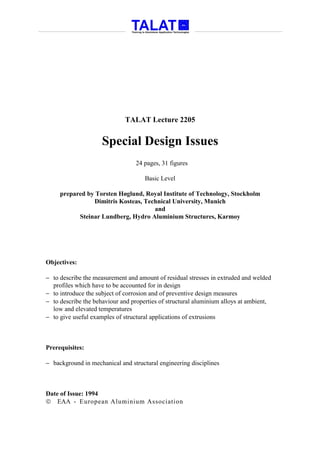
  • 18. 2205.03 Working Temperature • Mechanical properties • Aluminium alloy structures exposed to low temperatures • Aluminium alloy structures exposed to elevated temperatures • Linear expansion Mechanical Properties The strength of aluminium alloys is highest at absolute zero and decreases as the temperature up to the melting point (Figure 2205.03.01). The variation of strength depends on the type of alloy and temper. At low temperatures aluminium alloys have no tendency to brittleness which occurs in many steels. Strength in MPa A5 in % 400 60 300 50 Elongation 200 40 of rupture Ultimate 30 strength 100 Yield strength 20 -200 -100 0 100 200 Temperature in deg. Celsius alu Effect of Temperature on Strength and Training in Aluminium Application Technologies Elongation of 5083 - H112 2205.03.01 The tables in Figure 2205.03.02, Figure 2205.03.04 and Figure 2205.03.04 show in percentage the variation of strength, Young’s modulus of elasticity and the elongation of rupture (A5) between - 200 °C and + 200 °C for some alloys. TALAT 2205 18
  • 19. Aluminium Alloy Structures Exposed to low Temperatures Low temperatures have the effect of improving the mechanical properties and often also the toughness of aluminum alloys without any tendency to brittleness. Alloy and Yield strength in % at various temperatures in ° C temper -200 -100 +25 +100 +200 5052-H34 115 100 100 100 50 5083-H112 120 115 100 95 55 5454-H32 115 105 100 95 70 6061-T6 135 105 100 95 40 6063-T6 115 105 100 95 20 6082-T6 115 105 100 95 40 Source: C. Marsh, Alcan Canada Products Ltd., 1983 alu Yield Strength in % for Some Alloys in the 2205.03.02 Training in Aluminium Application Technologies Temperature Range From -200 to +200 °C Young´s Modulus of Elasticity in % in the temperature range from -200 to +200 °C -200 -100 +25 +100 +200 Elastic Modulus 110 105 100 100 90 Source: C. Marsh, Alcan Canada Products Ltd., 1983 alu Young´s Modulus of Elasticity in % in the Temperature 2205.03.03 Training in Aluminium Application Technologies Range From -200 to +200 °C Elongation of Rupture (A5) in % in the Temperature Range From -200 to +200 °C Alloy and -200 -100 +25 +100 +200 temper 5052-H34 25 19 14 16 45 5083-H112 36 31 25 36 60 5454-H32 30 22 16 18 45 6061-T6 22 18 17 18 28 6063-T6 21 17 18 19 40 6082-T6 22 18 17 19 40 Source: Aluminium Taschenbuch, 14th Ed. Aluminium-Verlag, 1984 alu Elongation of Rupture (A5) in % in the Temperature 2205.03.04 Training in Aluminium Application Technologies Range From -200 to +200 °C The heat affected zone of welded structures will also have an improvement of the mechanical properties, but the elongation of rupture (A5) will usually be the same as at room temperature. TALAT 2205 19
  • 20. Structures in aluminium alloys for low temperature conditions can, therefore, be designed according to the codes and regulations applicable to normal, ambient temperatures. An explanation for the improved mechanical behaviour of aluminium structures at low temperatures is that the difference between the ultimate strength and the yield strength increase when the temperature decreases towards absolute zero. The safety factor against fracture will for that reason increase with decreasing temperature. There is no lower temperature limit for the application of structural aluminium alloys. Aluminium Alloy Structures Exposed to Elevated Temperatures. The strength of aluminium alloys decreases when the metal temperature increases beyond room temperature. Most aluminum alloys suffer from considerable strength reduction at temperatures between 120 - 250 °C. Alloys which are age-hardened or strain-hardened will also loose some of their original strength during a temporary period at elevated temperatures between 100 - 150 °C. Under the prolonged application of a stresses of sufficient magnitude at elevated temperatures, aluminium alloys will creep and may rupture after a period of time. This behaviour does not enter into the design considerations for structures below 100 °C but may require study for high temperature applications. Maximum working temperatures for an aluminium alloy structure can be set to 100 °C. Linear Thermal Expansion. When aluminium alloy structures are connected to structures made of other material and if they are subjected to larger temperature fluctuations, stresses caused by the differences in linear thermal expansion must be taken into consideration. In the temperature range from - 100 °C to 0°C the coefficient of linear thermal expansion can be taken as 21,5 · 10-6 1/°C, in the temperature range 0°C to 100°C 23,5 · 10-6 1/°C can be used as an average. When the relative difference in linear expansion is known, Hooke’s law can be used to find the stress in the structure if the expansion will be within the elastic range. TALAT 2205 20
  • 21. 2205.04 Using Extrusions in Design A great advantage in designing aluminium alloy structures is provided by the possibility of using extruded sections. In Lecture 2202 some information is given about availability, limitations and costs of extrusions. In Lecture 2302 "design of joints" a number of examples illustrate the advantageous way of using extrusions in the design of joints. Structural applications sometimes require large members. If these members cannot be produced from single extrusions, welding together smaller extrusions can be a good sol- ution. The welds can than be located in places where the heat affected zones do not reduce the bearing capacity of the member. Figure 2205.04.01 shows an I-beam made of two identical extrusions, welded together with two buttwelds in the middle of the web. The extrusions are produced ready for welding with the groove and backing already attached in the extrusion process. Large I-Beam Designed With Two Identical Extrusions alu Training in Aluminium Application Technologies Large I-Beam Designed With Two Identical Extrusions 2205.04.01 Another way of making I-beams is shown in Figure 2205.04.02. The flanges are made of extrusions and the web is a plate or an extruded flatbar. In such a way the same flange extrusion can be used to make I-beams of different heights. This beam is welded together with four fillet welds. TALAT 2205 21
  • 22. Large I-Beams Made of Extrusions and Plate alu Training in Aluminium Application Technologies Large I-Beams Made of Extrusions and Plate 2205.04.02 An example from a special case: A member must have bending stiffness horizontal in the upper flange and vertical for the whole member. This is solved by using two extrusions welded together with two buttwelds. Figure 2205.04.03 shows the solution. Hollow Beam Design With High Bending Stiffness alu Training in Aluminium Application Technologies Hollow Beam Design With High Bending Stiffness 2205.04.03 In floor structures the extrusion technique can be used by extruding both the floor plate and the stiffener in one extrusion. The extrusions can be put together in several ways: welding, screwing, adhesive bonding or with snap connections, see Figure 2205.04.04. TALAT 2205 22
  • 23. Floor Extrusions joined together by Welding adhesive Adhesive Bonding Locking Screw screw alu Training in Aluminium Application Technologies Floor Extrusions Joined by Various Methods 2205.04.04 2205.05 References [1] Mazzolani, F.M.: Aluminium Alloy Structures. Pitman Advanced Publishing, Program. 1985. [2] ECCS-TC2: European Recommendations for Aluminium Alloy Structures - Fatigue Design. 1992. [3] SINTEF Korrosjonssenteret: Korrosjonshåndbok for aluminium. STF 34 A87116 (In Norwegian). 1987. [4] Cedric March: Strength of aluminium. Alcan Canada Products Ltd. 1983. [5] Aluminium-Taschenbuch, Aluminium-Zentrale e.V. (Herausgeber), Aluminium- Verlag, Düsseldorf. 1984. 2505.06 List of Figures Figure No. Figure Title (Overhead) 2205.01.01 Example of Residual Stresses in a Welded T-Profile 2205.01.02 Sectioning a Test Beam for Measuring of Residual Stresses 2205.01.03 Residual Stresses in an I-Profile of Different Alloys 2205.01.04 Residual Stresses in I-Profiles for Different Manufacturing Processes 2205.01.05 Typical Residual Stress Distribution for a Welded I-Profile Consisting of Flat Plates. 2205.01.06 Typical Residual Stress Distribution For an I-Profile With Flanges Consisting of Extruded Profiles TALAT 2205 23
  • 24. Figure No. Figure Title (Overhead) 2205.01.07 Example of Approximated Residual Stress Distribution. 2205.01.08 Example of the most Common Way of Determining a Residual Stress Distribution. 2205.01.09 Welded Aluminium Beams for Fatigue Tests. 2205.01.10 Residual Stresses Measured in Fatigue Test Beams 2205.02.01 Methods for a Bolted Connection between Steel and Aluminium Alloy for a Corrosive Environment 2205.02.02 Connections Between Steel and Aluminium in Six Different Environments 2205.02.03 Bad (left) and Recommended Designs (right) for Drainage of Containers 2205.02.04 Bad and Recommended Designs for Drainage of Profiles 2205.02.05 Avoiding Corrosion by Condensation at Cold Spots 2205.02.06 Examples of Good and Bad Solutions with Respect to Crevice Corrosion at Bolted and Welded Connections 2205.02.07 Avoiding Unfavourable Fillet Welds and Fillet Welds with Difficult Accessibility 2205.02.08 Avoiding Crevice Corrosion at Beam 2205.02.09 Galvanic Corrosion Caused by Precipitation of Cu-Ions in an Aluminium Pipe 2205.02.10 Explosion Welded Connections Between Steel and Aluminium Alloy 2205.02.11 Recommendations for Corrosion Prevention on Aluminium/Steel Structures on Ship Decks 2205.02.12 Flange Connection Between Two Dissimilar Metals 2205.02.13 Example of a Bolted Connection Between Steel and Aluminium 2205.03.01 Effect of Temperature on Strength and Elongation of 5083 - H112 2205.03.02 Yield Strength in % for Some Alloys in the Temperature Range from - 200 to +200° C 2205.03.03 Young’s Modulus of Elasticity in % in the Temperature Range from -200 to +200° C 2205.03.04 Elongation of Rupture (A5) in % in the Temperature Range from -200 to +200° C 2205.04.01 Large I-Beam Designed with two Identical Extrusions 2205.04.02 Large I-Beams Made of Extrusions and Plate 2205.04.03 Hollow Beam Design with High Bending Stiffness 2205.04.04 Floor Extrusions Joined by Various Methods TALAT 2205 24