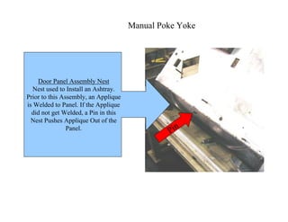
1. Manual Poke Yoke
Pin
Door Panel Assembly Nest
Nest used to Install an Ashtray.
Prior to this Assembly, an Applique
is Welded to Panel. If the Applique
did not get Welded, a Pin in this
Nest Pushes Applique Out of the
Panel.
2. Positive Location
Swing Device
Insulator Sonic Welder
Insulator would not Stay in
Location. This Swing Device
was Added, that Pushes the
Insulator and Holds in
Location when the Nest Raises
to Weld Location.
3. Positive Location
Insulator Sonic Welder
Insulator would not Stay in
Location. This Block Device
was Added, that Holds the
Insulator in Location.
4. Positive Location
Examples of Nest
that are Milled or
Fabricated to Match
the Contour of the
Component Getting
Installed to the Product.
This Ensures Proper
Alignment.
O-Flex Tube Nest
Side Impact Foam Buns
Side Air Bag Bun
5. Operator Visual Aides
Examples of Visual Aides.
Lighted Panels to Show
Operators what Components
are Loaded or Missing in the Fixture.
Also, Lights will Blink if a Component
did not get Installed onto the Product.
6. Operator Interface
Touch Screen Interface Systems
Touch Screens;
•Used to Alarm Operators of Assembly Errors
•Used to Force Operator to Acknowledge Errors,
this Ensures Operator knows there was an
Assembly Error. (Parts are not Released
from Fixture Until Operator
Acknowledges Error)
7. Digital Weighs Scales used to Count
Box Quantities for Bulk Pack Parts.
Ensures Proper Pack Quantities.
Pack Quantities
8. Part Separation
This Fixture Counts and Separates LH and RH Parts.
Operator Loads 8 parts into Nest, and Activates Fixture.
Fixture Shuttles Away from Operator, and Parts Slide into
Packaging below the Fixture. Fixture Counts Number of Parts
in each Box using Fiber Optic Sensors and Lights up when
Box is Full.
Shuttle
LH
RH
9. Part Separation
Clip Fixture Designed to Ensure LH and RH Parts do not get Mixed.
Operator Loads Parts (LH & RH), Activates Fixture, Clips get
Installed. LH Clip Installer Retracts, Operator Packs LH Part, Once
Sensors are Broken Over LH Box, the RH Clip Installer Retracts
Releasing the RH Part. Operator Must Follow Sequence, or Fixture Stops.
LH
RH
Sensors
Sensors
10. Fixture Verification
Fixture Designed with Verification of Process.
The Parts are Marked by the Fixture after Operation.
The Fixture puts a Small Pin Mark on Back of Part.
This Shows that the Part did go through Fixture for Assembly.
If a Part gets Shipped Missing Components, this helps to Verify the Fixture
was or was not Used.
Additionally, Fixture has Part Clamps, that do not Release until Completed Cycle.
Cylinder Marks Part
Part Clamp
11. Assembly Verification
Fixture has a Electric Screw Gun
that Verifies Proper Torque and
Proper Number of Screws
get Installed.
The Part will not Release, unless
Torque and Screw Count is Correct.
Screw Gun
Counter
12. Assembly Verification
This Fixture / Conveyor Checks the Alignment of Previously Assembled Foam Blocks.
This Conveyor is the Last Mechanical Check of a Door Panel Prior to Packaging.
The Operator Places a Fully Assembled Door Panel onto the Conveyor. The Panel
Moves into the Fixture Area and Stops. The Fixture Aligns the Part, and Lowers Frames
that have to Fit Around the Foam Block. If the the Frames Meet Resistance, the Conveyor
Reverses and Sends the Part back to the Operator who Placed the Part onto the Conveyor.
If Okay; the Part Moves to the Packing Operator.
Frames
Conveyor
Part Alignment
Lower
13. Part Clamping
Fixture has Part Clamps, that Lock the
Part into Fixture, until Cycle is
Completed.
Several Methods of Releasing a Part;
•Key Switch Release - Supervisor can
Only Release Part.
•Touch Screen Acknowledgment Button
on Operator Interface.
•Reset Button.
Resetting of a Fixture is a Flag to the
Operator to Check Part for Proper
Assembly.
Part Nest
Clamp
14. Component Verification
Fixture Checks Continuity of a Purchased
Wire Harness.
Fixture will not Operate Unless Wire
Harness is Installed, and Continuity is
Verified.
Wire
15. Component Verification
Pneumatic Assembly Fixture Checks for
Prior Assembled Components. If any
Components are Missing, the Air to the
Assemble Gun does not Activate.
In this Example the Fixture is Checking
for a Metal Ring Stamp to Part. If Ring
is Missing the Pneumatics do not Work.
Prox Sensor
16. Level / Color Verification
Step 1
Step 2
This Assembly is Assembling Parts per
the Assembly Plant Sequence (ILVS).
There are Two Base Colors with Multiple
Colors and Types of Components which
are Assemble to a Door Panel.
Operator Places a Bar Code Label on Back of
Panel, and Places on Scanning Fixture. Fixture
Scans Label and Signals Component Storage
Fixture. A Green Light Turns on Showing the
Operator which Component to Install. The
Operator Removes the Component and Light
Turns Off. If the Wrong Component is Taken,
the Storage Fixture Alarms and Turns on the
Red Light.
LabelScan
Light Off Sensor
17. Level Verification
This Fixture is Verifying the Level of the Part.
This Part has Two Levels, One with a Hole
and One with out.
The Hole is put into the Part Prior to this
Assemble Fixture.
The Fixture Scans the Final Pack Label, and
Checks for the Hole or No Hole. If the Part is
Incorrect, the Fixture Locks Parts in Place and
Alarms the Operator.
Label Scanner
Hole Sensor
18. Process Verification
This Fixture Verifies Part of the Fixture Process
Setup.
Sonic Weld Fixture, that is Welding Plastic to Plastic.
The Fixture had Electrical Transducers Added to the
Electronics and Programming.
The Transducer is Verifying the Electrical Current
going to the Weld Horns is within a Established
Range.
If Electrical Current is above the Range, this is a
Over Weld which is a Complete Burn through of the
Part.
If the Electrical Current is Below the Range, this is
an Incomplete or No Weld Condition.
With Both Cases the Part is Locked in the Fixture,
and the Fixture Alarms and Signals the Operator.
These Transducers are an Inexpensive Solution to
Existing Sonic Welders with out Process Control.
Electrical Trans.
19. Sensor Types
Various Types and Brand Name Sensors.
•Proximity Sensors - Metal and Plastic Detection
•Fiber Optic Sensors
•Laser Sensors - Distance Detecting; Also, Used
when a Sensor can not be put Close to Application
•Limit Switches
•Ring Sensors
•Infrared Sensors
•Water Flow Sensors
Detecting a Clip.
This is an Improvement from a Proximity Sensor.
Typically the Proximity is installed into Clip Driver,
and the Clip would be Detected when Clip is Placed in
the Clip Driver / Tower. The U Shape Eliminates Wear and
Movement of a Standard Proximity Installed in the Clip Tower
Fiber Optic Sensor
Laser Sensor
U Shape Laser Sensor
20. Sensor Types
Detecting a Clip.
Ring Sensor used to Detect if a Clip has been
Previously Installed onto Part. Eliminates Getting
Double Clips Installed onto Product.
Infrared Sensor
Sensor
Ring Sensor Detecting Glue Temperature on Part
Surface Prior to O-Flex Tube getting
Installed. The Glue Temperature
has to be a Certain Temperature
for the Tube to Adhere to Part
21. Sensor Types
Water Flow Sensor
Detecting Water Flow to Mold and Machine.
The Sensor is Tied to Machine Robot. If no
Water Flow the Robot does not Operate.
Probing Sensor
Sensor
Probe Point
Top View
Bottom View
Probe
Probing Poke Yoke
This Device is Probing a Heat Staked Hook on a Door Panel for
Proper Alignment of the Hook.
During the Heat Stake Process the Hook could get out of Alignment.
This Device is a Spring Loaded Ejector Pin that Hits the Probe Point
on the Hook, and Moves up to make a Proximity Sensor.
There is no Other Point on the Hook that would Move the Ejector
Pin to the Proper Height to Make the Sensor
22. Color Verification
Scanner
Color Sensor
Scanner Controller
This Fixture is Assembling Parts per the Assembly Plant Sequence (ILVS).
There are Two Base Colors with Two Versions of the Quarter Panel.
Operator Places a Bar Code Label on Back of Panel, and Places into the
Assembly Fixture. Fixture Scans Label; Verifies Color and Level of Panel. If
Incorrect the Fixture does not Operate.
23. Color Verification
This Fixture is Matching the Color of the Door Panel to the Color of an Armrest.
The Operator Places a Final Pack Label into Scanner Holder, the Fixture Scans
Label and Verifies the Color of the Door Panel to the Color of the Armrest.
If Colors are Incorrect the Fixture will not Allow the Operator to Assemble the
Armrest.
Scanner
Color Sensors
24. Test Parts
These are Examples of Test Parts used to Check Poke Yoke Devices.
For These Examples the Parts are Used to Check a Sonic Welder Electrical
Transducer and to Check for a Missing Molded Tab on the Product.
Testing with these Parts, the Fixture Should Alarm, and Lock Parts into the
Fixture. There are Written Instructions for the Tester to Follow.
Welder Check
Missing Area of
the Weld
M
issing Tab
Part Label for what
Test