Assembly language 8086
•
55 likes•52,249 views

This document provides an introduction to 8086 assembly language programming. It discusses machine code and assembly language, compilers and assemblers, general purpose registers, simple commands, number formats, jumps, labels, logical and shift instructions, and instructions that affect memory. The key points are that assembly language provides a lower-level programming interface than high-level languages, manages memory and registers directly, and uses mnemonics that are assembled into machine code.

Recommended
More Related Content
What's hot
What's hot (20)
Viewers also liked
Viewers also liked (13)
Similar to Assembly language 8086
Similar to Assembly language 8086 (20)
More from John Cutajar
Recently uploaded
Recently uploaded (20)
Assembly language 8086
- 1. 8086 ASSEMBLY LANGUAGE PROGRAMMING Cutajar & Cutajar © 2012
- 2. Machine Code 2 There are occasions when the programmer must program at the machine’s own level. Machine Code programs are tedious to write and highly error prone. 0000111100001111 In situations where a high-level 0010010101010100 language is inappropriate we 1010101010100101 avoid working in machine code most of the time by making the computer do more of the work. Thus we write in assembly language and then the computer converts this assembly language program into machine code.
- 3. Assembly Language 3 In assembly language, a mneumonic (i.e. memory aid) is used as a short notation for the instruction to be used. Assembly Machine Code Language SUB AX,BX 001010111000011 MOV CX,AX 100010111001000 MOV DX,0 10111010000000000000000 Assembly language is an intermediate step between high level languages and machine code. Most features present in HLL are not present in Assembly Language as type checking etc.
- 4. Compilers / Assemblers 4 High-level Languages such as Pascal Program Pascal programs are sometimes Compiler converted firstly to assembly language by a computer program Assembler language Program called compiler and then into machine code by another Assembler program called assembler Machine Code Program This version is actually loaded and executed
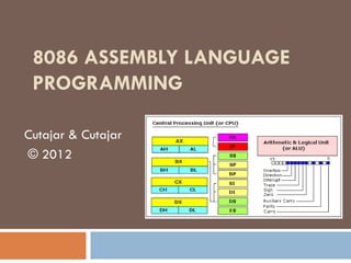
- 5. General Purpose Registers 5 AH AL There are 4 general purpose registers in AX the 8086. BH BL They are all 16-bit registers Each byte can be BX addressed individually CH CL by specifying the High order or the Low order byte of the register. CX DH DL DX
- 6. Some Simple Commands 6 MOV AX,3 ; Put 3 into register AX ADD AX,2 ; Add 2 to the contents of AX MOV BX,AX ; Copy the contents of AX in BX INC CX ; Add 1 to the contents of CX DEC DX ; Subtract 1 from the contents of DX SUB AX,4 ; Subtract 4 from the contents of AX MUL BX ; Multiply the contents of AX with BX leaving ; the answer in DX-AX DIV BX ; Divide the contents of DX-AX by BX leaving ; the quotient in AX and remainder in DX.
- 7. Number Formats 7 AX AH AL MOV AH,01010101B 0 1 0 1 0 1 0 1 MOV AL,00100111B 0 1 0 1 0 1 0 1 0 0 1 0 0 1 1 1 MOV AX,3 0 0 0 0 0 0 0 0 0 0 0 0 0 0 1 1 MOV AH,AL 0 0 0 0 0 0 1 1 0 0 0 0 0 0 1 1 MOV AL,10D 0 0 0 0 0 0 1 1 0 0 0 0 1 0 1 0 MOV AL,10H 0 0 0 0 0 0 1 1 0 0 0 1 0 0 0 0 In case a number is moved (copied) into the register the base of a is specified by a letter B for Binary, D for Decimal and H for Hex.
- 8. AMBIGUITY 8 Consider the instruction MOV DL, AH Does it mean ‘copy the contents of register AH to DL or Does it mean ‘copy A in hexadecimal into register DL To avoid this ambiguity all hexadecimal numbers must start with a number. This can always be done by preceding a number starting with A,B,C,D,E and F with a preceding zero to remove ambiguity. Thus MOV DL, AH means copy AH to DL whilst MOV DL, 0AH means sore hexadecimal A to DL
- 9. The Flags Register 9 Some of the instructions (but not all) affect the flag register. The flag register signals the status of the CPU after the last operation performed. For example if SUB AX,2 results in zero the ZF get 1 (lights on) indicating that the result of the last operation was zero.
- 10. JUMPS 10 Jump instructions allow the 8086 to take decisions according to information provided by the flag register. For example, if AX and BX contain the ASCII code for the same letter then do one thing, if not then do another. ` … CMP AX,BX ; Compares the contents of BX with that of AX JE SAME ; Jump if they are equal to the point ; in the code labeled SAME … ; Obey these instructions if the contents of AX … ; is not equal to that of BX SAME: MOV CX,AX ; Program continues from here if AX = BX. …
- 11. Labels 11 We saw that the jump instruction has a general format JE <label> where <label> is a facility offered by the assembler. These labels are converted by the assembler to exact address where the program is to continue. Labels must start with a letter and can contain thereafter letters, numbers and underscores (_). Spaces and punctuation marks are not permitted Avoid using keywords in labels Once_again, Next, Name34, this_37 are permitted as labels 3rdday, tues+wed and semi;colons are not permitted as labels.
- 12. JUMP Conditions 12 JA/JNBE (CF and ZF) = 0 Above / Not Below or Equal JAE/JNB CF = 0 Above or Equal / Not Below JB/JNAE/JC CF = 1 Below / Not Above or Equal / Carry JBE/JNA (CF or ZF) = 1 Below or Equal / Not Above JE/JZ ZF = 1 Equal / Zero JMP none Unconditionally JNC CF = 0 No Carry JNE/JNZ ZF = 0 Not Equal / Not Zero JNO OF = 0 No Overflow JNP/JPO PF = 0 No Parity / Parity Odd JNS SF = 0 No Sign / Positive JO OF = 1 Overflow JP/JPE PF = 1 Parity / Parity Even JS SF = 1 Sign JG/JNLE ZF = 0 and SF = OF Greater / Not Less nor Equal JGE/JNL SF = OF Grater or Equal / Not Less JL / JNGE SF <> OF Less / Not Greater nor Equal JLE/JNG (ZF = 1) or (SF <> OF) Less or equal / not greater JCXZ Register CX = 0 CX is equal to zero
- 13. Example using Jumps 13 MOV CX, AX ; Keep a copy of AX before modification SUB AX,BX ; AX := AX – BX JZ MAKE1 ; This is instruction will cause execution ; to continue from MAKE1 if AX was ; equal to BX (subtraction resulted in Zero) MOV DX, 0 ; Otherwise store 0 in DX JMP RESET ; Jump to RESTORE where AX is restored ; thus avoiding the next instruction MAKE1: MOV DX, 1 ; If AX = BX then we set DX to 1 RESET: MOV AX, CX ; Restore the old value of AX Note that in the Code a colon ends a label position
- 14. The Logical Family 14 AND NOT (Invert: One’s Complement) Contents of AX = 0000101011100011 Contents of AX = 0000101011100011 Contents of BX = 1001100000100001 Contents of AX = 1111010100011100 Contents of AX = 0000100000100001 after NOT AX is executed after AND AX,BX is executed OR TEST Contents of AX = 0000101011100011 Contents of AX = 0000101011100011 Contents of BX = 1001100000100001 Contents of BX = 1001100000100001 Contents of AX = 1001101011100011 Contents of AX = 0000101011100011 after OR AX,BX is executed after TEST AX,BX is executed XOR Similar to AND but the result is not stored in AX Contents of AX = 0000101011100011 but only the Z-flag is changed Contents of BX = 1001100000100001 NEG (Two’s Complement) Contents of AX = 1001001011000010 Contents of AX = 0000101011100011 after XOR AX,BX is executed Contents of AX = 1111010100011101 after NEG AX is executed
- 15. Use of Logical Family 15 Symbol ASCII (Dec) ASCII (Hex) By Making an AND between an ASCII value and 0FH 0 48 30 we can obtain the required number. 1 49 31 Say we AND 33H = 00110011B 2 50 32 with 0FH = 00001111B 3 51 33 We obtain = 00000011B (3) 4 52 34 5 53 35 By Making an OR between a number value and 30H we 6 54 36 can obtain its ASCII code. 7 55 37 Say we OR 05H = 00000101B 8 56 38 with 30H = 00110101B We obtain = 00110101B 9 57 39 (ASCII value for ‘5’)
- 16. Masking 16 By the use of masking we can set or test individual bits of a register Suppose we want to set the 3rd. bit of AX to 1 leaving the others unchanged. Suppose we want to test the if the AX = 0101010100011001 6th. bit of AX is 1 or 0: 04H = 0000000000000100 AX = 0101010100011001 OR AX,04H = 0101010100011101 20H = 0000000000100000 AND AX,20H = 0000000000000000 Suppose we want to set the 5th. So if the result is 0 then that bit of AX to 0 leaving the particular bit was 0, 1 otherwise others unchanged. AX = 0101010100011001 0FFEFH = 1111111111101111 AND AX,0FFEFH = 0101010100001101
- 17. The Shift Family 17 There are two different sets of shift instructions One set for doubling and halving unsigned binary numbers SHL (Shift Left) – doubles SHR (Shift Right) - halves The other for doubling and halving signed binary numbers SAL (Arithmetic Shift Left) – doubles SAR (Arithmetic Shift Right) – halves 0 SHL/SAL CF MSB MSB 0 CF CF MSB SHR SAR
- 18. Shift Examples 18 Instruction CL Initial Contents Final Contents Decimal Binary Decimal Binary CF SHR AL,1 250 11111010 125 01111101 0 SHR AL,CL 3 250 11111010 31 00011111 0 SHL AL,1 23 00010111 46 00101110 0 SHL BL,CL 2 23 00010111 92 01011100 0 SAL BL,1 +23 00010111 +46 00101110 0 SAL DL,CL 4 +3 00000011 +48 00110000 0 SAR AL,1 -126 10000010 -63 11000001 0 SAR AL,CL 2 -126 10000010 -32 11100000 1
- 19. The Rotate Family 19 The rotate is similar to the shift with the exception that the outgoing bit is not lost but rotated back into the shifted register. An Alternative is to rotate through carry, which includes the carry in the rotation process. ROR ROL MSB LSB CF CF RCR RCL MSB LSB CF CF
- 20. Rotates Examples 20 Instruction CL Initial Contents Final Contents CF Binary Binary CF ROR AL,1 0 11111010 01111101 0 ROR AL,CL 3 1 11111010 01011111 0 ROL AL,1 0 00010111 00101110 0 ROL BL,CL 2 1 00010111 01011100 0 RCL BL,1 0 00010111 00101110 0 RCL DL,CL 4 1 00000011 00111000 0 RCR AL,1 1 10000010 11000001 0 RCR AL,CL 2 0 10000010 00100000 1
- 21. Instructions which affect Memory 21 Computer memory is best thought of numbered pigeon holes (called locations), each capable of storing 8 binary digits (a byte) Data can be retrieved from memory, one or [0000] two bytes at a time: [0001] [0002] MOV AL, [20H] will transfer the [0003] Contents of location 20H to AL. [0004] [0005] MOV BX, [20H] will transfer the contents of [0006] [0007] locations 20H and 21H to BX. [0008] MOV [20H], AL will transfer the contents of [0009] [000A] AL to memory location 20H [000B] Location ADDRESS [000C] Location CONTENTS
- 22. Changing addresses 22 Varying an address whilst a program is running involves specifying the locations concerned in a register. From all the general purpose registers BX is the only capable of storing such addresses. Thus MOV AX, [CX] is illegal Whilst MOV CL, [BX] copies the contents of memory location whose address is specified by BX into the register CL. And MOV [BX], AL copies the contents of AL in the memory location whose address is specified in BX
- 23. Examples Affecting Memory 23 Consider the checkerboard memory test where a section of memory is filled with alternate 01010101 and 10101010. The following program does the checkerboard test on locations 200H-300H inclusive. MOV BX,200H MOV AX,1010101001010101B NEXT: MOV [BX],AX INC BX CMP BX,300H JLE NEXT
- 24. The DS Register 24 The 8086 can address a total of 1 Megabyte. Rather than representing each address as a 20-bit unsigned number, memory is thought of as being divided uo into segments each of which contains 216 locations. In this way an address can be thought of as consisting of two parts: a 16-bit segment address and a 16-bit offset from the start of the segment. Thus , 020A:1BCD denotes offset 1BCDH from the start of segment 020AH.
- 25. Effective Address 25 The actual address is calculated from the Offset segment and offset values as follows: 15 0 Logical Address 1. Add a zero to the right-hand 15 0 side of the segment register. Segment Register 0000 2. Add the offset to this. Example = 020A:1BCD Segment = 020AH -> 020A0H + ADDER Offset = 1BCDH -> 1BCDH Address = 03C6DH 19 0 Thus if DS = 500H the instruction Physical Memory Address MOV AX,[200H] would actually move The contents of location 5200H
- 26. The Instruction Pointer (IP) 26 The computer keeps track of the next line to be executed by keeping its address in a special START . This is the register called the Instruction Pointer (IP) or line which is Program Counter. . . executing This register is relative to CS as segment register and points to the next instruction to MOV AX,BX be executed. MOV CX,05H The contents of this register is updated with MOV DX,AX IP every instruction executed. . Thus a program is executed sequentially line . by line .
- 27. The Stack 27 The Stack is a portion of memory which, like a stack of plates in a canteen, is organized on a Last- In-First-Out basis. Thus the item which was put last on the stack is the first to be withdrawn
- 28. The Stack Pointer 28 [0000] [0002] The Stack pointer keeps track of the [0004] position of the last item placed on the [0006] [0008] stack (i.e. the Top Of Stack) [000A] [000C] SP [000E] [0010] [0012] [0014] The Stack is organized in words, (i.e. two [0016] bytes at a time). Thus the stack pointer is [0018] incremented or decremented by 2. Note that on placing items on the The Stack Pointer points to the last stack the address decreases occupied locations on the stack
- 29. PUSH & POP 29 PUSH AX AX The two set of instructions which [0000] [0002] [0004] explicitly modify the stack are the [0006] [0008] NEW SP PUSH (which places items on the OLD SP [000A] [000C] stack) and the POP (which [000E] [0010] retrieves items from the stack). In [0012] [0014] both cases, the stack pointer is [0016] [0018] adjusted accordingly to point POP AX always to the top of stack. [0000] AX [0002] Thus PUSH AX means SP=SP-2 [0004] [0006] and AX -> [SP] [0008] [000A] OLD SP NEW SP [000C] POP AX means [SP] -> AX and [000E] [0010] SP=SP+2. [0012] [0014] [0016] [0018]
- 30. Subroutines 30 In high-level languages, procedures START SUB1 PROC . make it possible to break a large . . program down into smaller pieces so . . . RET that each piece can be shown to work independently. In this way the final CALL SUB1 program is built up of a number of . trusty bricks and is easier to debug . because the error is either localized to . one subprogram or its interlinking. This has also the advantage of re- usability of bricks.
- 31. The CALL Mechanism 31 Although at first sight the CALL START SUB1 PROC and RET mechanism can be . . . implemented by using two JMP’s. . . In fact this cannot be done since . RET the CALL mechanism remembers CALL SUB1 the place where it was called from 1 . and returns to the line following it. . Thus this is not a fixed address. . CALL SUB1 . 2 . .
- 32. The Return Mechanism 32 When a CALL is encountered the current value of the instruction pointer is pushed on the stack and the it is filled with the address stated by the call. Since the fetch cycle goes to search for the instruction pointed at by the instruction pointer, the program continues it’s execution from the first statement in the subroutine. On encountering the RET instruction the contents of the IP is popped from the stack thus continuing the execution where it was suspended. Thus care must be taken to leave the return address intact before leaving a subroutine. (i.e. a symmetrical number of pushes and pops within the subroutine)
- 33. NEAR and FAR 33 When a procedure lies within the same segment as the calling program (intra-segment) it can be declared as NEAR. Thus the return address can Offset be specified as just an offset thus needing 1 word When the does not lie in the same segment as the calling program (inter-segment) it is declared as FAR. Thus the return address must specify the Offset segment and the offset, thus occupying 2 words. Segment
- 34. Register Parameters 34 The easiest way to pass a parameter to and fro a subprogram is by the use of the general purpose registers. ADDITION PROC NEAR ;Procedure to add two numbers MOV AX,BX ;First parameter in BX ADD AX,CX ;Add second parameter in CX RET ;Return ( result in AX ) ADDITION ENDP ;End of procedure definition … MOV BX,4 ;Assign first parameter MOV CX,7 ;Assign second parameter CALL ADDITION ;Call their addition MOV [RES],AX ;Store the result returned
- 35. Parameters on STACK 35 Passing parameters in registers is very straightforward but limiting SP Return Address For the CALL the number of parameters passed. When several parameters are to Parameters be passed to the subroutine, they are pushed on the stack prior to the subroutine call. Items on the stack prior to CALL
- 36. Retrieving parameters from the Stack 36 Accessing parameters placed on the stack cannot easily be Return Address done using PUSH and POP SP/BP For the CALL since the Stack Pointer must point to the return address. [BP+2] This is done using the Base Pointer (BP) which uses [BP+4] Parameters Stack Segment by default. First the SP is copied in the [BP+6] BP then the parameter is Items on the accessed using an offset from stack prior to BP CALL Ex. MOV AX,[BP+2]
- 37. Local Variables 37 Local variables are pushed [BP-6] on the stack and can be [BP-4] Local accessed using a negative Variables [BP-2] displacement Return Address SP/BP Ex MOV AX, [BP-2] For the CALL retrieves the first local [BP+2] parameter from the stack. [BP+4] Parameters [BP+6] Items on the stack prior to CALL
- 38. Discarding Parameters after CALL 38 The RET command has an option to discard the Return Address OLD SP parameters previously pushed For the CALL on the stack Example: RET 6 Parameters This discards the return address and an additional 6 bytes. Items on the In this manner the SP NEW SP stack prior to returns to the position it CALL occupied before the parameters were pushed.
- 39. Example – Factorial (recursive call) 39 FACT PROC NEAR CMP BX,1 ;Input parameter (n) is in BX JNE RECUR ;If n <> 1 then recurse MOV AX,1 ;else return(1) JMP DONE ; RECUR: PUSH BX ;Store temporarily the value of n DEC BX ; CALL FACT ;Call FACT(n-1) returning value AX POP BX ;Recall n IMUL BX ;FACT:= n*FACT(n-1) DONE: RET FACT ENDP
- 40. Software Interrupts 40 Software interrupts are like hardware interrupts which are generated by the program itself. From the interrupt number, the CPU derives the address of the Interrupt service routine which must be executed. Software interrupts in assembly language can be treated as calls to subroutines of other programs which are currently running on the computer. One of the most famous software interrupt is Interrupt No. 21H, which branches in the operating system, and permits the use of PC-DOS functions defined there. The function required to be performed by DOS is specified in AH prior to the the interrupt. The functions return and accept values in various registers. AN interrupt is called using the instruction INT followed by the interrupt number . For example: INT 21H
- 41. Some INT 21H functions 41 Function Description Explanation Number 1 Keyboard Waits until a character is typed at the keyboard and then puts the ASCII Input code for that character in register AL and echoed to screen (echoed) 2 Display Prints the character whose ASCII code is in DL Output 8 Keyboard Waits until a character is typed at the keyboard and then puts the ASCII Input code for that character in register AL and NOT echoed to screen (No echo) 9 Display Prints a series of characters stored in memory starting with the one in the String address given in DX (relative to DS).Stop when the ASCII code for $ is encountered
- 42. INT 21H Example 42 Prompt DB ‘Please enter 1 or 2: ‘,13D,10D,’$’ Song1 DB ‘So you think you can tell heaven from hell’ Song2 DB ‘Blue Sky is in pain’,13D,10D,’$’ ASK: MOV DX, OFFSET Prompt MOV AH,09H This is only a INT 21H program fragment to illustrate the use of GET: MOV AH,01H interrupt 21H – For INT 21H full details consult the MASM notes CMP AL,01H JE NEXT MOV DX, OFFSET Song1 MOV AH,09H INT 21H
- 43. Number Representation 43 3 7 KEYS One of the disadvantage of reading numbers as a series of ASCII codes for digits is that, before any arithmetic can be performed on such numbers, 33H 37H ASCII their binary equivalents have to be calculated. Thus, if the decimal number 37 was typed at the keyboard, the ASCII codes for 3 and 7 (33H and 3 7 BINARY 37H) would have to be converted to their binary x10 equivalents, and then the binary equivalents, and then the binary equivalent of the first digit 30 multiplied by ten and added to the second. + BCD is a way of representing numbers which avoids the need for conversions of this sort. 37
- 44. Binary Coded Decimal (BCD) 44 BCD Binary BCD is a way of representing numbers which avoids the need of a lot of conversions. 0 0000 The principle used is to encode each decimal digit separately 1 0001 in their unsigned 4-bit equivalents. 2 0010 Since the computer memory is organized in bytes of 8 bits, 3 0011 we can represent BCD digits as: 4 0100 Packed BCD : where two digits are packed in a byte Ex. 5 0101 37 = 0011 0111 6 0110 Unpacked BCD: where each digit is expanded on 8 bits. 7 0111 Ex 37 = 00000011 000001111 8 1000 9 1001
- 45. Arithmetic Operations Binary BCD 45 0000 0 0001 1 0010 2 At first sight we can see that there are 6 unused 0011 3 binary patterns in BCD corresponding to the hex 0100 4 6 letter digits A, B, C, D, E and F. 0101 5 Thus this system is less compact. 0110 6 0111 7 In the arithmetic operations it also involves some 1000 8 complications if the answer contains any of the 1001 9 bit patterns not represented in BCD 1010 Unused Not all is lost however, additional instructions 1011 Unused exist to overcome this problem 1100 Unused 1101 Unused 1110 Unused 1111 Unused
- 46. BCD Addition 46 If the addition doesn’t produce a result which passes 24 0010 0100 + through the forbidden range, no problem arises. 13 0001 0011 If however the result produced contains a forbidden 37 0011 0111 OK digit, it has to be adjusted. 19 0001 1001 + This is done by adding another 6 to the result to 24 0010 0100 overcome the forbidden range. 3? 0011 1101 + NOT OK This adjustment is done automatically using the DAA 06 0000 0110 ADJUST 43 0100 0011 instruction for packed and the AAA instruction for unpacked BCD via the AL register. AUXILIARY CARRY The Auxiliary carry exist in the flag register to indicate 1 a carry from the least significant BCD digit to the 19 0001 1001 + most significant. 18 0001 1000 31 0011 0001
- 47. BCD Subtraction 47 24 0010 0100 - If the subtraction doesn’t produce a result which passes 13 0001 0011 through the forbidden range or no borrow is required no 11 0001 0001 OK problem arises. If however the result produced contains a forbidden digit, it 35 0011 0101 - has to be adjusted. 16 0001 0110 This is done by subtracting another 6 to the result to 1? 0001 1111 - NOT OK overcome the forbidden range. 06 0000 0110 ADJUST This adjustment is done automatically using the DAS 19 0001 1001 instruction for packed and the AAS instruction for unpacked BCD 1 AUXILIARY 21 0010 0001 - The Auxiliary carry here become a borrow and the result 19 0001 1001 must be adjusted whenever this carry is set since the borrow 08 0000 1000 - BORROW is worth 16 not 10. 06 0000 0110 ADJUST 02 0000 0010
- 48. Example 1 : Addition 48 Suppose we have a long packed BCD CX:0003H Length of numbers SI:0400H Number 1 number contained in a number of DI:0500H Number 2 memory locations, the number of BX:0600H Answer these locations is contained in CX and the first number starts at 400H Location Contents and the second at 500H. And the 400H 41 L.S.D. 401H 98 result is to be stored in the locations 402H 01 at 600H. 403H ?? Here we use SI (Source Index) and . 500H 64 L.S.D. DI (Destination Index) registers 501H 71 which are two 16-bit registers which 502H 02 like BX can address the memory. . 600H 05 601H 70 After 602H 04 execution 603H 00
- 49. Example 1: Code 49 CLC ;Clear carry for first digit NEXT: MOV AL,[SI] ;Get digit ADC AL,[DI] ;Add corresponding digit DAA ;Adjust for BCD MOV [BX],AL ;Store answer digit INC SI ;Increment pointers INC DI INC BX DEC CX ;decrement counter JNZ NEXT ;do next digit MOV AL,0 ;adjust last digit ADC AL,0 MOV [BX],AL
- 50. Addition and Subtraction with carry or 50 borrow In assembly language there are two versions of addition and two versions of subtraction. CF CF ADD - Simple addition of two numbers 0 ADC - Adds two numbers together with the carry flag 0 SUB – Simple subtraction of two numbers SBC – Subtracts the second number and Last 0 1 1 the carry flag (borrow) addition in 00 01 98 41 + This provides a means of adding numbers case of an 00 02 71 64 outgoing 00 04 70 05 greater than 32-bits. carry CLC clears the carry for the first digit addition
- 51. Example 1 : Multiplication 51 Suppose we have a long unpacked CX:0004H Length of numbers BCD number contained in a number SI:0400H Multiplicand of memory locations, the number of DL:06H Multiplier these locations is contained in CX DI:0600H Answer and the first number starts at 400H Location Contents and the second is in DL. And the 400H 01 L.S.D. result of their multiplication is to be 401H 09 402H 02 stored in the locations at 600H. 403H 08 . 600H 06 601H 04 After 602H 07 execution 603H 09 604H 04
- 52. Example 2: Procedure 52 Remembering the multiplication algorithm, applied to 8291*6 is: 1. 6 times 1 is 6, we write down 6 and carry 0 2. 6 times 9 is 54, we add the previous carry (0) get 54, we write down 4 and carry 5. 3. 6 times 2 is 12, we add the previous carry (5) get 17, we write down 7 and carry 1. 4. 6 times 8 is 48, we add the previous carry (1) get 49, we write down 9 and carry 4 5. Since it was the last digit to be multiplied we just write down 4 4 1 5 0 8291x6 6 49746
- 53. Example 2: Code 53 MOV AL,00H MOV [DI],AL ;Set “previous carry” to zero NEXT: MOV AL,[SI] ;Get digit of Multiplicand MUL DL ;Multiply by Multiplier AAM ;ASCII adjust digit ADD AL,[DI] ;Add “previous carry” AAA ;ASCII adjust MOV [DI],AL ;Write down Digit INC DI ;point to next digits INC SI MOV [DI],AH ;Store “previous carry” DEC CX ;Check if ready JNZ NEXT
- 54. The Compare Instruction 54 The compare instruction does not change the contents of the registers involved but only sets the flag register accordingly. The actual operation performed by the compare is a subtraction, leaving the source and destination registers intact Consider CMP AX,BX : Flags are set according to the result of subtracting BX from AX: If AX = BX then the ZF is set to 1 If AX > BX then the ZF is set to 0 and CF is set to 0 too If AX < BX then we need an external borrow, which is reflected in CF = 1 These flags are tested in the ABOVE or BELOW jumps which test unsigned numbers The GREATER and LESS jumps are for signed numbers and work on the SF, OF and the ZF instead
- 55. Addressing Modes 55 The addressing modes deal with the source and destination of the data required by the instruction. This can be either a register or a location in memory, or even a port. Various addressing modes exist: Register Addressing Immediate and Direct Addressing Indirect Addressing Indexed Addressing Based Addressing Based-Indexed Addressing Computer Logic II
- 56. Register Addressing 56 This addressing mode General Purpose Segment Registers involves the contents of AX AH AL CS the register directly as BX BH BL DS for example: CX CH CL SS MOV AX, BX DX DH DL ES MOV CL, DL Note that the IP and SI FLAGS Flags register cannot be DI IP accessed directly by the SP programmer BP AX BX Ex. MOV AX,BX
- 57. Immediate and Direct Addressing 57 In Immediate addressing – for example Ex. MOV CL,61H MOV CL,61H – the immediate operand CL 61H 61H is stored as part of the instruction. Thus the number 61H is loaded directly in CL. Direct addressing is similar except that in Ex. MOV AL,[210H] this case the effective address of one of the AL operands is taken directly from the instruction. Thus in MOV AL, [210H] the contents of location 210H relative to DS is put in AL (DS:210H) 75H
- 58. Indirect Addressing 58 With indirect addressing, the Example MOV DL,[BX] effective address is found in either Say BX contains the address 0200H the BX, SI or DI registers. I.e. the relative to DS effective address is not found DL directly in the instruction itself but indirectly by accessing a register, as in: MOV DL, [BX] (DS:200H) 69H BX Note that this method is useful to pass parameters to subroutines by reference instead of by value.
- 59. Indexed Addressing 59 With indexed addressing, the effective address is calculated by the addition of an index register + Ex. MOV AL,ACCOUNT[SI] Assume that ACCOUNT has displacement. an offset of 0200H relative to For this purpose two index registers exist SI DS and SI contains 05H (source index) and DI (destination index) By default SI and DI relative to DS if not ACCOUNT (DS:200H) for string handling, in which case SI is AL 201H relative to DS and DI is relative to ES. Example MOV AL, ACCOUNT[SI] This adds 202H the address of account to SI to obtain the 203H effective address where data is to be retrieved 204H from. 205H 75H An alternative notation is MOV AL,[SI+BALANCE]
- 60. BASED ADDRESSING 60 Ex. MOV AL,[BX+05H] In based addressing BX or BP are Assume that BX contains used as a variable base of the 0200H address from where the data is to be retrieved or stored. An offset (DS:200H) BX can be added to this base address AL 201H Addresses given in BX are taken 202H relative to DS whereas those in 203H BP are taken relative to SS. 204H Example MOV AL, [BX+05H] 205H 75H
- 61. Based-Indexed Addressing 61 Based-Indexed addressing is a combination Ex. MOV AL,[BX+SI+02H] of the previous two addressing modes. Assume that BX contains The effective address is calculated by 0200H and SI contains 3 summing up the contents of the base register together with the contents of the index register and the given displacement. (DS:200H) BX Example: MOV AL, [BX+SI+2] AL 201H SI 202H Note that although in these examples the MOV 203H instruction is always considered, this can apply 204H to several instructions and the address 02H calculation can apply both to the source and 205H 75H destination of data.
- 62. Default Segment Register 62 Note that the default segment register can be changed using the segment override, i.e. stating the whole General Purpose address in the form DS: Offset AX AH AL BX BH BL Relative to DS by default CX CH CL DX DH DL NORMALLY FOR STRINGS SI Relative to DS by default DS DI Relative to DS by default ES SP Relative to SS by default BP Relative to SS by default IP Relative to CS by default
- 63. Some other useful Instructions 63 CLC: Clear Carry Flag (CF = 0) STC: Set Carry Flag (CF = 1) CMC : Complement Carry Flag (CF = CF) CBW: Convert Byte to Word CWD: Convert Word to Double-Word NEG: Negate (2’s Complement) NOT: Compliment (1’s Complement)
- 64. Reference Books 64 Programming the 8086/86 for the IBM PC and Compatibles . Michael Thorne Microprocessors and Interfacing – Programming and Hardware – Douglas V.Hall Microsoft Macro Assembler – for the MS-DOS Operating Systems – Reference Manual