Journal American Lab Automation 2011 v16 p335
•
1 like•252 views

On-column solvent exchange for purified preparative fractions

Recommended
Recommended
More Related Content
What's hot
What's hot (20)
Viewers also liked
Viewers also liked (16)
Similar to Journal American Lab Automation 2011 v16 p335
Similar to Journal American Lab Automation 2011 v16 p335 (20)
Recently uploaded
Recently uploaded (20)
Journal American Lab Automation 2011 v16 p335
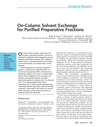
- 1. On-Column Solvent Exchange for Purified Preparative Fractions Gilles H. Goetz,1* Emily Beck,2 and Peter W. Tidswell1 1Pfizer Global Research and Development, Analytical Chemistry and Sample Logistics, St Louis Laboratories, Chesterfield, MO 2School of Medicine, Washington University, St Louis, MO On-column solvent exchange, using many of the principles of solid-phase extraction, has been im-plemented to significantly reduce evaporation cycle time following reverse-phase preparative HPLC. Additional benefits, such as a reduced potential for salt formation, thermal decomposition, and residual solvent, are also described. Fractions obtained from preparative separations, typically in a large volume of acetonitrile:water, are injected into the preparative HPLC and then eluted in acetonitrile, creating a new fraction in a volatile organic solvent. Minimal modification to the instrument was required, and unattended operation is possible. Acetonitrile evaporation is achieved within 3 h, compared with 17 h for aqueous-based fractions; lower temperatures can be used during the evaporation step; mobile-phase additives, likely to form salts with the target compound if concentrated in the fraction, are removed before evaporation; sample recovery and purity are unaffected. (JALA 2011;16:335–46) INTRODUCTION Preparative reversed-phase chromatography has become the purification method of choice in the pharmaceutical industry for small-molecule early-discovery research. Centralized purification groups relying heavily on automation are often responsible for bridging the gap between medicinal chemists and biologists. Along with customized separation conditions, the use of mass-directed fractionation enables the isolation of the target compound from the crude mixture effectively and efficiently. Focus-ing on cost- and time-reduction, these centralized automated platforms provide a high-quality and high-throughput purification platform (Fig. 1). Within this environment, post-purification workup of the collected fractions (including evapo-ration, weighing, reconstitution, and reformatting procedures) can be time-consuming activities but must be performed accurately to ensure that the final product is of high quality. In our laboratories, the fi-nal product is formulated as a stock solution at a standard, known concentration with supporting purity and identity data. It is then sent for immedi-ate testing by project teams, and any remaining ma-terial is held for longer-term storage. Of the various postpurification procedures, evap-oration to dryness of aqueous/organic matrices is the most time consuming and represents the bottle-neck of the whole purification operation (within our laboratories). During this procedure, the col-lected target material must be recovered intact from a solution containing low-volatility solvents (partic-ularly water). Precautions against sample decompo-sition, salt formation, and residual solvent must be taken, because any errors in this step will affect the purity and/or concentration of the final product.1 Previous reports, mirroring our experiences, have shown that the chromatography-enhancing additives Keywords: fraction concentration, solvent exchange, solid-phase extraction, preparative chromatography *Correspondence: Gilles H. Goetz, Ph.D., Pfizer Global Research and Development, Groton laboratories, Eastern Point Road, MS 8118W-305, Groton, CT 06340, USA; Phone: þ1.860.715.6311; Fax: þ1.860.715.3345; E-mail: gilles.h.goetz@pfizer.com 2211-0682/$36.00 Copyright c 2011 by the Society for Laboratory Automation and Screening doi:10.1016/j.jala.2010.02.004 Original Report JALA October 2011 335
- 2. Original Report routinely used during preparative liquid chromatography (LC) separations (formic acid, trifluoroacetic acid (TFA), ammonium hydroxide, and others) get concentrated in the fractions during the evaporation process, potentially leading to salt forms of the target base2 (or, less commonly, acid), to hydrolysis of some functional groups (e.g., esters) or deriva-tization of others (e.g., formylation of amines). The evaporation procedure used in our laboratories is an incompressible overnight run using reduced-pressure and elevated-temperature programs in Genevac HT24 evapora-tors (Genevac, Gardiner, NY). These programs have been shown to isolate the target material consistently as a dry solid from the solvent matrix (water, organic solvent, and volatile additive). These programs cannot, however, prevent the for-mation of salts and, in rare cases, the degradation of the final product. To reduce the time taken for solvent evaporation, avoid salt formation, and reduce exposure to heat (while still ensur-ing that no residual solvent remains), an investigation into the removal of water (and HPLC additives) from the frac-tions before the evaporation step was initiated. Various crite-ria were defined, not least that the quality of the final product must be maintained or improved, little or no capital invest-ment would be required, the existing capabilities of instru-ments would be maintained, and the overall integrity of the purification platform would not be compromised. Other authors have recently described solid-phase extrac-tion (SPE) approaches for handling reverse-phase prepara-tive HPLC fractions.3e5 In this study, the Waters (Milford, MA) on-column SPE concept5 is adapted and customized, and the term on-column solvent exchange is used to describe the procedure of loading fractions back onto the preparative HPLC column under aqueous conditions before eluting them with acetonitrile to yield a water- and additive-free fraction. EXPERIMENTAL Instrumentation Instrument for Initial Analysis of Crude Compounds. Two identical systems consisting of four Waters 1525 micro binary gradient pumps, Waters 2777 sample manager, Waters 2488 dual-wavelength absorbance detector, Waters MUX inter-face and system controller, Waters ZQ mass spectrometer, and four Polymer Labs (Shropshire, UK) PL-ELS2100 evap-orative light scattering detectors were used. Preparative Purification Instrument. Waters 2525 binary gra-dient pump, three Waters 515 HPLC pumps (for at-column-dilution, modifier and MS make-up solvent delivery), Waters pump control module, Waters 2767 sample manager (injec-tionecollection), Waters 2757 sample manager (collection), two Waters 2487 dual-wavelength absorbance detectors, ZQ mass spectrometer, Waters column selector, Waters selector valve (for switching injection mode), two Waters sol-vent selection valves (for additive selection and at-column-dilution Genevac Previous Process Dry Powder 17 h 25 min C 18 Column 8 min 17 h DMSO Water/MeCN At Column Solvent Exchange Process Dry C 18 Column C 18 Column 8 min 5 min Genevac 3 h DMSO Water/MeCN MeCN Powder 3 h 13 min Figure 1. At column solvent exchange process improvements. push solvent selection), and Waters flow splitter (1000:1) made up the preparative instrument. The instrument was controlled using MassLynx, version 4.1 SCN627 (Wa-ters, Milford, MA). Software and Controls. Control of the preparative HPLC components was accomplished through MassLynx, version 4.1 SCN627, operating with the FractionLynx application manager (Waters, Milford, MA). MassLynx controls the pumps, detectors, and the injection arm of the sample man-ager, and FractionLynx controls the fraction collection part of the sample manager. The MassLynx sample list provided all the relevant information for the system to perform an in-jection, such as method, sample location, and injection vol-ume. Additional columns were added to the sample list to indicate the specific target mass or masses for the fraction collection software to monitor. Once the sample was injected and the appropriate masses entered into the sample list, the collection software monitored for the target mass. When the target mass was identified, the collection software di-verted the solvent flow through the fraction collector diverter valve to the waiting fraction tube. The collection software that operates the system does not differentiate between a standard collection routine and this trap and elute routine. The instruments in the system were controlled through the standard MassLynx software through General Purpose In-terface Bus (GPIB), Institute of Electrical and Electronics Engineers, New York (IEEE), Ethernet, and serial port com-munication. The ultraviolet (UV) detectors operated under IEEE, the primary pump and mass spectrometer were under Ethernet control, and the sample managers were controlled through serial ports. The three 515 pumps, the selector valve, the solvent modifier selection valve, and the column selector were all controlled by contact closures from the primary pump, and the watereacetonitrile solvent selection valve was operated off-line manually. Evaporation Systems. Two identical HT24 evaporators were used for the routine removal of solvents from HPLC fractions. 336 JALA October 2011
- 3. Reagents and Materials Mallinckrodt Baker (Philipsburg, NJ) acetonitrile 20 and 4 L, HPLC grade; and EMD Chemicals (Gibbstown, NJ) wa-ter 20 and 4 L, HPLC grade, were used. SigmaeAldrich (St. Louis, MO) ammonium hydroxide American Chemical Soci-ety (ACS) grade reagent and trifluoroacetic acid (TFA) and Mallinckrodt Baker formic acid 88% ACS reagent were used. Waters X-Bridge C18 2.1 50-mm, 5-mm column; Waters SunFire C18 2.1 50-mm, 5-mm column; Waters X-Bridge Prep C18 optimum bed density (OBD) 19 50-mm, 5-mm column; Waters X-Bridge Prep C18 OBD 19 10-mm, 5- mm precolumn; Waters SunFire Prep C18 OBD 19 50- mm, 5-mm column; Waters SunFire Prep C18 OBD 19 10-mm, 5-mm precolumn; Waters X-Bridge Prep C18 OBD 30 100-mm, 5-mm column; Phenomenex (Torrance, CA) AXIA Gemini C18 110A 21.2 50-mm, 5-mm column; Phenomenex AXIA Gemini C18 110A 21.2 10-mm, 5-mm precolumn; and Waters experimental hydrophilic-lipophilic-balanced (HLB) 19 50-mm, 30-mm column, were used. Hardware Configuration Preinjector Fluidic Pathway. Two modifications to the in-strument were performed; the first was the introduction of a solvent selection valve for the at-column-dilution pump to allow the sample to be loaded onto the column with either acetonitrile (in preparative mode) or water (in the solvent-exchange mode). In both modes, this pump delivers 20% of the total flow through the instrument when the at-column- dilution injection protocol is used. The second modification inserted a six-port switching valve ahead of the in-line T used for at-column-dilution injections. This valve is connected to the column, the sample loop, the 2525 pump, and the at-column-dilution pump; it is controlled by MassLynx through contact closures configured in the inlet editor and allows for automated switching between the prepar-ative and solvent-exchange modes (Fig. 2). Autosampler Valve and Syringe Mechanism. A second sam-ple loop (20 mL), to inject the fractions during the solvent-exchange procedure, was installed alongside the original loop (2 mL) for preparative separations. Both loops can be filled with the required accuracy and speed using a 10-mL syringe. To maintain autosampler accuracy, the syringe speed is set to aspirate and dispense at 10% maximum motor power (speed). Autosampler Transfer Tubing. The transfer line volume be-tween the syringe and the needle on the autosampler (also known as the holding loop) was increased from 1.5 to 15 mL to accommodate the larger volumes of sample being aspirated in the on-column solvent-exchange mode. Collection Delay Timing To minimize the volume of water collected during the solvent-exchange procedure, a suitable delay time (from Injector Sample Loop Original Report 1ml/min detection of the compound in the MS to fraction head acti-vation) was found to be 15 s. Methods Initial Analysis of Crude Research Compounds. Aliquots (10 mL; 0.1% of the submitted volume) of the crude compounds were diluted with DMSO (140 mL) to create analytical samples with a concentration typically between 1 and 2 mg/mL. For acidic LC conditions, formic acid (0.1% v/v) was added to both the aqueous and acetonitrile mobile-phase res-ervoirs, and the SunFire C18 2.1 50-mm, 5-mm column was installed on the instrument. For basic conditions, ammonium hydroxide (100 mM) was added to both the aqueous and acetonitrile mobile-phase reservoirs, and the X-Bridge C18 2.1 50-mm, 5-mm column was installed on the instrument. Under both conditions, an isocratic hold at aqueous:or-ganic (95:5) for 1 min was followed by a linear gradient to aqueous:organic (5:95) during 6.75 min and an isocratic hold at the final set point for 1 min. The instrument was then re-turned to the initial conditions and equilibrated for 1 min. The chromatographic run time was 10 min, and the overall duty cycle was 10.5 min because of the ‘‘inject ahead’’ feature of the autosampler. The method’s flow rate was 1 mL/min; the injection volume was 10 mL; UV detection performed at 214 nm, and the Evaporative Light Scattering Detector (ELSD) nebulizer temperature at 40 C. Preparative Separation of Flavone. A known accurate weight of flavone (approximately 1 g) was dissolved in DMSO and then diluted to create a stock solution, typically at either the 30- or the 50-mg/mL level. Aliquots (1.2 mL) were trans-ferred to the matrix tubes with prepierced septa, and 1 mL was injected into the instrument. Main Gradient Pump H2O and MeCN Load Modifier Column Make Up Splitter Waste MS UV UV Primary Fraction Lynx Collection Valve Valve MeCN H2O 26.5 ml/min 2.5ml/min Secondary Fraction Lynx Collection 1ml/min Figure 2. Schematic of the modified Waters FractionLynx Instru-ment configured to perform both preparative separations and on-column solvent exchange using direct-injection and at-column- dilution (with acetonitrile or water) injection protocols. JALA October 2011 337
- 4. Original Report For acidic LC conditions, the modifier pump delivered 3% aqueous formic acid at 1 mL/min ahead of a SunFire Prep C18 OBD 19 50-mm, 5-mm column, equipped with a guard column (30 10 mm, 5 mm). For basic conditions, the modifier pump delivered 3% aqueous ammonium hy-droxide at 1 mL/min ahead of an X-Bridge Prep C18 OBD 30 100-mm, 5-mm column, equipped with a guard column (30 10 mm, 5 mm). Under both conditions, the at-column-dilution solvent se-lector valve was used to select the acetonitrile reservoir (Fig. 3A). The at-column-dilution pump continuously deliv-ered acetonitrile (2.5 mL/min) through the injection valve; the modifier pump continuously delivered an aqueous solu-tion of the additive (1 mL/min), and the 1525 main pump delivered a binary gradient (26.5 mL/min) for a total flow of 30 mL/min. An isocratic hold at aqueous:organic (85:15) for 1 min was followed by a linear gradient to aqueous:organic (35:65) during 5.75 min, a column wash in acetonitrile for 1 min, and then a return to the initial condi-tions. Column equilibration occurred during the subsequent aspirate/dispense cycle(s). The run time was 8 min, and the overall duty cycle was 10 min. Fractions were collected in tared 18 100-mm glass tubes, evaporated in an evaporator (see later for conditions), the gross weight was measured, and the net weight was calcu-lated. All fraction tube weights were recorded on the same customized Tecan EVO workstation (Tecan Group, Ma¨nne-dorf, Switzerland). Preparative Separation of Caffeine. A known accurate weight of caffeine (1 g) was dissolved in acetonitrile:water (1:1) and then diluted to create a stock solution, typically at either the 30- or the 50-mg/mL level. Aliquots (1.2 mL) were trans-ferred to matrix tubes with prepierced septa, and 1 mL was injected into the instrument. Conditions and practices identical to those used for the separation of flavone were used, except for the gradient pro-file. An isocratic hold at aqueous:organic (100:0) for 1 min was followed by a linear gradient to aqueous:organic (80:20) during 5.75 min, a column wash in acetonitrile for 1 min, and then a return to the initial conditions. Column equilibration occurred during the subsequent aspirate/dis-pense cycle(s). The run time was 8 min, and the overall duty cycle was 10 min. On-Column Solvent Exchange Using Direct Injection. A known accurate weight of either flavone or caffeine (approx-imately 1 g) was dissolved in acetonitrile:water (1:1) to create a stock solution, typically at either the 50- or the 70-mg/mL level. Aliquots (variable volume) were transferred to 18 100-mm fraction tubes and then diluted to the desired concentration with acetonitrile:water (1:1; unless otherwise stated) for a final volume of 10e15 mL. These samples were injected into the instrument. Research samples, as fractions (from preparative experiments; up to 18 mL of total volume), were separately injected into the in-strument. For each injection cycle, samples were aspirated in aliquots (10 mL) and dispensed into the injection port; mul-tiple aspirate/dispense cycles before injection valve switching were required for volumes greater than 10 mL. The 1525 main pump continuously delivered water (30 mL/min) through the injection valve ahead of either an X-Bridge Prep C18 OBD 30 100-mm, 5-mm column, equip-ped with a guard column (30 10 mm, 5 mm) a Gemini C18 110A 21.2 50-mm, 5-mm column, equipped with a guard column (21.2 10 mm, 5 mm) or a Waters experimental HLB (19 50 mm, 30 mm) column. The at-column-dilution and modifier pumps were turned off. An isocratic hold in water for 2 min was followed by an isocratic hold in acetonitrile for 3 min and then a return to the initial conditions. Column equilibration occurred during the subsequent aspirate/dispense cycle(s). For a typical frac-tion volume of 15 mL, the overall run time was 5 min, and A Column Main Gradient Pump B Acetonitrile Water At-Column Dilution Pump ON Sample Loop Main Gradient Pump Column Acetonitrile Water At-Column Dilution Pump ON Sample Loop Figure 3. (A) Pumping configuration in preparative mode using at-column-dilution injection protocol. (B) Configuration in on-column solvent-exchange mode using at-column-dilution injection protocol. 338 JALA October 2011
- 5. the overall duty cycle was 9.5 min. Post-purification practices identical to those described earlier measured the final frac-tion weight gravimetrically. On-Column Solvent Exchange Using At-Column Dilution. Flavone, caffeine, and research samples were prepared and dispensed into the sample loop as described earlier. The same columns were also installed on the instrument. The at-column-dilution solvent selector valve was manu-ally switched over to the water reservoir (Fig. 3B). Initially, the at-column-dilution pump delivered water (6 mL/min) through the injection valve, the 1525 main pump delivered water (24 mL/min) directly to the head of the column, and the modifier pump was turned off. These conditions are maintained during the injection cycle (6 min). The at-column- dilution pump was then turned off, and the 1525 main pump delivered water for two more minutes followed by acetonitrile (30 mL/min) for 3 min to elute the fraction. For a typical fraction volume of 15 mL, the overall run time was 11 min, and the overall duty cycle was 13 min. Postpur-ification practices identical to those described earlier mea-sured the final fraction weight gravimetrically. Evaporation A new short Genevac HT24 program to support the solvent-exchange process consists of two parts. In the first part, rapid ramping from ambient conditions to 250 mbar at 40 C, then slower ramping to 50 mbar over 15 min, before rapid ramping to 11 mbar for 45 min, occurs; the second part is a full vacuum stage lasting 2 h at 40 C. The total cycle lasts for approximately 3 h. RESULTS AND DISCUSSION Effects of Changing the Fluidic Pathway This study was undertaken while attempting to keep an existing preparative HPLC instrument as close to its opti-mized configuration as possible. All modifications performed needed to have a low impact on the existing purification plat-form. For example, modifications could only minimally reduce sample recovery (O90%) and cycle time (!2.5 days). No reduction in final product purity (O80% by UV detec-tion, O85% by ELSD detection, and a 1H NMR spectrum consistent with these purity results) or increase in manual in-tervention could be tolerated. Additionally, the instrument had to remain compatible with the existing infrastructure and work streams. At the beginning of this study, the instrument was config-ured to deliver an aqueous/organic gradient from the master pump (2525 pump), with additives being introduced after mixing by a 515 pump and the sample being injected from a 2767 sample manager using a 515 pump and an at-column- dilution protocol (with acetonitrile as the push sol-vent). Postcolumn UV detection preceded a 1000:1 flow split, with most of the flow being returned to the 2767 sample man-ager for collection, and the remainder of the flow being Original Report diluted with acetonitrile:water:formic acid (60:40:0.1) and en-tering the ZQ mass spectrometer. The MS triggered the 2767 fraction collector. When this primary fraction collector was not active, material entered the waste stream, where the sec-ond UV detector (2487 dual-wavelength absorbance detec-tor) triggered the second fraction collector (2757 sample manager) when a UV response was detected. This secondary collection method ensures that any failure of the MS trigger-ing components does not result in sample loss. It has been in use successfully in our laboratories for more than 2 years and is similar to the approach described by FitzGibbons et al.6 The six-port switching valve was installed to enable the in-strument to be automatically switched from the direct-injection mode (using the 2525 pump to flush the injection loop) to the at-column-dilution injection mode. The first position of six-port switching valve installed dur-ing this study supports the at-column-dilution injection pro-tocol. 7 In this mode, the 515 pump delivers a push solvent through the injection loop, and the 2525 pump delivers the initial conditions to the head of the column. In this way, the sample is flushed from the injection loop with solvent and diluted with the flow from the 2525 pump immediately before entering the column. For preparative separations, the organic modifier (e.g., acetonitrile) is typically used as the push solvent (Fig. 3A). This valve setting can also be used in the solvent-exchange mode for polar compounds, because a fivefold dilution with water is needed to ensure retention on the column (Fig. 3B; this is described in more detail later). The second position of six-port switching valve supports di-rect injection of the sample. In this mode, the 2525 pump de-livers the initial conditions through the injection loop to the head of the columnwhen loading the sample (Fig. 4). Thismode is not normally used for injection of crude samples for prepara-tive separation in our laboratories, but was implemented for use with the on-column solvent-exchange procedure. The installation of the valve allows the instrument to be switched between the preparative mode and solvent- Main Gradient Pump Column Acetonitrile Water At-Column Dilution Pump OFF Sample Loop Figure 4. Configuration in on-column solvent-exchange mode using direct-injection protocol. JALA October 2011 339
- 6. Original Report exchange mode without operator intervention, using a con-tact closure within MassLynx methods. The instrument can, therefore, run both preparative separations and the sub-sequent solvent-exchange procedures unattended. The addition of the solvent selection valve enables the at-column- dilution pump to readily switch between acetonitrile, for at-column-dilution injection of the crude compound for preparative separation, and water, for at-column-dilution of the purified compound in the on-column solvent-exchange mode. This valve was installed on the low-pressure side of the pump head and had no appreciable effect on the performance of the injection protocols, chromatographic separation, or overall instrument performance. Insertion of the 15-mL transfer line on the autosampler was required to support the larger volumes of sample being aspirated and dispensed in the on-column solvent-exchange mode. The effects on both carryover between modes of oper-ation and injections as well as sample recovery were not mea-sured specifically; however, they were measured as part of the overall instrument performance and are described in the fol-lowing sections. Sample Recovery Measurements One of the most important criteria defined during this study was to ensure that high sample recoveries of the final product were maintained. Two separate potential losses of material can occur when the on-column solvent-exchange procedure is in-cluded in the overall purification workflowdduring the pre-parative separation and the solvent-exchange procedure. Sample recovery from both modes of operation was assessed to derive an overall recovery measurement. Sample Recovery During Preparative Liquid Chromatography. Instrument recovery is routinely verified for all preparative instruments in our laboratories using a gravimetric assay of flavone. Figure 5 shows the measured sample recoveries from two instruments; one instrument (triangles) was modi-fied to perform on-column solvent exchange during June 2008, and the second instrument was not modified. This study was completed in October 2008, and both instruments were subsequently used to support the purification platform. The sample recovery measured from both instruments is consistently greater than 85% and typically at or above 90%. Although it could be argued that the unmodified in-strument recovers more material, the differences are small and have little effect on the success of the purification platform. Autosampler Syringe Volume Selection. The 2767 autosam-pler supports two fluidic pathways with a single syringe and drive mechanism. The purification platform in our labo-ratories has been optimized for the injection of mixtures sub-mitted in 1 mL of solvent (normally DMSO); hence, it is critical that the entire sample is injected on to the column to maximize sample recovery. Therefore, the 2-mL injection Figure 5. Measured recoveries of flavone from an instrument modified to perform on-column solvent exchange (triangles) and an unmodified instrument (squares). loop currently installed on the autosampler was retained in one of the flow paths. Based on the maximum volume col-lected in a single fraction tube (18 mL), a 20-mL injection loop was selected for the second flow path to support on-column solvent exchange. With such a large volume difference between the two flow paths, the control of two different syringes to fill the loops is preferred. Unfortunately, this configuration is not supported within the instrument-control software; hence, a single syringe capable of accurately filling both loops had to be selected. Measuring the gravimetric recovery of flavone (30 mg in DMSO; 1 mL) during the preparative separation, 25- and 10-mL syringes were compared with the original 1-mL syringe. Figure 6 shows that nearly-identical sample recov-eries were observed with the 10- and 1-mL syringes, whereas sample recovery was much lower when the 25-mL syringe was used, because the speed of the syringe aspirate and dis-pense steps could not be adequately controlleddsee the fol-lowing. Because one criterion for the acceptable performance of on-column solvent exchange was to maintain purification recovery levels, we sacrificed loading speed (faster using the 25-mL syringe) for sample recovery (higher when using the 10-mL syringe). This compromise requires any fraction con-taining a volume greater than 10 mL to be loaded using two aspirate and dispense cycles before the valve switching. Effects of Altering the Autosampler Syringe Drive Mechanism. The 2767 sample handlers enable customization of the sy-ringe plunger speed as a percentage of full motor power. When aspirating fractions at full speed, during the solvent-exchange procedure, a partial vacuum was created inside the syringe, because the liquid could not travel through the holding loop fast enough. This resulted in a large portion of the sample remaining in the fraction tube. Similarly, when dispensing into the loop at full speed, the sample leaked from the injection port. Combined, these sample losses signifi-cantly reduced sample recovery. 340 JALA October 2011
- 7. Visual inspection of the sample still present in the fraction tube after completion of the injection cycle demonstrated that a syringe motor speed greater than 30% could not be used. To further refine this parameter, recovery of flavone (50 mg in acetonitrile:water [1:1] 15 mL) was measured at motor speeds of 10% and 30% after the sample been eluted from the column in the solvent-exchange mode (Fig. 7). Sample recovery was closely correlated to both the aspira-tion and dispensing speeds, with slower motor speeds leading to higher sample recoveries. However, this slower motor speed increased the length of the overall injection cycle from 6 to 7 min. For our application, this increase in cycle time was an acceptable compromise to ensure that high sample recoveries were obtained, and the motor speed selected was the 10% level. Overall, installing a 10-mL syringe and using aspirate and dispense speeds at 10% of the maximum motor power Original Report ensured that more than 90% of the sample was recovered af-ter both the preparative and on-column solvent-exchange procedures were completed. Effects of Using Multiple Aspirate and Dispense Cycles. The utility of multiple aspirate and dispense cycles, required be-cause the autosampler syringe volume (10 mL) selected was approximately half the size of the injection loop (20 mL), was investigated. This injection protocol did not have any impact on sample recovery when loading the contents of a single fraction tube (Fig. 7); hence, sample recovery was measured after loading from separate fraction tubes. Three separate flavone samples (15 mg in acetonitrile:water [1:1] 15 mL) were loaded into the loop, then injected onto the col-umn as a single injection using the direct-injection protocol, and eluted into a single tube using acetonitrile. 43.2 mg of fla-vone was recovered, representing a 97% sample recovery. This high level of sample recovery permits the on-column sol-vent- exchange mode to be used to pool different fractions if desired. Retention Behavior of Compounds on Column. Previous reports3e5 have used a fivefold aqueous dilution of fractions before or during the injection protocol to ensure that com-pounds are retained by the C18 column and do not break through with the solvent front. The results from this laboratory showed that, for the over-whelming majority of compounds purified, no aqueous dilu-tion of the sample was required, and the sample could be retained on column using a direct-injection protocol. Only three compounds from a set of 130 samples, representing 11 different research projects and 30 chemotypes, were not retained and ‘‘broke through’’ to the solvent front partially or completely when using the direct-injection protocol to load, and these three samples could be successfully loaded (with no breakthrough) using the at-column-dilution protocol. These three compounds were the most polar compounds in the test collection and to mimic this breakthrough behav-ior we selected caffeine, a highly polar and water-soluble compound, to act as a model compound. By developing a method that would retain caffeine, the retention of polar research compounds from our laboratories would be possible. Samples of caffeine were prepared in various acetonitrile: water ratios and then loaded onto the column using either the direct-injection protocol or the at-column-dilution proto-col (with water acting as the push solvent). Figure 8 shows that the C18 column did not retain caffeine using either injec-tion protocol when the acetonitrile content was greater than 40% and that caffeine was fully retained by both injection protocols when the acetonitrile content was 10% or less. When the acetonitrile content was between 10% and 40%, caffeine was completely retained only using the at-column-dilution injection protocol; hence, this injection protocol should be used for the loading of polar compounds. Figure 6. Recovery of flavone (30 mg in DMSO; 1 mL) from a preparative separation using different syringe volumes to perform the injection. Each bar represents an average of three replicate injections. Figure 7. Recovery of flavone (50 mg in acetonitrile:water [1:1] 15 mL) in the on-column solvent-exchange mode, using a 10-mL syringe with different aspirate and dispense speeds. Each bar rep-resents an average of four replicate injections. JALA October 2011 341
- 8. Original Report During this study, the duty cycle of each injection proto-col was monitored, and the at-column dilution protocol was found to be approximately three times longer than the direct-injection protocol. The reason for this is that, to achieve a fivefold dilution of the sample with water, the flow through the loop is approximately 20% the total-system flow rate when the at-column-dilution injection protocol is used (com-pared with 100% of the flow when the direct-injection proto-col is used). In our laboratories, this equates to a 6-mL/min flow through the loop and a 30-mL/min total system flow rate. Under these conditions, the time taken to flush the 20-mL injection loop is approximately 3.5 min, and after allowing for transport time to the column (including any broadening of the injection band), equilibration and wash-ing, a total injection cycle time of 6 min was determined as optimal. When loading using the direct-injection protocol, the entire 30-mL/min flow washes the contents of the injec-tion loop onto the column, allowing complete loading of the sample in less than 2 min. For polar samples, this in-crease in duty cycle (and hence, the length of the overall method) is acceptable, because the corresponding higher sample recovery is critical; however, for less-polar samples, where high sample recoveries can be obtained with either protocol, the direct loading protocol is preferred. To appropriately select the injection protocol needed for each sample, the retention time observed during initial anal-ysis of the crude sample was used. In our laboratories, the preparative LC method typically uses a focused gradient de-signed to elute the target compound with a retention time between 5 and 6 min (using an 8-min gradient). Selection of this method is based on the observed retention behavior of the intended target material and impurities during an ini-tial analysis of the crude material. This initial analysis is per-formed using a generic gradient of acetonitrile in water from 5% to 100%, on two identical instruments, one containing the additive 0.1% formic acid, the other 0.1% ammonium hydroxide. From these analyses, the presence of the target analyte and its retention time are determined, enabling selec-tion of the appropriate gradient for the preparative run. Be-cause this retention time is related to the molecule’s hydrophobicity,8 the retention time can also be used to pre-dict the molecules that are too polar to retain on column if a direct-injection protocol is used in the on-column solvent-exchange mode. Correlating the retention time of the set of 130 representa-tive samples with their respective retention time from the ini-tial analysis identified the polar samples that would require the use of at-column-dilution injection protocol. Thirteen samples (10% of the set) eluted within 3 min (of the 8-min gradient; approximately 40% acetonitrile) during initial anal-ysis; of these, 10 could be successfully injected onto the column using direct injection, and three required the at-column- dilution injection protocol. A conservative retention time threshold of 3 min was, thus, established, to ensure that no samples would break through during the injection proce-dure. Figure 9 shows a representative chromatogram from one of the three polar compounds requiring the at-column-dilution injection protocol during the on-column solvent-ex-change procedure. Conversely, a research sample too lipophilic to elute off the column during on-column solvent exchange is yet to be encountered. Because the compound must be eluted from the column during the preparative separation before on-column solvent exchange, this problem is not anticipated to occur with any frequency. Collection Delay Timing. Collection parameters were opti-mized to minimize the volume of water that was collected with the target compound without compromising sample-recovery levels. This principally involved setting a delay time between target detection by the mass spectrometer and col-lection valve triggering. During initial instrument Figure 8. Retention behavior of caffeine (10 mg in various aceto-nitrile: water matrices; 10 mL) using direct-injection and at-column-dilution protocols. Each bar represents an average of two replicate injections. Figure 9. Chromatograms of a polar research sample loaded using the direct-injection protocol (top; approximately 75% break-through) and at-column-dilution injection protocol (bottom; no breakthrough). 342 JALA October 2011
- 9. qualification in our laboratories, this delay time is established with a colored performance test mixture, but for ongoing performance verification (and this study), sample recovery was determined gravimetrically using flavone. The volume of water collected in the fraction tube was measured visually against a graduated fraction tube after the first stage of the new evaporation program was complete. The recovery of flavone was measured gravimetrically after completion of the entire HT24 program. The results are shown in Figure 10. More than 90% of the injected flavone was recovered when the delay time was between 7 and 15 s. No water was visible for delay times more than 14 s. Therefore, a delay time of 15 s was selected, to maximize sample recovery and mini-mize residual water content. Correlation of Sample Recovery With Mass. To mimic sam-ples typically received in our laboratories, accurately weighed known amounts of flavone ranging from 5 to 300 mg were dissolved in acetonitrile:water (1:1) in volumes ranging from 10 to 15 mL and prosecuted through the on-column solvent-exchange procedure using the direct-injection protocol. The lower-weight samples, from 5 to 100 mg, were loaded onto a 19 50-mm, 5-mm column using a 30-mL/min flow rate; the higher-weight samples, from 50 to 300 mg, were loaded onto a 30 100-mm, 5-mm column using either a 30-mL/ min flow rate (dark diamonds in Fig. 11) or a 75-mL/min flow rate (light squares). After collection, all the samples were dried, weighed, and the sample recovery was calculated. For samples weighing more than 100 mg, sample recov-eries at or above 90% were observed; for compounds weigh-ing less than 100 mg, sample recoveries greater than 85% were observed for most samples. The variability in sample recovery increased as sample mass decreased for reasons that are not clear. A common rationale for decreased sample recovery is that a consistent amount of material is lost Original Report (e.g., at the start and the end of the peak) in every injection, and this loss represents a higher percentage of material as the total-sample weight decreases. This could explain the lower recoveries observed when using smaller samples; however, many recovery values greater than 95% were observed from essentially identical samples. The robustness of instrument performance can also affect sample recovery; this data set was acquired over a period of 2 months and (as shown in Fig. 5), recovery varies over time independent of the sample type. These variations are frequently attributed to column and precolumn conditions, timing adjustments, minor repairs, and other preventative maintenance procedures, although no specific investigation was conducted as a part of this study. Ultimately, recovery values greater than 85% were regarded as acceptable within our application. Interro-gation of this data set of 189 recovery experiments did not show any significant differences in sample recovery between samples prepared in 10 and 15 mL of solvent (data not shown). Total Sample Recovery. Combining the sample recovery re-sults from the preparative separation with those from the on-column solvent-exchange procedure showed that between 80% and 90% of the available sample could be reliably re-covered from the overall workflow. These results were vali-dated by directly measuring compound recovery through the entire workflow (Fig. 12). Injection Carryover Carryover was assessed by bracketing a solvent blank (acetonitrile:water [1:1] 10 mL) between flavone fractions (acetonitrile:water [1:1] 10 mL). The mass of flavone was Figure 10. Residual water and sample recovery of flavone (25 mg in DMSO; 0.5 mL) using various delay times to trigger the fraction collector. Each bar represents an average of three rep-licate injections. Figure 11. Sample recovery of flavone (in acetonitrile:water [1:1] 10 or 15 mL) in the on-column solvent-exchange mode. Samples were loaded using a flow rate of either 75 mL/min (gray diamonds) or 30 mL/min (black diamonds) onto either a 19 50- mm column (!100 mg) or a 30 100-mm column (O100 mg). JALA October 2011 343
- 10. Original Report increased from 20 to 50 mg in 10-mg increments. No flavone was detected by UV or MS in any of the blank injections, as shown in the example in Figure 13. Evaporation The standard reduced pressure with elevated-temperature evaporation program used in our laboratories for aqueous HPLC fractions consists of three stages. The first one, ramp-ing rapidly from ambient conditions to 300 mbar and 50 C, then more gradually to 40 mbar over 90 min, and remaining at the set point for 90 min, distills off volatile organic compo-nents (such as acetonitrile) without bumping; the second stage, at 8 mbar and 50 C for 12 h, evaporates less-volatile components (e.g., water and volatile additives, such as formic acid and any residual acetonitrile); the last stage, at 2 mbar and 45 C for 2 h, evaporates any residual solvents and addi-tives. The whole evaporation procedure lasts more than 17 h, is on the critical path and so is the bottleneck of our purification operation. The revised evaporation program, described earlier, runs for 3 h at a lower temperature. This removes the restriction that evaporation cycles have to run overnight, allowing downstream operations to begin on the same day as the pre-parative separation; increases the effective capacity of the evaporators, because multiple evaporation cycles can be run every day if required; reduces the likelihood of thermal degradation, because the sample is exposed to lower temper-atures for a shorter time; and chromatography additives are not concentrated in the early stages of the evaporation cycle. Removal of Chromatographic Modifiers Chromatographic modifiers, such as TFA, formic acid, and ammonium hydroxide, are widely used in many labora-tories (including ours) to improve peak shape and enhance resolution during chromatographic separations. Although typically used in low concentrations, these additives are col-lected with the target compound during fractionation and concentrated during the initial stages of evaporation. The presence of these additives can, occasionally, lead to the de-composition of the final product; however, more commonly, they react with the product to form salts. These salt forms impact downstream processes and affect final product qual-ity. In our laboratories, the immediate effect is an error dur-ing the reconstitution procedure because the final product is formulated as a solution at a standard concentration (30 mM), and the incorrect assignment of a salt form can re-duce the actual concentration of the target material by up to 20%, affecting the interpretation of biochemical assay results. Later processes, such as biological screening, can also be impacted by the presence of salts. A dramatic example is the negative impact of TFA on cultures of osteoblasts and chondrocytes even at concentrations less than 100 nM.9 Using 19F NMR monitoring, Boughtflower et al.3 showed the effectiveness of SPE for TFA removal from fractions eluting from HPLC columns. The advantage of TFA removal from fractions before evaporation has become a rou-tine application of on-column solvent exchange in our labo-ratories. In one example, a project team prepared a series of compounds using a motif similar to that reported by Buckley et al.10 (Fig. 14). These compounds could not be purified in formic acid (because of a risk of formylating an exposed pri-mary amine), ammonium hydroxide (the azetidine ring was base labile), or TFA (incompatible with the biological assay). A purification method using TFA was selected, immediately followed by on-column solvent exchange using direct injec-tion and evaporation under the revised evaporation condi-tions. The free-base form of the final product was successfully isolated in high recovery (typically 95%; weights ranging from 1 to 20 mg) and tested without any interference from TFA. In a second example, a project team separated diastereo-mers using supercritical fluid chromatography (SFC) with an ammonium acetate additive. Because the biological assay Figure 12. Recovery of flavone (30e50 mg in DMSO; 1 mL) after preparative separation, evaporation, weighing, reconstitution in acetonitrile:water (1:1; 15 mL) on-column solvent exchange, evaporation, and weighing. Each bar represents an average of three replicate injections. Figure 13. Chromatograms of flavone (20 mg in acetonitrile: water [1:1] 10 mL; top and bottom) bracketing a blank sample (middle). 344 JALA October 2011
- 11. could not tolerate any residual additive or acetate salts, the compounds were desalted using on-column solvent exchange (with the direct-injection protocol). The alcohol matrix from the SFC separation was evaporated using a rotovap (because compound stability was not an issue) and then the material was reconstituted in acetonitrile:water (1:1) (9 mL) for the on-column solvent-exchange procedure. Subsequent evapo-ration of the acetonitrile using the revised Genevac condi-tions yielded the free base of the final product (approximately 40 mg of each isomer; structure not shown). Comparison of Solid-Phase Material Comparison of the X-Bridge or Sunfire columns with the Gemini columns demonstrated no significant differences in sample recovery or method run times (data not shown). Because the Waters columns are routinely used within our existing purification platform, these were selected for detailed investigation. Evaluation of an experimental Waters hydrophobicelipo-philic balanced copolymer (HLB 30 mm) column demon-strated performance similar to the X-Bridge column when measuring loadability and retention capacity for flavone and cortisone. However, significant breakthrough was observed for many other test compounds11 (e.g., metronida-zole, amitriptyline hydrochloride, and labetalol; 25 mg each in acetonitrile:water [1:1] 11 mL). Additionally, a significant volume of water was collected with the target compound dur-ing elution, extending the evaporation time required. Conse-quently, further studies using the HLB column were not performed. Use of Reversed Flow for Elution To reduce elution time, solvent volume, and the risk of residual water in the final fraction, the feasibility of eluting the fraction using a reverse acetonitrile flow through the col-umn was investigated. Flavone (25 mg in acetonitrile:water [1:1] 12 mL) was injected onto the column using an unmod-ified direct-injection protocol, the column was then reversed, and the sample was eluted with acetonitrile. High recoveries (O90%) were achieved; however, residual water volumes in the fraction were also observed. Because there was also no straightforward solution to automate switching flow direc-tion, further development of this approach was not pursued. Future Work Original Report Preliminary data show that on-column solvent exchange could be used to remove DMSO from samples. In our labo-ratories, excess final product is stored as a dry material, re-quiring the evaporation of DMSO from the stock solution. Historically, this has been achieved using high-temperature and reduced-pressure Genevac programs combined with ly-ophilization procedures, which are time consuming and, sometimes, do not completely remove the DMSO. Using the on-column solvent-exchange procedure, the stock solution can be loaded onto a C18 column and eluted in acetonitrile before solvent evaporation. Initial results dem-onstrate that samples in DMSO must be loaded using an at-column-dilution protocol to avoid sample breakthrough. Significant back pressure is observed during the sample dis-pense step, and this needs to be mitigated before this ap-proach is robust enough to be used within our purification platform. The worldwide shortage of acetonitrile has encouraged many laboratories to adopt methanol as their organic modi-fier. In our laboratories, methanol has already replaced acetonitrile for many preparative separations but not for on-column solvent exchange. The weaker elutropic strength (and the corresponding compound solubility) and higher vis-cosity (leading to back-pressure concerns) of methanol need to be investigated before making this transition. CONCLUSION At the outset of this study, a procedure to reduce the poten-tial for salt formation, residual solvent, and sample exposure to elevated temperatures for extended times during evapora-tion was envisaged. It was critical that this on-column sol-vent- exchange procedure did not decrease the quality of the final product or the amount recovered from our automated purification platform. It was also important that the cycle time from sample submission to availability for biological testing did not increase. A final requirement was that minimal capital expenditure would be required to achieve this goal. The results clearly demonstrate that all of these objectives were achieved. Sample recovery is typically at or greater than 85% of the submitted mass. Sample purity, as measured by UV, ELSD, and 1H NMR, is not affected. Overall sample quality is frequently increased, because the formation of salt forms can be avoided, enabling more accurate formulation of the compounds and eliminating potential interferences in biochemical assays. Samples can be evaporated to complete dryness within 3 h of the completion of the preparative sep-aration (compared with overnight using previous practices), allowing subsequent procedures to start earlier. ACKNOWLEDGMENTS The authors acknowledge Paul Lefebvre (Averica Discovery Services) for describing the initial concept, Ronan Cleary (Waters) for discussions and editing comments, and Jason Ramsay (Pfizer) for his contributions to the hardware modifications. Figure 14. Generic structure of a compound requiring TFA pu-rification and on-column solvent exchange. JALA October 2011 345
- 12. Original Report Competing Interests Statement: The authors certify that they have no relevant financial interests in this manuscript. REFERENCES 1. Yan, B.; Fan, L.; Irving, M.; Zhang, S.; Boldi, A. M.; Woolard, F.; Johnson, C. R.; Kshirsagar, T.; Figliozzi, G. M.; Krueger, C. A.; Col-lins, N. Quality control in combinatorial chemistry: determination of the quantity, purity, and quantitative purity of compounds in combina-torial libraries. J. Comb. Chem. 2003, 5, 547e559. 2. Hochlowski, J.; Cheng, X.; Sauer, D.; Djuric, S. Studies of the relative stability of TFA adducts vs non-TFA analogues for combinatorial chemistry library members in DMSO in a repository compound collec-tion. J. Comb. Chem. 2003, 5, 345e350. 3. Boughtflower, B.;Lane, S.;Mutton, I.; Stasica,P.Generic compound isolation using solid-phase trapping as part of the chromatographic purification process. Part 1. Proof of generic trapping concept. J. Comb. Chem. 2006, 8, 441e454. 4. Stevens, J.; Crawford, M.; Robinson, G.; Roenneburg, L. Automated post-collection concentration for purified preparative fractions via solid phase extraction. J. Chromatogr. A. 2007, 1142, 81e83. 5. Lefebvre, P.; Cleary, R.; Potts,W.III; Plumb, R. A.Novel Approach for Re-ducing Fraction Drydown Time. Waters Corporation (Milford,MA); 2007; 720002097EN. 6. FitzGibbons, J.; Op, S.; Hobson, A.; Schaffter, L. Novel approach to optimization of a high-throughput semipreparative LC/MS system. J. Comb. Chem. 2009, 11, 592e597. 7. Neue, U. D.; Mazza, C. B.; Cavanaugh, J. Y.; Lu, Z.; Wheat, T. E. At-column dilution for improved loading in preparative chromatography. Chromatographia 2003, 57(Suppl.), S121eS126. 8. Valko´ , K.; Bevan, C.; Reynolds, D. Chromatographic Hydrophobicity Index by fast-gradient RP-HPLC: a high-throughput alternative to log P/log D. Anal. Chem. 1997, 69, 2022e2029. 9. Cornish, J.; Callon, K. E.; C. Lin, Q.-X.; Xiao, C. L.; Mulvey, T. B.; Cooper, G. J. S.; Reid, I. R. Trifluoroacetate, a contaminant in purified proteins, inhibits proliferation of osteoblasts and chondrocytes. Am. J. Physiol. Endocrinol. Metab. 1999, 40, E779eE783. 10. Buckley, G. M.; Fosbeary, R.; Fraser, J. L.; Gowers, L.; Higueruelo, A. P.; James, L. A.; Jenkins, K.; Mack, S. R.; Morgan, T.; Parry, D. M.; Pitt, W. R.; Rausch, O.; Richard, M. D.; Sabin, V. IRAK-4 inhibitors. Part III: a series of imidazo[1,2- a]pyridines. Bioorg. Med. Chem. Lett. 2008, 18, 3656e3660. 11. Li, S.; Julien, L.; Tidswell, P.; Goetzinger, W. Enhanced performance test mix for high-throughput LC/MS analysis of pharmaceutical com-pounds. J. Comb. Chem. 2006, 8, 820e828. 346 JALA October 2011