Downloaded 193 times
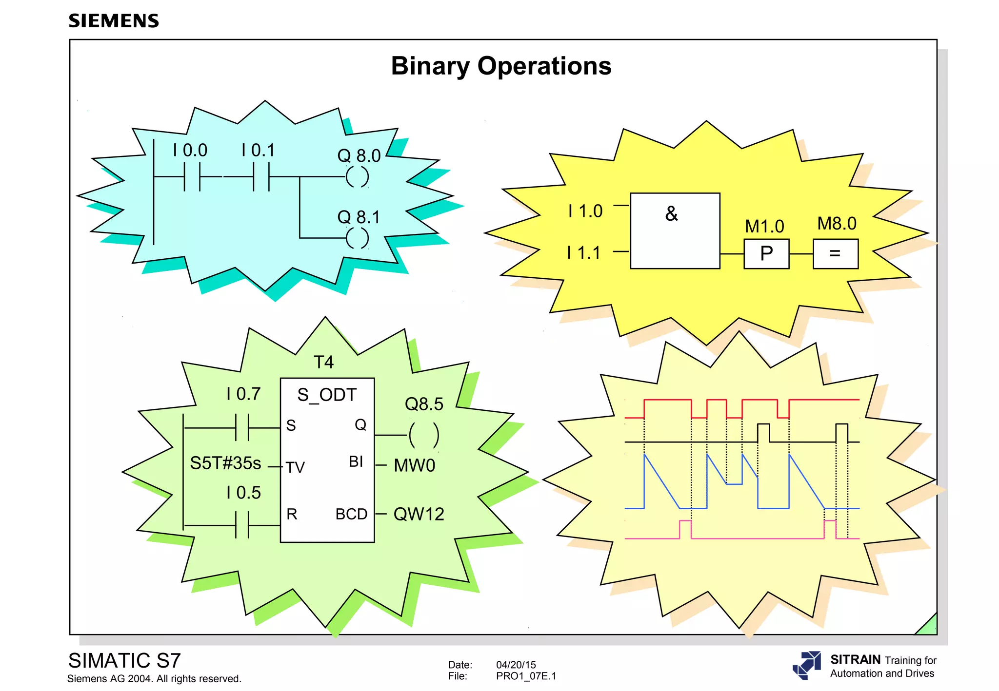
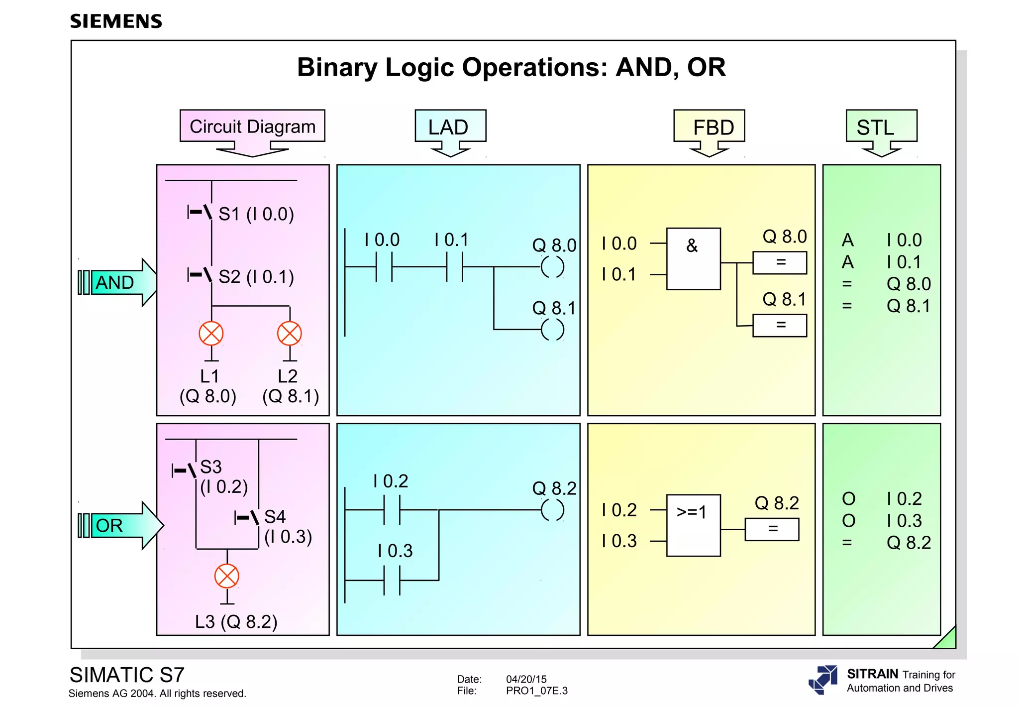
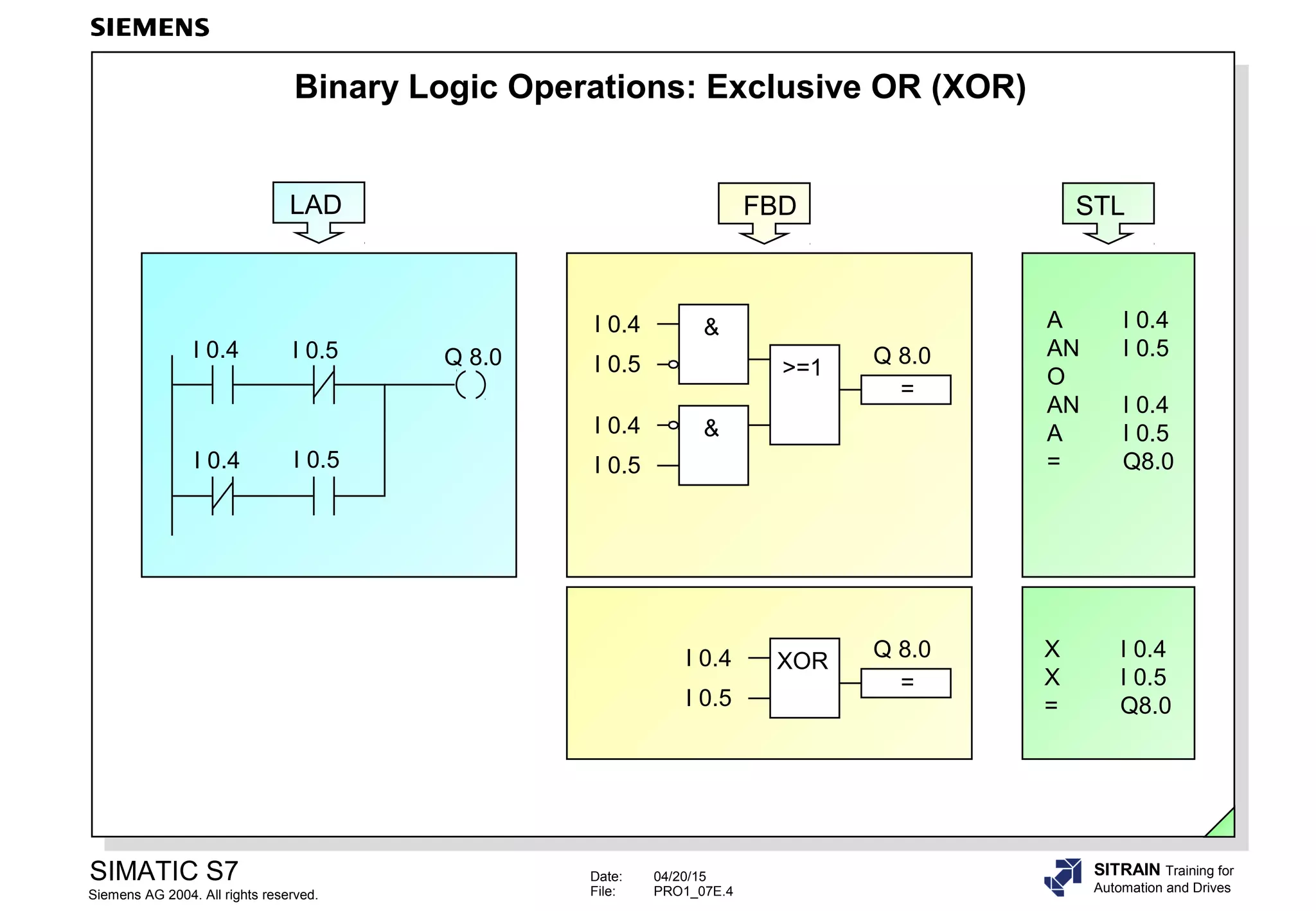
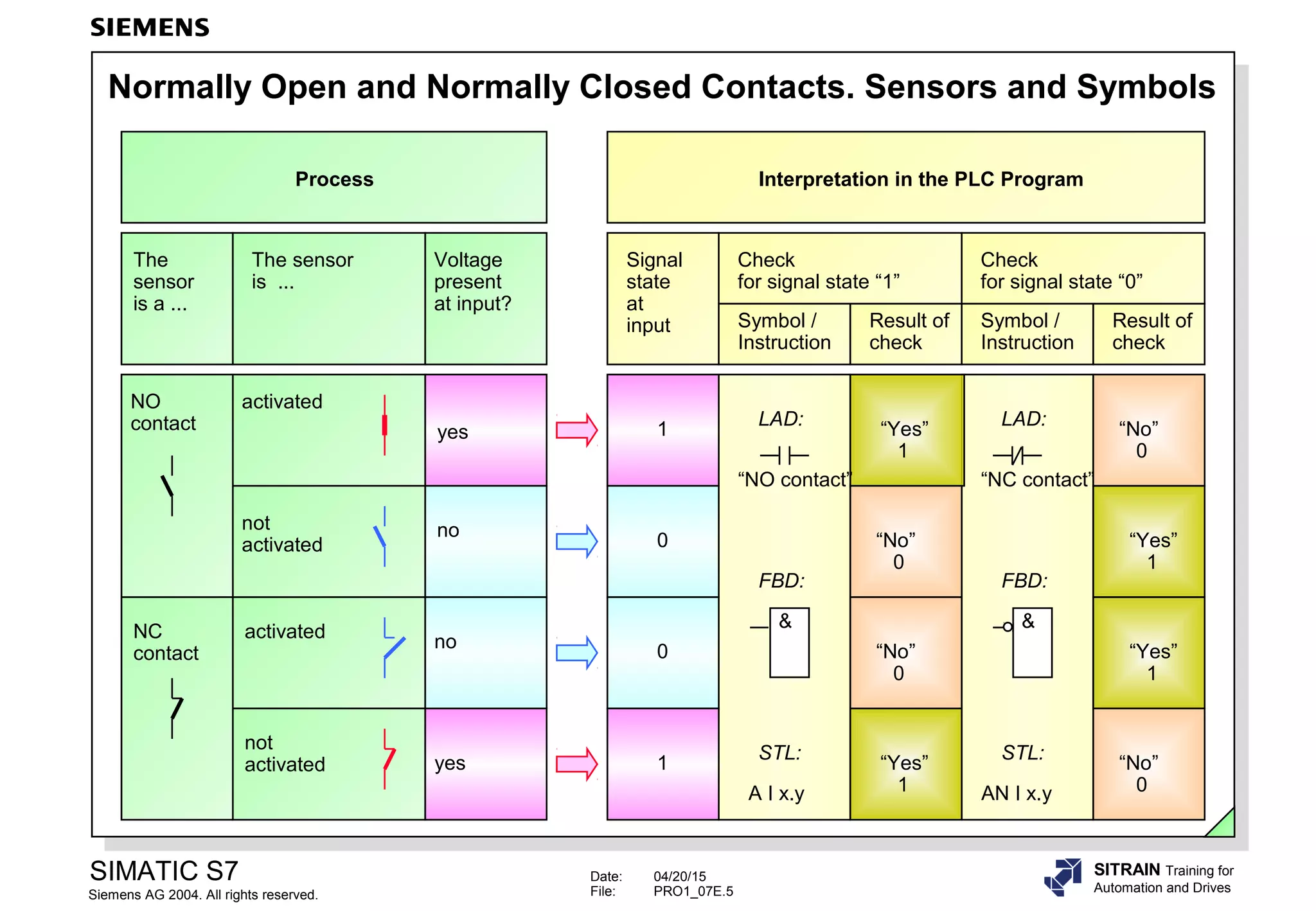
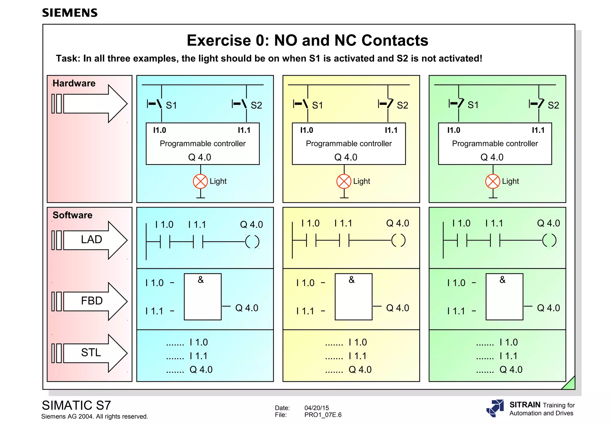
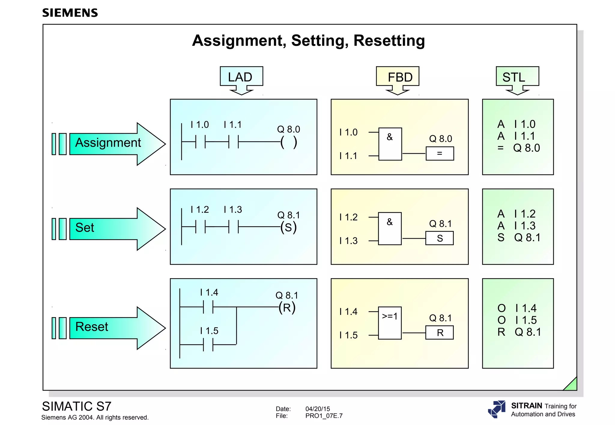
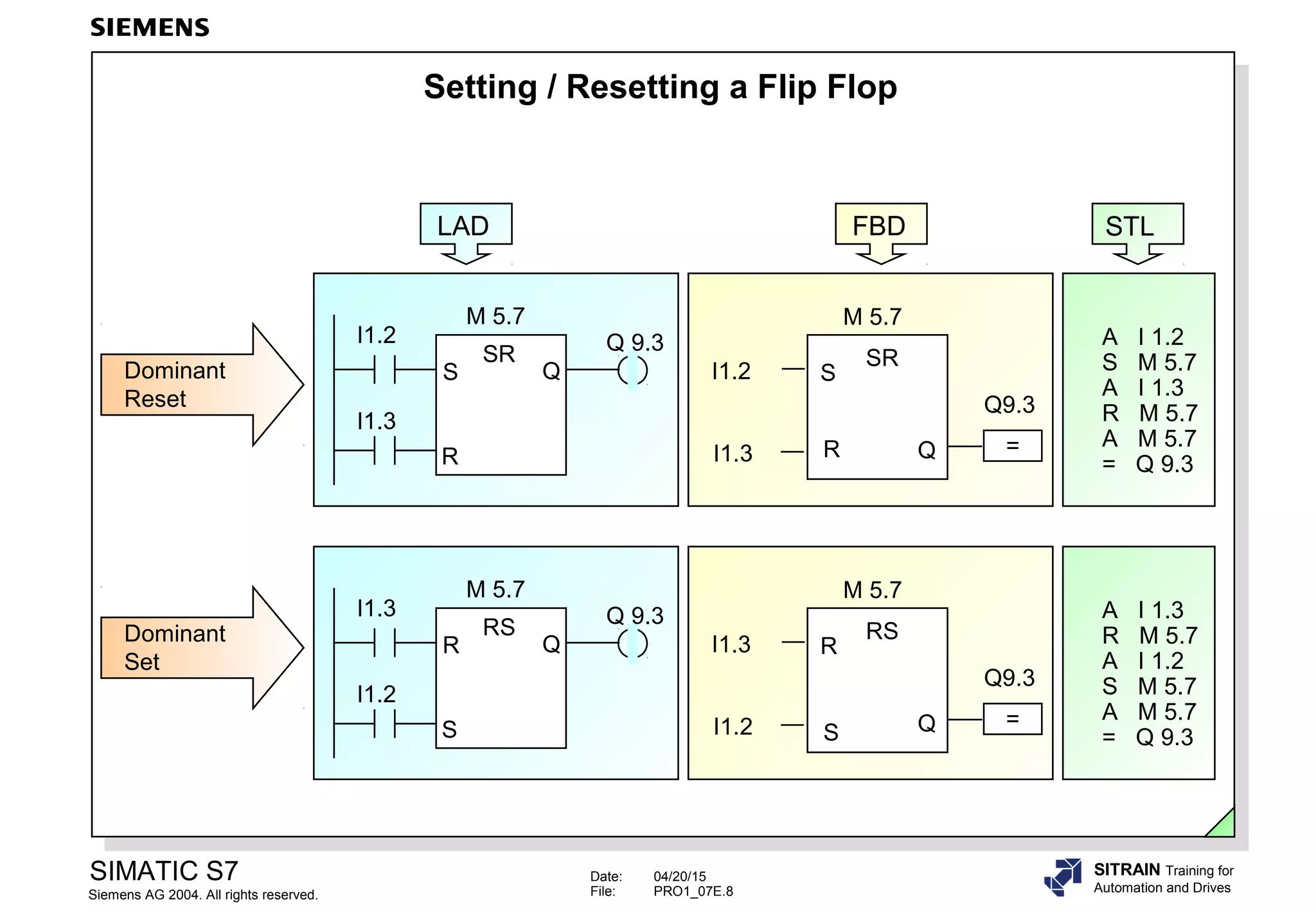
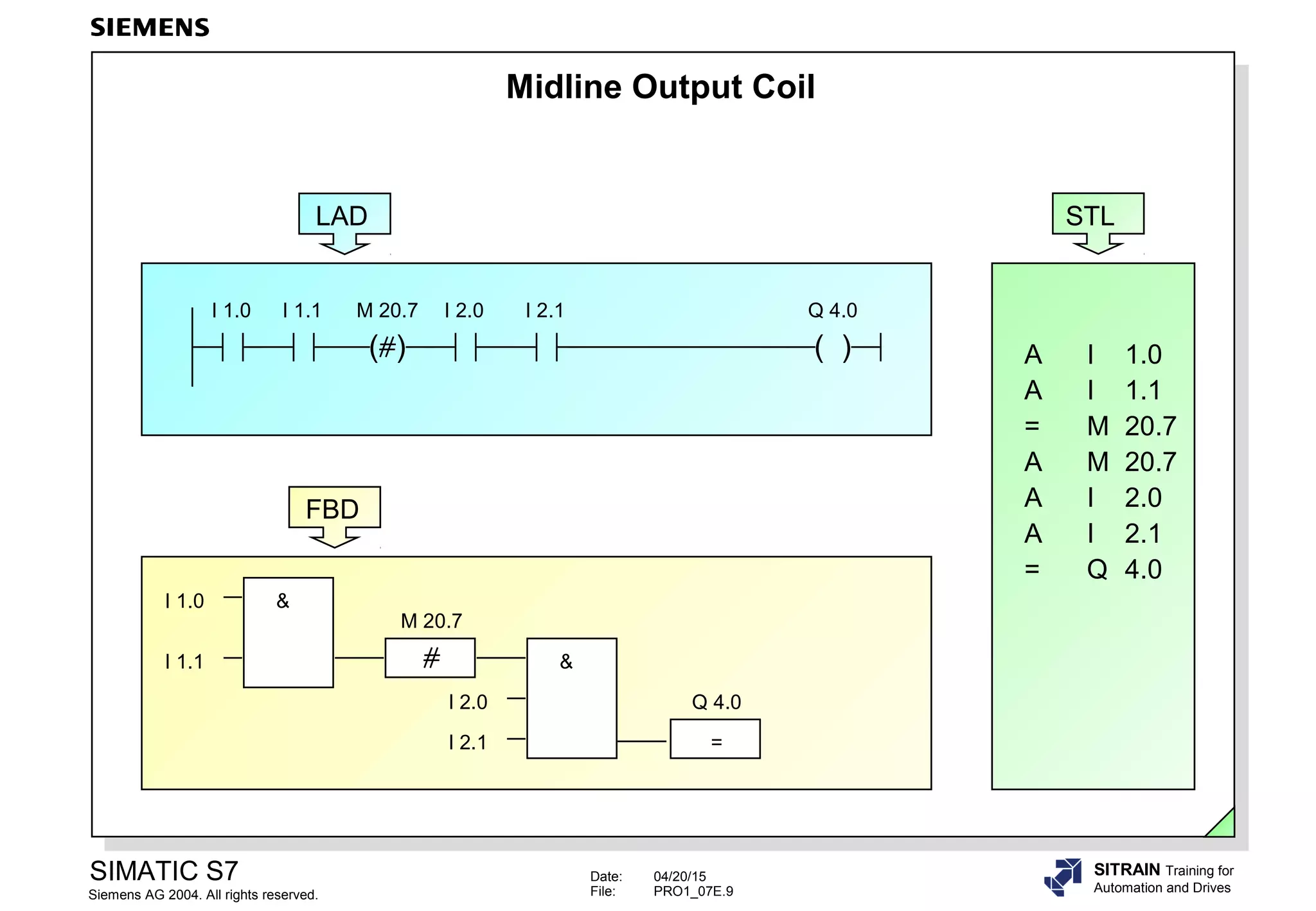
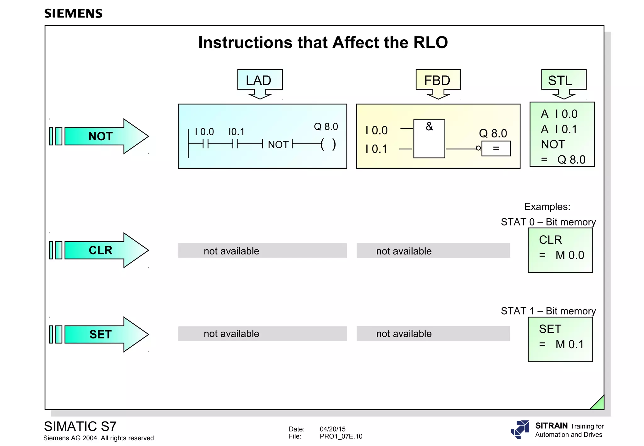
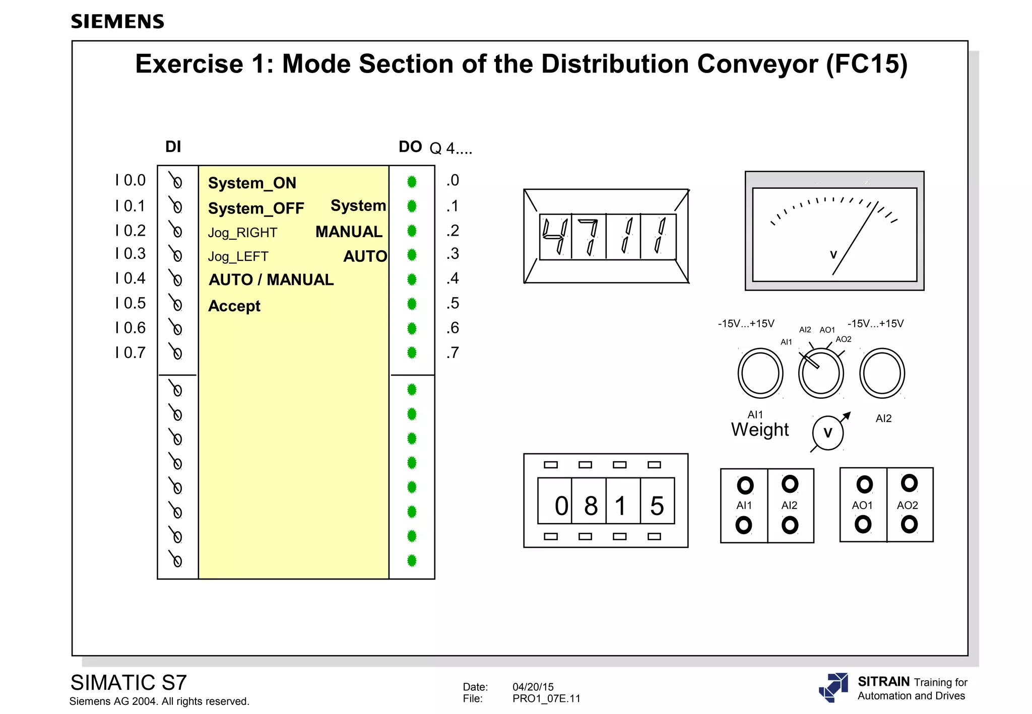
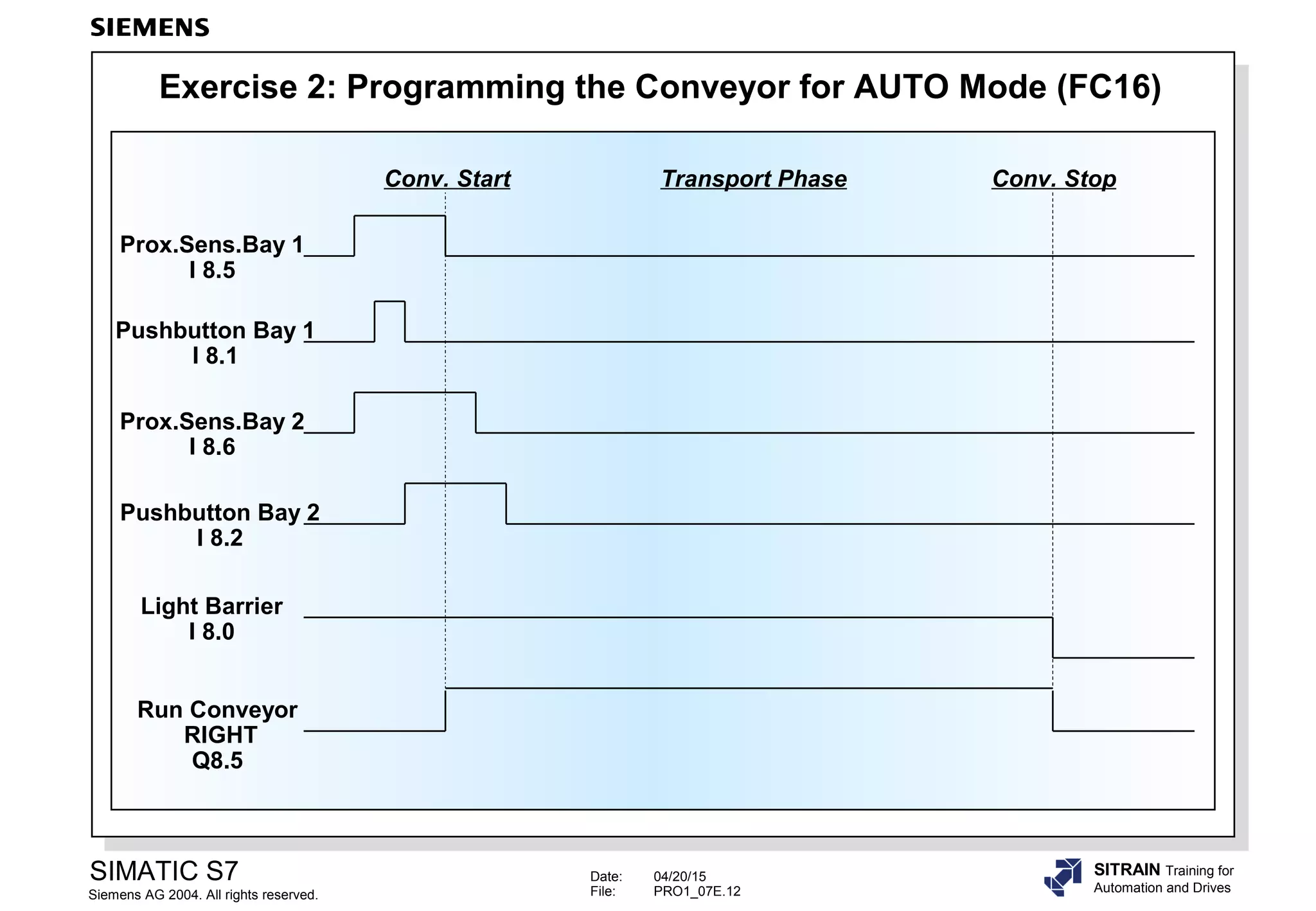
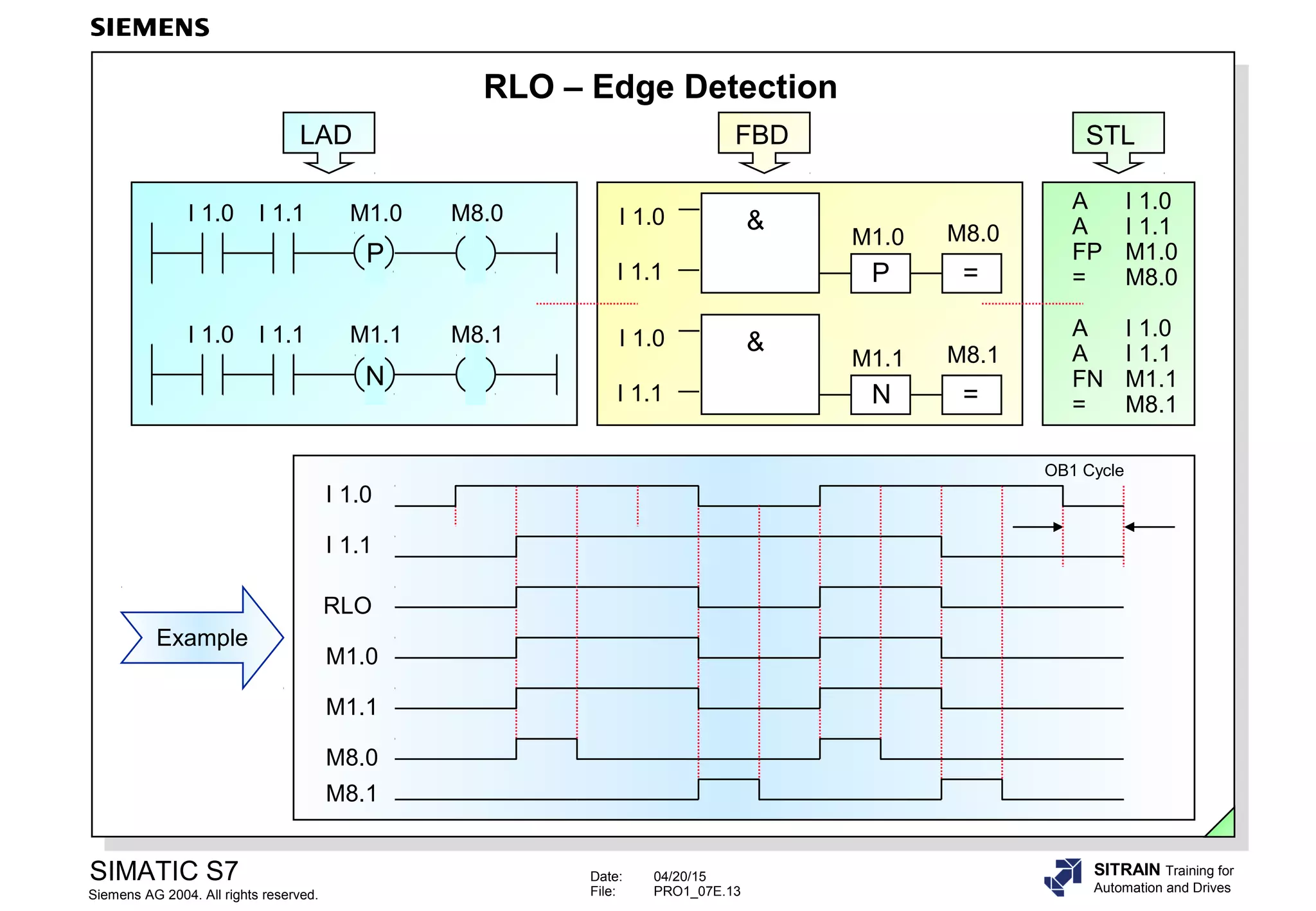
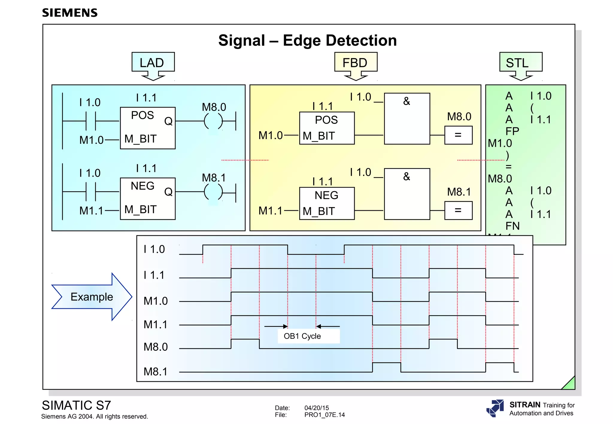
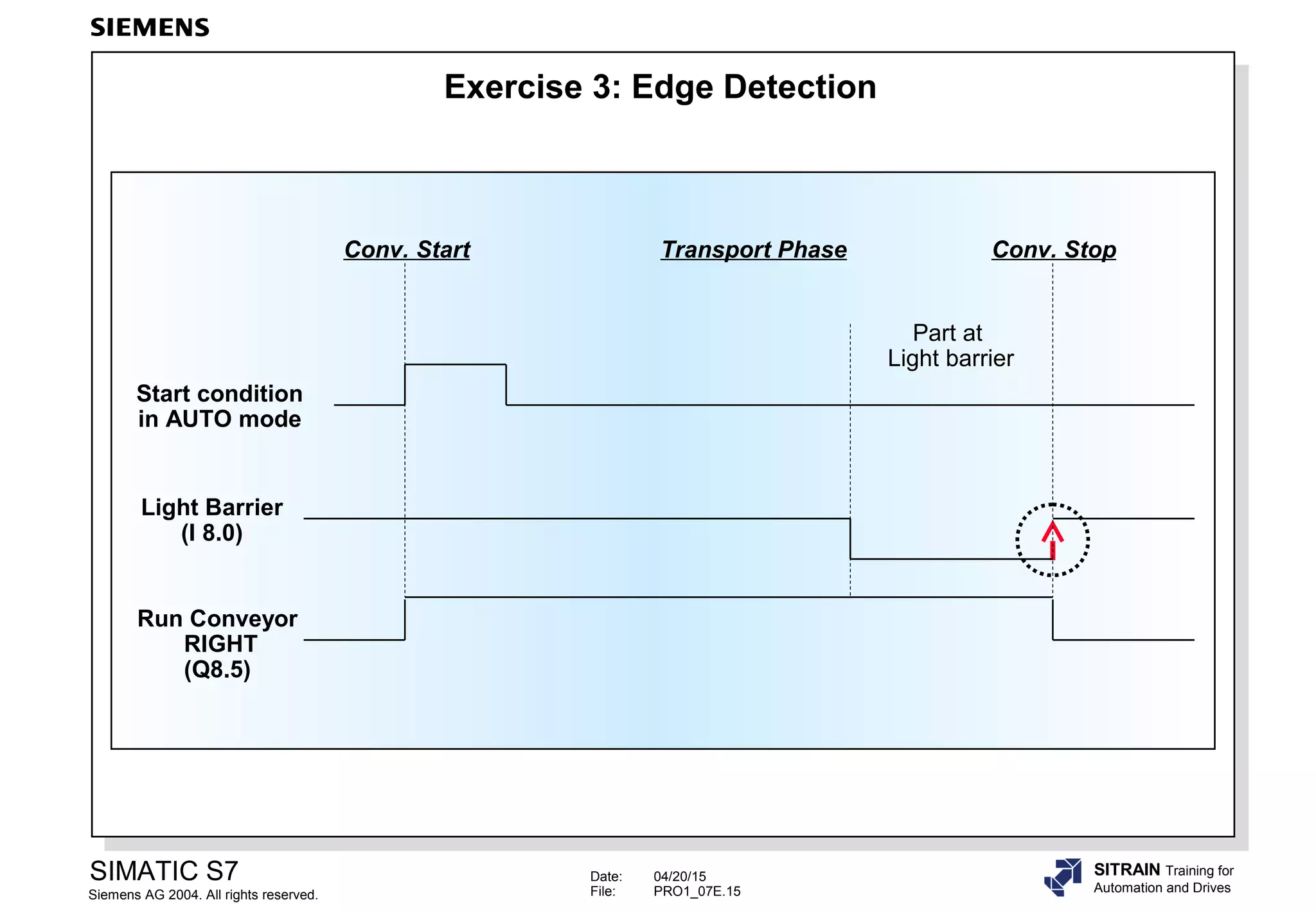
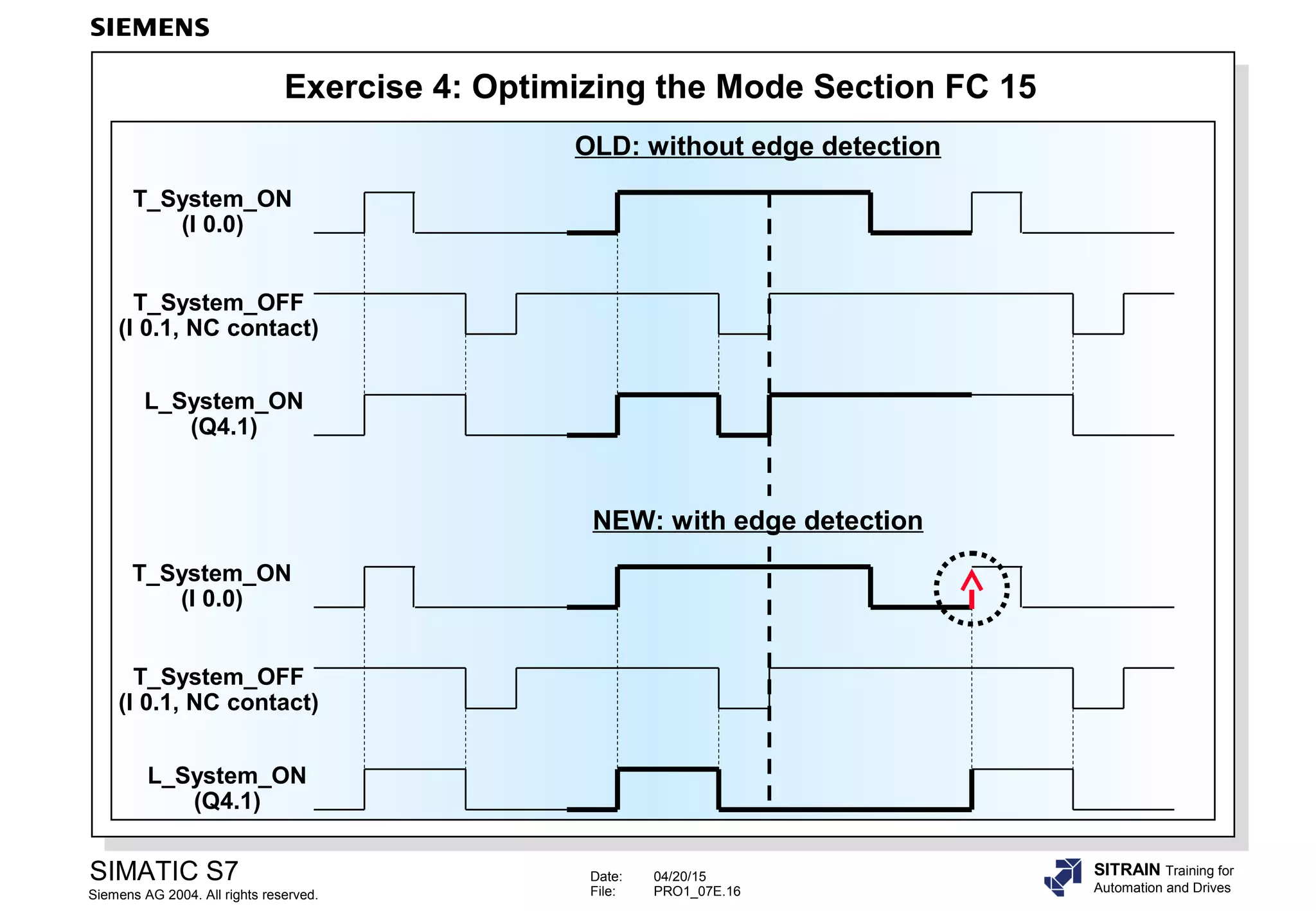


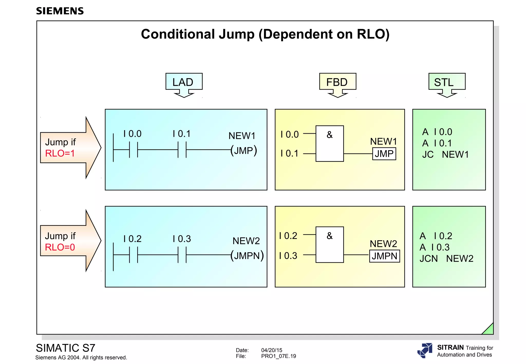

The document is a training manual for binary logic operations in a SIMATIC S7 PLC. It covers topics such as AND, OR, XOR logic operations; normally open and normally closed contacts; setting and resetting flip flops; and edge detection. It includes examples of logic operations programmed in Ladder Logic (LAD), Function Block Diagram (FBD), and Statement List (STL) languages. It also provides exercises for trainees to program logic functions for conveyor control applications.


