S1 Mechanical Pedal Speed Limiter
•
0 likes•392 views

The speed limiter is the world's highest level of generalization, security, advanced a car speed limiter.

Recommended
More Related Content
What's hot
What's hot (18)
Viewers also liked
Viewers also liked (17)
Similar to S1 Mechanical Pedal Speed Limiter
Similar to S1 Mechanical Pedal Speed Limiter (20)
More from robin huang
More from robin huang (20)
Recently uploaded
Recently uploaded (20)
S1 Mechanical Pedal Speed Limiter
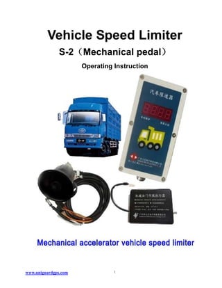
- 1. Vehicle Speed Limiter S-2(Mechanical pedal) Operating Instruction www.uniguardgps.com 1
- 2. Catalogue Product description and feature setting..............................................................................................................3 1 Introduction .............................................................................................................................................................3 2 Major role..................................................................................................................................................................3 3 Product features.....................................................................................................................................................3 4 Technical parameters ............................................................................................................................................4 5 Remote control functional description.............................................................................................................4 6 Specific operations................................................................................................................................................4 6.2 alarm speed setting....................................................................................................................................5 6.3 10 m pulse setting...............................................................................................................................5 6.3.1 Automatic learning ..........................................................................................................................5 6.3.2 Study manual............................................................................................................................................5 7 System block diagram ..........................................................................................................................................5 www.uniguardgps.com 2
- 3. Product description and feature setting 1 Introduction The speed limiter is the world's highest level of generalization, security, advanced a car speed limiter. 2 Major role At present, the clear provisions of the state, the large motor vehicles must be installed car speed limiter. The governor is used to restrict the main function of the vehicle driving too fast. Within the scope of the safe speed to drive. The speed limit speed limiter threshold can management personnel to adjust themselves can be from 0 to 100 kilometers per hour within the scope of regulation. Suitable for all kinds of motor vehicles at home. This exercise in setting speed limits if vehicle speed range, the safety of the drivers can free action accelerator. When to set the speed limit value, the speed limit switch, microcomputer chip current speed, the real-time testing and control ECU system force decreasing throttle, speed limiter adjust according to the speed and acceleration is intelligent, avoid the speed beyond the speed limit, and the rate of limited value when there is sound, flashing alarm to remind. Such as the speed limit value is set at 80 km/h, and then the speed will not exceed 80 km/h, and sound and light alarm when at 80 km/h. 3 Product features 1. Remote control setting function, you can set the parameters, the driver can't change the speed limit value, managers hold the remote control to have the right to modify; 2. Widely applicable, can be used in the electronic accelerator pedal car on 12 v ~ 24 v. Light volumes, simple installation, use the full floating shock design, good seismic performance; 3. with the power cord for short circuit design, built-in over current protection circuit, strong stability; 4. Free maintenance, no mechanical contact, electronic control mechanical design features, installation at a time, a lifetime; 5. Can force the speed limit speed, idling away, do not affect a torque and horsepower, safe speed limit, also can open voice and light warning; 6. Limit speed down forcibly; within the speed limit the accelerator can free action; 7. With functions of intelligent learning step speed table, can be connected directly to all kinds of vehicle speed table, simple installation, also can equipped with GPS speed or speed sensor; www.uniguardgps.com 3
- 4. 8. To memory live all kinds of parameters, a set of lifetime effective; 9. DC12V ~ 24 v voltage range. 10. Work small power consumption, is only 5 w. 4 Technical parameters Application temperature: -35℃-50℃, relative humidity is not more than90% should be able to work properly . Road three-stage and three-stage criteria to be applied above the highway. Speed range: 40-120 km/h Speed limit deviation: ± 5 km/h. Carrying capacity: NXS-1A speed limiter not less than 600N. The operating voltage range of the products: 9-28V Low temperature resistance:-40 ℃ Temperature resistance: + 85 ℃ Vibration-resistance performance indicators: frequency 20-50HZ acceleration 1 g Electromagnetic compatibility: the Group pulse voltages up to 6000V Rated power consumption 5W; 5 Remote control functional description The keys function Operate description 1 add Make the data on the function set up 2 reduce Make the data on the function reduce down 3 4 Speed setting Long press 1 second display, equipped with police lights speed, press again to exit SetupB, then press 1 second display, set the secondary speaker speed, press again to exit Setup Km/h 5 Volume setting Keep one second to enter setting, once again is to exit the setting. 6 Ten meters set, learning Pressing keep six seconds to enter setting, once again is to exit the setting 6 Specific operations 6.1 Lock time setting Power on the system, digital control shows the current speed, as long as: various parameters have been c hosen, such as the number pulses to walk 10 meters (through acquisition), two alarming speeds. Power o www.uniguardgps.com 4
- 5. n the system, digital control shows the current speed, as long as: various parameters have been chosen, such as the number of pulses to walk 10 meters (through acquisition), two alarming speeds. 6.2 alarm speed setting Long press on the remote control to the "4" button for 1 seconds (more than two seconds from ' exit the se tting State), can enter the speed alarm level setting, digital display, "A00.0", the speaker makes a "beep" s ound with a tip, "a" indicates the current speed setting for alerts, the next three digits for the speed warnin g alarm. Unit is "km/h". Press the "1" key and the "2" key, could be reduced by increased ring to set the sp ecific speed. Short press the "4" key, exit speed level is set; the system will automatically save the setting s data. Once again, long press the "4" key for one second to enter the speed can be set two, digital displa y, "B00.0", the speaker makes a "beep" sound with a hint, the "b" represents the current state of limit spee d setting, press the "1" key and the "2" key, you can increase or decrease the set speed. Short press the " 4" key, exit speed limits the speed settings, the system will automatically save the settings data. Speed le vel and speed levels set, available through the "4" button sets the cycle operation. Note: when entering system setup process, must be pressed within 3 seconds remote control "1" add key or the "2" sets the reduction key, otherwise the system automatically after 3 seconds to exit the setting pro cess. 6.3 10 m pulse setting 6.3.1 Automatic learning In a 10 meters distance road , long by remote control "6" key a seconds, buzzer issued "beep" a sound for sound tips, digital tube displayed displayed once reads to of 10 meters pulse number, forklift began walki ng, during digital tube displayed current reads to of corresponding of pulse, 10 meters arrived , forklift stop walking, digital tube displayed for current reads to of pulse number, again by "6" key, until digital tube all extinguished release, system automatically save the pulse number, buzzer while issued "beep" A loud be ep, NIXIE tube again to show the current speed . (Note: 10meters pulse inputs accurately determines the accuracy of the speeding alarm speed, so 10 m distance must be, the forklift to line out 10 meters away) 6.3.2 Study manual When the vehicle speed reaches or exceeds a set speed limit, speed setting a time, automatically limiting circuit, speed dropped until lifting the speed limit. 7 System block diagram www.uniguardgps.com 5
- 6. 8 Installation notes: 1.Please follow the wiring instructions electrical connection, otherwise, people randomly change the configurati on control module will burn. 2.In the frequent acceleration and deceleration, vehicle speed limit on many sections do not use this functionExcept in failure occurred during exercise, drivers can remove speed limit cabl e, the other drives disassembly without permission is strictly prohibited, there, we do not assume responsibility for the consequences. Speed limiting function testing when required stabilizing vehicle speed, accurate speed values, in the process b ecause the inertia factor of acceleration and deceleration, speed value will be biased. Rain, fog, snow, weather, please does not use the speed limit function! Snowy and slippery use danger! When the vehicle after speeding, starting the servo speed limit work f orce decreases the throttle on the throttle servo system, drivers not to stomp on the accelerator pedal. www.uniguardgps.com 6