SlideShare a Scribd company logo
1 of 7
Download to read offline
US 20100019506A1
(19) United States
1mA0620.}58921.
0%NJ102S
U:."m03NDb.b.UHPPon00
n001tac01lbHPn001tac01l0..My
tnlm3t
amPGm
Publication Classi?cation
(51) Int. Cl.
(54) POWER SYSTEM HAVING AN AMMONIA
FUELED ENGINE
(2006.01)
(2006.01)
F023 63/04
F023 43/00
F02D 41/00
(75) Inventors: Weidong Gong, Dunlap, IL (US);
Martin Leo Willi, Dunlap, IL (US)
(2006.01)
Correspondence Address: _ _
CATERPILLAR/FINNEGAN, HENDERSON, (52) US. Cl. 290/1 A, 123/1 A, 123/672
L.L.P.
(57) ABSTRACT
A poWer system is disclosed. The poWer system may include
an output device and a combustion engine con?gured to com
901 New York Avenue, NW
WASHINGTON, DC 20001-4413 (US)
(73) Assignee: Caterpillar Inc. _ _ _
bust ammoma as a pr1mary fuel to generate mechanical poWer
(21) App1_ NO; 12/219,418 directed to the output device. The poWer system may also
include an electrical unit con?gured to supplement the
mechanical poWer directed to the output device.(22) Filed: Jul. 22, 2008

200120
112
116
110A’
130
AIR
Patent Application Publication Jan. 28, 2010 Sheet 1 0f 2 US 2010/0019506 A1
F
I
I
O
00
E
8| o O
‘r

o °°°°°
°°| :0:
O//r.
20
US 2010/0019506 A1
POWER SYSTEM HAVING AN AMMONIA
FUELED ENGINE
TECHNICAL FIELD
[0001] The present disclosure is directed to a power system
and, more particularly, to a poWer system having an ammonia
fueled engine.
BACKGROUND
[0002] Increasing concerns on global Warming have given
impetus to the search for Zero-carbon fuels for use in com
bustion engines. Characteristics of ammonia fuel, such as
Zero CO2 emission, relatively high energy density, Well-es
tablished production infrastructure, and competitive cost,
have made ammonia an attractive alternative fuel for com
bustion engines. When ammonia is combusted, the combus
tionproduces a ?ame With a relatively loW propagation speed.
In other Words, the combustion rate of ammonia is loW. This
loW combustion rate of ammonia causes combustion to be
inconsistent under loW engine load and/or high engine speed
operating conditions. Most existing combustion engines that
use ammonia as engine fuel typically require a combustion
promoter (i.e., a second fuel such as gasoline, hydrogen,
diesel, etc.) for ignition, operation at loW engine loads and/or
high engine speed. HoWever, the requirement forthe combus
tion promoter fuel ?uctuates With varying engine loads and
engine speed, Which can cause control issues. Furthermore,
the use of dual fuels generally requires dual fuel storage
systems, dual delivery systems, and dual injection systems,
thus adding additional Weight, complexity, and cost to the
engine system. To eliminate the use of combustion promoter
fuel, combustion engines that burn ammonia alone as engine
fuel have been explored.
[0003] One such combustion engine that burns only ammo
nia as a fuel is described in US. Pat. No. 3,455,282 (the ’282
patent) issued to T. J. Pearsall on Sep. 25, 1967. The ’282
patent describes a combustion engine having a substantially
spherical combustion chamber for combusting ammonia
alone as fuel. To ensure performance at loW load conditions,
the combustion engine uses highly compressed ammonia
With a compression ratio of the order of 12:1 to 16: 1. Due to
the loW rate of ?ame propagation, performance of the dis
closed ammonia-fueled combustion engine decreases at
engine speeds above 3000 rpm. As such, an added fuel such
as hydrogen is still needed to improve performance at speeds
above 3000 rpm.
[0004] Although the combustion engine ofthe ’282 patent
may seem promising in eliminating the need for combustion
promoter fuel, such a combustion engine may still have lim
ited applicability. In particular, the engine ofthe ’282 patent
may still perform poorly in applications Where engine speeds
are high Without the use of a second fuel.
[0005] The poWer system of the present disclosure is
directed toWard improvements in the existing technology.
SUMMARY
[0006] One aspect ofthe present disclosure is directed to a
poWer system. The poWer system may include an output
device and a combustion engine con?gured to combust
ammonia as a primary fuel to generate mechanical poWer
directed to the output device. The poWer system may also
include an electrical unit con?gured to supplement the
mechanical poWer directed to the output device.
Jan. 28, 2010
[0007] Another aspect ofthe present disclosure is directed
to a method of operating a poWer system. The method may
include combusting ammonia as a primary fuel to generate
mechanical poWer directed to drive the poWer system. The
method may also include electrically supplementing the
mechanical poWer directed to drive the poWer system.
BRIEF DESCRIPTION OF THE DRAWINGS
[0008] FIG. 1 is a diagrammatic illustration of an exem
plary disclosed machine; and
[0009] FIG. 2 is a schematic illustration of an exemplary
disclosed poWer system that may be used With the machine of
FIG. 1.
DETAILED DESCRIPTION
[0010] FIG. 1 diagrammatically illustrates an exemplary
machine 10. Machine 10 may be a mobile machine such as a
vehicle, or a stationary machine such as a pump, a poWer
generator, etc. For illustrative purposes, machine 10 is sche
matically shoWn as a vehicle in FIG. 1.
[0011] Machine 10 may include a poWer system 20 con?g
ured to provide poWer to drive machine 10. PoWer system 20
may include a combustion engine 30 con?gured to combust
ammonia as a primary fuel and produce mechanical poWer
used to drive machine 10. For the purpose ofthis disclosure,
a fuel may be regarded as a “primary” fuel if the fuel consti
tutes, for example, at least 80% ofthe total fuel directed into
and combusted by combustion engine 30. In some embodi
ment, ammonia fuel may constitute 90%-95%, or even as
high as 100% (ammonia being the only fuel) ofthe total fuel
combusted by combustion engine 30. It is understood that the
percentage used here may be based on mass, volume, or
thermal energy of the fuel. The fuel directed into and com
busted by combustion engine 30 may, in some situations,
include additives, such as detergents, lubricants, ethanol, etc.
[0012] Machine 10 may also include a drivetrain 40
coupled to and driven by combustion engine 30. Drivetrain 40
may include a transmission 60 con?gured to receive the
mechanical poWer produced by combustion engine 30 and to
transmit the mechanical poWer to an output device 70, and an
electrical unit 50 con?gured to convert a portion of the
mechanical poWerproducedby combustionengine 30 to elec
trical poWer selectively used to drive output device 70 during
particular operating conditions. Output device 70 may be
con?gured to output the mechanical poWer to drive a load 80.
In the embodiment shoWn in FIG. 1, load 80 may be one or
more traction devices con?gured to propel machine 10, for
example, Wheels.
[0013] As shoWn in FIG. 2, combustion engine 30 may
include one or more cylinders 90 at least partially de?ning
one or more combustion chambers. Combustion engine 30
may also include a fuel supply system 110 con?gured to
provide ammonia fuel to cylinders 90, and an exhaust system
120 con?gured to treat exhaust received from cylinders 90.
[0014] Fuel supply system 110 may supply ammonia to
cylinders 90 for combustion. Fuel supply system 110 may
include an onboard supply 112 of ammonia, and a control
device 116, for example a valve, con?gured to adjust an
amount of ammonia supplied to combustion engine 30.
Ammonia may be supplied directly to cylinders 90 or, in some
embodiments, ?rst mixed With combustion air directed into
an intake manifold 130 of combustion engine 30. It is con
templated that, When a ?uid in addition to ammonia is
US 2010/0019506 A1
directed into combustion engine 30, fuel supply system 110
may include additional onboard supply and/or delivery
devices, if desired.
[0015] Exhaust system 120 may include an exhaust mani
fold 140 connected With cylinders 90. The exhaust produced
by combustion engine 30 may be directed from cylinders 90
through exhaust manifold 140 to the atmosphere. Exhaust
system 120 may also include one or more exhaust treatment
devices in communication With exhaust manifold 140 to treat
the exhaust prior to discharge. For example, exhaust system
120 may include a ?rst oxidation catalyst 150, a constituent
reducing device 160, and a second oxidation catalyst 170. It is
contemplated that exhaust system 120 may include additional
or different exhaust treatment devices than shoWn in FIG. 2, if
desired.
[0016] First oxidation catalyst 150 may receive exhaust
exiting combustion engine 30. The exhaust produced from
combusting ammonia may contain NO,C (such as NO and
N02). First oxidation catalyst 150 may oxidiZe NO to convert
NO into N02, thereby, changing a ratio ofNOzNO2 Within the
exhaust. In some embodiments, for doWnstream constituent
reducing device 160 to perform optimally, the ratio of
NOzNO2 should be about 1:1. It is contemplated that exhaust
system 120 may also include a particulate ?lter (not shoWn)
con?gured to reduce particulate matter in the exhaust. If
included, the particulate ?lter may be located upstream or
doWnstream of ?rst oxidation catalyst 150, or may be inte
grated With ?rst oxidation catalyst 150 to form a single unit.
[0017] Constituent reducing device 160 may be con?gured
to reduce a constituent of the exhaust, and may be located
doWnstream of ?rst oxidation catalyst 150. In one embodi
ment, constituent reducing device 160 may include a selective
catalytic reduction (SCR) device con?gured to reduce NO,C in
the exhaust using a reducing agent, such as ammonia, urea,
diesel fuel, etc. Since ammonia may be combusted as a pri
mary engine fuel, it is possible that there is suf?cient
unburned residual ammonia Within the exhaust to reduce NO,C
Within the SCR device Without additional reductant being
injected. Therefore, an injection device normally needed for
injecting the reducing agent may be eliminated. In some
embodiments, constituent reducing device 160 may be inte
grated With ?rst oxidation catalyst 150 as a single component.
[0018] Second oxidation catalyst 170 may be provided at a
doWnstream end of exhaust system 120, for example, doWn
stream of constituent reducing device 160. Second oxidation
catalyst 170 may be con?gured to oxidiZe one or more con
stituents of the exhaust after the exhaust has already been
treated by other upstream devices, and before the exhaust is
released to the atmosphere. In some embodiments, second
oxidation catalyst 170 may be con?gured to oxidiZe excess
ammonia remaining Within the exhaust.
[0019] A control system 180 may be associated With
exhaust system 120, to regulate operations thereof. Control
system 180 may include a controller 190 and a sensor 200 in
communication With controller 190. Sensor 200 may be con
?gured to measure an amount ofan exhaust constituent Within
the exhaust, e.g., NO,C or residual ammonia fuel Within the
exhaust. Based on signals from sensor 200, controller 190
may adjust control device 116 to change the amount of
ammonia supplied to combustion engine 30, thereby control
ling constituent emissions in the exhaust.
[0020] Controller 190 may be a stand-alone controller or an
existing engine control module, and may include a control
algorithm for controlling various devices including sensor
Jan. 28, 2010
200 and control device 116. It is contemplated that controller
190 may be associated With other devices or systems, such as
electrical unit 50, if desired.
[0021] Sensor 200 may be disposed at any suitable location
Within exhaust system 120, for example, doWnstream ofcon
stituent reducing device 160 and upstream of second oxida
tion catalyst 170, or doWnstream ofsecond oxidation catalyst
170. In some embodiments, sensor 200 may include tWo
separate sensors, a NO,C sensor con?gured to measure an
amount of NO,C Within the exhaust, and an ammonia sensor
con?gured to measure an amount of ammonia Within the
exhaust. Sensor 200 may generate a signal indicative of an
amount ofNO,C and/or ammonia Within the exhaust and may
direct the signal to controller 190.
[0022] Electrical unit 50 may be poWered by combustion
engine 30, and may electrically supplement the mechanical
poWer directed from electrical unit 50 to output device 70.
Electrical unit 50 may include, among other things, a genera
tor 210, a poWer storage 220, for example a battery, and an
electric motor 230. Generator 210 may be drivingly coupled
With combustion engine 30 through a ?rst mechanical link
212, and electrically connected With poWer storage 220 via a
?rst electrical line 214. PoWer storage 220 may be further
connected With electric motor 230 via a second electric line
224. Electric motor 230 may be mechanically coupled With
output device 70 through a second mechanical link 232.
Although not shoWn, it is contemplated that electrical unit 50
may be connected With and regulated by controller 190, if
desired.
[0023] Transmission 60 may be any suitable (e.g., manual
or automatic) transmission knoWn in the art. Transmission 60
may be mechanically coupled With combustion engine 30 to
receive mechanical poWer generated by combustion engine
30 and to transmit the received mechanical poWer to output
device 70 through a plurality ofgears, rotating shafts, hydrau
lic circuits, etc.
INDUSTRIAL APPLICABILITY
[0024] The disclosed ammonia fueled combustion engine
and electrical unit may be employed in poWer system appli
cations Where loW CO2 and NO,C emissions, consistent per
formance, and loW operating cost are desired. Speci?cally, by
combusting ammonia as a primary fuel, extremely loW CO2
emission, or even Zero CO2 emission, may be achieved. NO,C
emissions may also be reduced to a loW level by using
unburned residual ammonia fuel as a NOx-reducing agent in
an SCR device, Without requiring additional reductant dosing
equipment. And, by electrically supplementing mechanical
poWer directed to the poWer system, the operating range ofthe
poWer system may be expanded to loW load and high speed
situations. In addition, because the cost ofammonia as a fuel
may relativelybe loW, substantial savings may be providedby
the disclosed poWer system.
[0025] Referring to FIG. 1, poWer system 20 may generate
poWer to drive machine 10 using combustion engine 30 and
electrical unit 50, independently and in combination.
Mechanical poWer may be generated by combustion engine
30 from combustion ofammonia as a primary fuel andmay be
directed to drive output device 70. Speci?cally, the generated
mechanical poWer may be transmitted by transmission 60
from combustion engine 30 to output device 70, Which may
further output the mechanical poWer to drive load 80 of
machine 10.
US 2010/0019506 A1
[0026] To help avoid inconsistent combustion due to the
loW combustion rate of ammonia, the operating range of
combustion engine 30 may be controllably limited. That is,
combustion engine 30 may be limited to operate Within a
predetermined engine load range, for example, 30% to 100%
of a designed maximum engine load. When a poWer demand
from poWer system 20 for driving output device 70 is outside
of the predetermined engine load range, for example, loWer
than 30% or higher than 100% of the designed maximum
engine load, electrical unit 50 may be used to electrically
supplement the mechanical poWer generated by combustion
engine 30. For example, When the poWer demand of output
device 70 is loWer than 30% ofthe designed maximum engine
load, combustion engine 30 may still Work at 30% of the
designed maximum engine load, and the excess poWermay be
absorbed by electrical unit 50 and stored in poWer storage
220. Combustion engine 30 may be shut doWn and the
demanded poWer may be provided by poWer storage 220
through electrical unit 50.
[0027] In addition, the engine speed of combustion engine
30 may be limited to help ensure consistent performance of
poWer system 20. For example, the engine speed may be
limited to about 6000 rpm. When a desired operating engine
speedexceeds thepredetermined engine speed ofcombustion
engine 30, and/or When a poWer demand from poWer system
20 exceeds the mechanical poWer generated by combustion
engine 30, electrical unit 50 may provide additional poWer to
output device 70. Because the mechanical poWer generated
by combustion engine 30 may be electrically supplemented
by electrical unit 50 under various operation conditions,
issues associated With utiliZing ammonia as a primary fuel
may be avoided.
[0028] Referring to FIG. 2, poWer system 20 may be driven
using only the electrical poWerprovided by electrical unit 50.
For example, Machine 10 may be operated in loW poWer
conditions, for example, under stop-and-go driving condi
tions in a city. The poWer demand from poWer system 20 in
these conditions may be insuf?cient (e.g., loWer than the
loWest engine load inthe predetermined engine loadrange) to
maintain consistent operation ofcombustion engine 30, even
With the assistance of electrical unit 50. In such conditions,
electrical unit 50 alone may provide poWer to poWer system
20, and combustion engine 30 may be shut doWn.
[0029] In some operating situations, the poWer demand
from poWer system 20 may be too high for electrical unit 50
alone to provide poWer for the demand, but insuf?cient for
combustion engine 30 alone to be operated consistently. In
such conditions, combustion engine 30 may still be used to
provide poWer to poWer system 20, and electrical unit 50 may
be used to intentionally increase the engine load on combus
tion engine 30 by converting a portion of the mechanical
poWer of combustion engine 30 into electrical poWer. When
poWer storage 220 reaches its full capacity, electrical unit 50
may be turned off, for example, by controller 190. In this
manner, electrical unit 50 may help ensure combustion engine
30 is operated at a load condition that is high enough for
stable, consistent, and ef?cient operation.
[0030] In some operating situations, the poWer demand
from poWer system 20 may be large enough for combustion
engine 30 to be consistently and e?iciently operated Without
assistance from electrical unit 50. That is, the load on com
bustion engine 30 may be Within the predetermined engine
load range. Under such conditions, combustion engine 30
alone may provide poWer to poWer system 20.
Jan. 28, 2010
[0031] In some operating conditions, the poWer demand
from poWer system 20 may exceed the mechanical poWer
capacity of combustion engine 30. In such conditions, elec
trical unit 50 may provide additional poWer to poWer system
20. Thus, combustion engine 30 and electrical unit 50 may
simultaneously provide poWerto poWer system 20 for driving
machine 10.
[0032] Controller 190 may control the air/fuel ratio ofcom
bustion engine 30 by adjusting, for example, the amount of
ammonia fuel directed through control device 116. An
amount ofammonia fuel in excess ofa stoichiometric amount
(i.e., equivalence ratio greater than 1.0) may be supplied to
combustion engine 30, such that residual ammonia fuel is
present Withinthe exhaust. The residual ammonia fuel may be
used as a reductant for reducing NO,C Within constituent
reducing device 160. At constituent reducing device 160, the
residual ammonia fuel may react With NO,C to convert NO,C to
nitrogen andWater. Controller 190 may analyZe the amount of
NOX, the amount of ammonia, or both measured by sensor
200, and responsively adjust the amount of ammonia fuel
supplied to combustion engine 30. With such a feedback
system, NO,C and ammonia emissions to the atmosphere may
be controlled to be beloW a predetermined level.
[0033] It Will be apparent to those skilled in the art that
various modi?cations and variations can be made to the
poWer system of the present disclosure Without departing
from the scope ofthe disclosure. Other embodiments Will be
apparent to those skilled in the art from consideration of the
speci?cation and practice of the poWer system disclosed
herein. It is intended that the speci?cation and examples be
considered as exemplary only, With a true scope of the dis
closure being indicated by the folloWing claims and their
equivalents.
What is claimed is:
1. A poWer system, comprising:
an output device;
a combustion engine con?gured to combust ammonia as a
primary fuel to generate mechanical poWer directed to
the output device; and
an electrical unit con?gured to supplement the mechanical
poWer directed to the output device.
2. The poWer system of claim 1, Wherein the combustion
engine is con?gured to combust ammonia as the only fuel to
generate the mechanical poWer directed to the output device.
3. The poWer system ofclaim 1, Wherein the electrical unit
is con?gured to supplement the mechanical poWer When a
poWer demand from the poWer system is outside of a prede
termined engine load range.
4. The poWer system ofclaim 1, Wherein the electrical unit
is con?gured to supplement the mechanical poWer When a
desired operating engine speed of the combustion engine
exceeds a predetermined engine speed.
5. The poWer system ofclaim 1, Wherein the electrical unit
includes at least one of a poWer storage, a generator, or an
electric motor.
6. The poWer system of claim 1, further including:
a sensor con?gured to measure at least one of an amount of
NO,C or an amount of residual ammonia fuel Within
exhaust produced by the combustion engine; and
a controller con?gured to adjust an amount of ammonia
supplied to the combustion engine as the primary fuel
based on at least one ofthe measured amount ofNO,C or
residual ammonia fuel.
US 2010/0019506 A1
7. The power system of claim 1, further including a con
stituent reducing device con?gured to use residual ammonia
fuel Within exhaust produced by the combustion engine to
reduce a constituent of the exhaust.
8. The poWer system of claim 7, Wherein the constituent
reducing device includes a selective catalytic reduction
device.
9. The poWer system ofclaim 7, Wherein the constituent of
the exhaust is NOX.
10. The poWer system of claim 1, Wherein the electrical
unit is con?gured to increase an engine load of the combus
tion engine When a poWer demand from the poWer system is
insuf?cient to maintain consistent operation of the combus
tion engine.
11. A method of operating a poWer system, comprising:
combusting ammonia as a primary fuel to generate
mechanical poWer directed to drive the poWer system;
and
electrically supplementing the mechanical poWer directed
to drive the poWer system.
12. The method of claim 11, further including:
converting a portion ofthe mechanical poWer into electri
cal poWer; and
directing the electrical poWer to supplement the mechani
cal poWer directed to drive the poWer system.
13. The method of claim 11, further including:
supplying ammonia fuel in excess of a stoichiometric
amount into the poWer system; and
reducing a constituent ofthe exhaust using residual ammo
nia fuel Within the exhaust.
14. The method of claim 11, further including:
measuring at least one ofan amount ofan exhaust constitu
ent or an amount of residual ammonia fuel Within the
exhaust; and
adjusting an amount ofammonia fuel supplied to the poWer
system based on the at least one ofthe measured amount
Jan. 28, 2010
ofthe exhaust constituent or the measured amount ofthe
residual ammonia fuel Within the exhaust.
15. The method of claim 11, Wherein electrically supple
menting the mechanical poWer includes electrically supple
menting the mechanical poWer When a poWer demand from
the poWer system is outside of a predetermined engine load
range.
16. The method of claim 11, Wherein electrically supple
menting the mechanical poWer further includes electrically
supplementing the mechanical poWer When a desired operat
ing engine speed exceeds a predetermined engine speed.
17. The method ofclaim 11, Wherein combusting ammonia
as the primary fuel includes combusting ammonia as the only
fuel.
18. The method ofclaim 11, further including increasing an
engine load by converting mechanical poWer generated from
combusting ammonia into electrical poWer When a poWer
demand from the poWer system is insuf?cient to sustain con
sistent combustion of the ammonia.
19. A machine, comprising:
a traction device con?gured to propel the machine;
an onboard supply of ammonia fuel;
a combustion engine con?gured to combust the ammonia
fuel as a primary fuel and generate mechanical poWer
directed to the traction device;
an electrical unit poWered by the combustion engine to
electrically supplement the mechanical poWer directed
to the traction device; and
a constituent reducing device con?gured to use residual
ammonia fuel from exhaust exiting the combustion
engine to reduce a constituent ofthe exhaust.
20. The machine ofclaim 19, Wherein the electrical unit is
con?gured to supplement the mechanical poWer When a
poWer demand from a poWer system is outside of a predeter
mined engine load range, or When a desired operating engine
speed exceeds a predetermined engine speed.
* * * * *

More Related Content

Viewers also liked

Patent Litigation Analysis for Golden Technology, Inc. - Sample report by Max...
Patent Litigation Analysis for Golden Technology, Inc. - Sample report by Max...Patent Litigation Analysis for Golden Technology, Inc. - Sample report by Max...
Patent Litigation Analysis for Golden Technology, Inc. - Sample report by Max...MaxVal Group, Inc.
 
Patent Litigation Analytics - Report on Judges in 2014 cases
Patent Litigation Analytics - Report on Judges in 2014 casesPatent Litigation Analytics - Report on Judges in 2014 cases
Patent Litigation Analytics - Report on Judges in 2014 casesMaxVal Group, Inc.
 
Analysis of Eye End of Knuckle Joint using ANSYS
Analysis of Eye End of Knuckle Joint using ANSYSAnalysis of Eye End of Knuckle Joint using ANSYS
Analysis of Eye End of Knuckle Joint using ANSYSArshad Habib Khan
 
Mechanical ventilation in COPD Asthma drtrc
Mechanical ventilation in COPD Asthma drtrcMechanical ventilation in COPD Asthma drtrc
Mechanical ventilation in COPD Asthma drtrcchandra talur
 
Nokia vs iphone Case Study and iPhone PPT template
Nokia vs iphone Case Study and iPhone PPT templateNokia vs iphone Case Study and iPhone PPT template
Nokia vs iphone Case Study and iPhone PPT templateRobin Sargent
 
Patent infringement case
Patent infringement casePatent infringement case
Patent infringement casePriyanka Nayak
 
Sample copyright case study
Sample copyright case studySample copyright case study
Sample copyright case studyMark Lushenko
 
Louis vuitton Vs. Google
Louis vuitton Vs. GoogleLouis vuitton Vs. Google
Louis vuitton Vs. GoogleAnuradha Sajwan
 

Viewers also liked (9)

Patent Litigation Analysis for Golden Technology, Inc. - Sample report by Max...
Patent Litigation Analysis for Golden Technology, Inc. - Sample report by Max...Patent Litigation Analysis for Golden Technology, Inc. - Sample report by Max...
Patent Litigation Analysis for Golden Technology, Inc. - Sample report by Max...
 
Patent Litigation Analytics - Report on Judges in 2014 cases
Patent Litigation Analytics - Report on Judges in 2014 casesPatent Litigation Analytics - Report on Judges in 2014 cases
Patent Litigation Analytics - Report on Judges in 2014 cases
 
Analysis of Eye End of Knuckle Joint using ANSYS
Analysis of Eye End of Knuckle Joint using ANSYSAnalysis of Eye End of Knuckle Joint using ANSYS
Analysis of Eye End of Knuckle Joint using ANSYS
 
Mechanical ventilation in COPD Asthma drtrc
Mechanical ventilation in COPD Asthma drtrcMechanical ventilation in COPD Asthma drtrc
Mechanical ventilation in COPD Asthma drtrc
 
Modeling and fem analysis of knuckle joint
Modeling and fem analysis of knuckle jointModeling and fem analysis of knuckle joint
Modeling and fem analysis of knuckle joint
 
Nokia vs iphone Case Study and iPhone PPT template
Nokia vs iphone Case Study and iPhone PPT templateNokia vs iphone Case Study and iPhone PPT template
Nokia vs iphone Case Study and iPhone PPT template
 
Patent infringement case
Patent infringement casePatent infringement case
Patent infringement case
 
Sample copyright case study
Sample copyright case studySample copyright case study
Sample copyright case study
 
Louis vuitton Vs. Google
Louis vuitton Vs. GoogleLouis vuitton Vs. Google
Louis vuitton Vs. Google
 

Similar to Caterpillar ammonia engine patent power production microgrids

ca1233379a1-hydrogen-gas-injection-for-internal-combustion-engine.pdf
ca1233379a1-hydrogen-gas-injection-for-internal-combustion-engine.pdfca1233379a1-hydrogen-gas-injection-for-internal-combustion-engine.pdf
ca1233379a1-hydrogen-gas-injection-for-internal-combustion-engine.pdfDaniel Donatelli
 
5281 5285.output
5281 5285.output5281 5285.output
5281 5285.outputj1075017
 
Waste heat recovery system on board ships
Waste heat recovery system on board shipsWaste heat recovery system on board ships
Waste heat recovery system on board shipsfahrenheit
 
FMP Fram Machinary And Power numericals
FMP Fram Machinary And Power numericalsFMP Fram Machinary And Power numericals
FMP Fram Machinary And Power numericalsMehran Iqbal
 
80 jan-roger linna - 6845760 - internal combusion engine transient fuel con...
80   jan-roger linna - 6845760 - internal combusion engine transient fuel con...80   jan-roger linna - 6845760 - internal combusion engine transient fuel con...
80 jan-roger linna - 6845760 - internal combusion engine transient fuel con...Mello_Patent_Registry
 
92 robert s. weber - 7077115 - direct injection gaseous fuel engine with ig...
92   robert s. weber - 7077115 - direct injection gaseous fuel engine with ig...92   robert s. weber - 7077115 - direct injection gaseous fuel engine with ig...
92 robert s. weber - 7077115 - direct injection gaseous fuel engine with ig...Mello_Patent_Registry
 
Unit 1 & Unit 2 - AICE
Unit 1 & Unit 2 - AICEUnit 1 & Unit 2 - AICE
Unit 1 & Unit 2 - AICEsivaprakash250
 
WASTE HEAT RECOVERY SYSTEM
WASTE HEAT RECOVERY SYSTEMWASTE HEAT RECOVERY SYSTEM
WASTE HEAT RECOVERY SYSTEMrohith30
 
HCCI-VCR Rotary Engine White Paper
HCCI-VCR Rotary Engine White PaperHCCI-VCR Rotary Engine White Paper
HCCI-VCR Rotary Engine White PaperCustomachinery Inc.
 
GAS TURBINES IN SIMPLE CYCLE & COMBINED CYCLE APPLICATIONS
GAS TURBINES IN SIMPLE CYCLE & COMBINED CYCLE APPLICATIONSGAS TURBINES IN SIMPLE CYCLE & COMBINED CYCLE APPLICATIONS
GAS TURBINES IN SIMPLE CYCLE & COMBINED CYCLE APPLICATIONSAbdelrhman Uossef
 
GAS TURBINES IN SIMPLE CYCLE & COMBINED CYCLE APPLICATIONS
GAS TURBINES IN SIMPLE CYCLE & COMBINED CYCLE APPLICATIONSGAS TURBINES IN SIMPLE CYCLE & COMBINED CYCLE APPLICATIONS
GAS TURBINES IN SIMPLE CYCLE & COMBINED CYCLE APPLICATIONSAbdelrhman Uossef
 
wo9208046a1-hydrogen-gas-fuel-management-system-for-an-internal-combustion-en...
wo9208046a1-hydrogen-gas-fuel-management-system-for-an-internal-combustion-en...wo9208046a1-hydrogen-gas-fuel-management-system-for-an-internal-combustion-en...
wo9208046a1-hydrogen-gas-fuel-management-system-for-an-internal-combustion-en...Daniel Donatelli
 
Volvo BM L70C Wheel Loader Service Repair Manual Instant Download.pdf
Volvo BM L70C Wheel Loader Service Repair Manual Instant Download.pdfVolvo BM L70C Wheel Loader Service Repair Manual Instant Download.pdf
Volvo BM L70C Wheel Loader Service Repair Manual Instant Download.pdfzu0582kui
 
Volvo BM L70C Wheel Loader Service Repair Manual Instant Download.pdf
Volvo BM L70C Wheel Loader Service Repair Manual Instant Download.pdfVolvo BM L70C Wheel Loader Service Repair Manual Instant Download.pdf
Volvo BM L70C Wheel Loader Service Repair Manual Instant Download.pdffijsekkkdmdm3e
 

Similar to Caterpillar ammonia engine patent power production microgrids (20)

ca1233379a1-hydrogen-gas-injection-for-internal-combustion-engine.pdf
ca1233379a1-hydrogen-gas-injection-for-internal-combustion-engine.pdfca1233379a1-hydrogen-gas-injection-for-internal-combustion-engine.pdf
ca1233379a1-hydrogen-gas-injection-for-internal-combustion-engine.pdf
 
us-patents.pdf
us-patents.pdfus-patents.pdf
us-patents.pdf
 
5281 5285.output
5281 5285.output5281 5285.output
5281 5285.output
 
Ep3396116 a2
Ep3396116 a2Ep3396116 a2
Ep3396116 a2
 
Waste heat recovery system on board ships
Waste heat recovery system on board shipsWaste heat recovery system on board ships
Waste heat recovery system on board ships
 
FMP Fram Machinary And Power numericals
FMP Fram Machinary And Power numericalsFMP Fram Machinary And Power numericals
FMP Fram Machinary And Power numericals
 
L356367
L356367L356367
L356367
 
L356367
L356367L356367
L356367
 
Ep3231989 a2
Ep3231989 a2Ep3231989 a2
Ep3231989 a2
 
80 jan-roger linna - 6845760 - internal combusion engine transient fuel con...
80   jan-roger linna - 6845760 - internal combusion engine transient fuel con...80   jan-roger linna - 6845760 - internal combusion engine transient fuel con...
80 jan-roger linna - 6845760 - internal combusion engine transient fuel con...
 
92 robert s. weber - 7077115 - direct injection gaseous fuel engine with ig...
92   robert s. weber - 7077115 - direct injection gaseous fuel engine with ig...92   robert s. weber - 7077115 - direct injection gaseous fuel engine with ig...
92 robert s. weber - 7077115 - direct injection gaseous fuel engine with ig...
 
Unit 1 & Unit 2 - AICE
Unit 1 & Unit 2 - AICEUnit 1 & Unit 2 - AICE
Unit 1 & Unit 2 - AICE
 
WASTE HEAT RECOVERY SYSTEM
WASTE HEAT RECOVERY SYSTEMWASTE HEAT RECOVERY SYSTEM
WASTE HEAT RECOVERY SYSTEM
 
HCCI-VCR Rotary Engine White Paper
HCCI-VCR Rotary Engine White PaperHCCI-VCR Rotary Engine White Paper
HCCI-VCR Rotary Engine White Paper
 
gas turbine
gas turbinegas turbine
gas turbine
 
GAS TURBINES IN SIMPLE CYCLE & COMBINED CYCLE APPLICATIONS
GAS TURBINES IN SIMPLE CYCLE & COMBINED CYCLE APPLICATIONSGAS TURBINES IN SIMPLE CYCLE & COMBINED CYCLE APPLICATIONS
GAS TURBINES IN SIMPLE CYCLE & COMBINED CYCLE APPLICATIONS
 
GAS TURBINES IN SIMPLE CYCLE & COMBINED CYCLE APPLICATIONS
GAS TURBINES IN SIMPLE CYCLE & COMBINED CYCLE APPLICATIONSGAS TURBINES IN SIMPLE CYCLE & COMBINED CYCLE APPLICATIONS
GAS TURBINES IN SIMPLE CYCLE & COMBINED CYCLE APPLICATIONS
 
wo9208046a1-hydrogen-gas-fuel-management-system-for-an-internal-combustion-en...
wo9208046a1-hydrogen-gas-fuel-management-system-for-an-internal-combustion-en...wo9208046a1-hydrogen-gas-fuel-management-system-for-an-internal-combustion-en...
wo9208046a1-hydrogen-gas-fuel-management-system-for-an-internal-combustion-en...
 
Volvo BM L70C Wheel Loader Service Repair Manual Instant Download.pdf
Volvo BM L70C Wheel Loader Service Repair Manual Instant Download.pdfVolvo BM L70C Wheel Loader Service Repair Manual Instant Download.pdf
Volvo BM L70C Wheel Loader Service Repair Manual Instant Download.pdf
 
Volvo BM L70C Wheel Loader Service Repair Manual Instant Download.pdf
Volvo BM L70C Wheel Loader Service Repair Manual Instant Download.pdfVolvo BM L70C Wheel Loader Service Repair Manual Instant Download.pdf
Volvo BM L70C Wheel Loader Service Repair Manual Instant Download.pdf
 

More from Steve Wittrig

HYDROFUEL KINETIC EMERGY BROCHURE AICHE
HYDROFUEL KINETIC EMERGY BROCHURE AICHEHYDROFUEL KINETIC EMERGY BROCHURE AICHE
HYDROFUEL KINETIC EMERGY BROCHURE AICHESteve Wittrig
 
Mitacs comprehensive evaluation of nh3 production and utilization options for...
Mitacs comprehensive evaluation of nh3 production and utilization options for...Mitacs comprehensive evaluation of nh3 production and utilization options for...
Mitacs comprehensive evaluation of nh3 production and utilization options for...Steve Wittrig
 
Ammonia (nh3) as a potential transportation solution for ontario uoit dincer ...
Ammonia (nh3) as a potential transportation solution for ontario uoit dincer ...Ammonia (nh3) as a potential transportation solution for ontario uoit dincer ...
Ammonia (nh3) as a potential transportation solution for ontario uoit dincer ...Steve Wittrig
 
Ammonia (nh3) as a carbon free fuel uoit vezina white paper hydrofuel
Ammonia (nh3) as a carbon free fuel uoit vezina white paper hydrofuelAmmonia (nh3) as a carbon free fuel uoit vezina white paper hydrofuel
Ammonia (nh3) as a carbon free fuel uoit vezina white paper hydrofuelSteve Wittrig
 
KINETIC EMERGY OVERVIEW AND RESUME DR STEVE WITTRIG SEP17
KINETIC EMERGY OVERVIEW AND RESUME DR STEVE WITTRIG SEP17KINETIC EMERGY OVERVIEW AND RESUME DR STEVE WITTRIG SEP17
KINETIC EMERGY OVERVIEW AND RESUME DR STEVE WITTRIG SEP17Steve Wittrig
 
Tsinghua bp clean energy centre established time magazine tony blair 2003
Tsinghua bp clean energy centre established time magazine tony blair 2003Tsinghua bp clean energy centre established time magazine tony blair 2003
Tsinghua bp clean energy centre established time magazine tony blair 2003Steve Wittrig
 
Resume Dr T Stephen Wittrig
Resume Dr T Stephen WittrigResume Dr T Stephen Wittrig
Resume Dr T Stephen WittrigSteve Wittrig
 
Atlas v-2015 Department of Energy (DOE) Carbon Storage Atlas Julio et al 2015
Atlas v-2015 Department of Energy (DOE) Carbon Storage Atlas Julio et al 2015Atlas v-2015 Department of Energy (DOE) Carbon Storage Atlas Julio et al 2015
Atlas v-2015 Department of Energy (DOE) Carbon Storage Atlas Julio et al 2015Steve Wittrig
 
Mitacs hydrofuel-uoit comparative assessment of nh3 production and utilizatio...
Mitacs hydrofuel-uoit comparative assessment of nh3 production and utilizatio...Mitacs hydrofuel-uoit comparative assessment of nh3 production and utilizatio...
Mitacs hydrofuel-uoit comparative assessment of nh3 production and utilizatio...Steve Wittrig
 
Mitacs hydrofuel-uoit nov 2015 200 pp cost and tech analysis of a wide variet...
Mitacs hydrofuel-uoit nov 2015 200 pp cost and tech analysis of a wide variet...Mitacs hydrofuel-uoit nov 2015 200 pp cost and tech analysis of a wide variet...
Mitacs hydrofuel-uoit nov 2015 200 pp cost and tech analysis of a wide variet...Steve Wittrig
 
mitacs uoit study it05701 july 2015 vezina comparative ammonia costs producti...
mitacs uoit study it05701 july 2015 vezina comparative ammonia costs producti...mitacs uoit study it05701 july 2015 vezina comparative ammonia costs producti...
mitacs uoit study it05701 july 2015 vezina comparative ammonia costs producti...Steve Wittrig
 
Greg vezina-key-life-cycle-numbers-for-nh3-green-and-brown-energy-nh3fa20161
Greg vezina-key-life-cycle-numbers-for-nh3-green-and-brown-energy-nh3fa20161Greg vezina-key-life-cycle-numbers-for-nh3-green-and-brown-energy-nh3fa20161
Greg vezina-key-life-cycle-numbers-for-nh3-green-and-brown-energy-nh3fa20161Steve Wittrig
 
2016 state-of-the-climate-report cfact
2016 state-of-the-climate-report cfact2016 state-of-the-climate-report cfact
2016 state-of-the-climate-report cfactSteve Wittrig
 
China automotive energy research center brief rr advisory committee ditan lab...
China automotive energy research center brief rr advisory committee ditan lab...China automotive energy research center brief rr advisory committee ditan lab...
China automotive energy research center brief rr advisory committee ditan lab...Steve Wittrig
 
Methanol institute 2016 overview of rapidly emerging methanol markets for fue...
Methanol institute 2016 overview of rapidly emerging methanol markets for fue...Methanol institute 2016 overview of rapidly emerging methanol markets for fue...
Methanol institute 2016 overview of rapidly emerging methanol markets for fue...Steve Wittrig
 
Air liquide lurgi 2016 overview of coal heavy oil ch4 to syngas h2 ammonia me...
Air liquide lurgi 2016 overview of coal heavy oil ch4 to syngas h2 ammonia me...Air liquide lurgi 2016 overview of coal heavy oil ch4 to syngas h2 ammonia me...
Air liquide lurgi 2016 overview of coal heavy oil ch4 to syngas h2 ammonia me...Steve Wittrig
 
Floating city-project-report-4 25-2014 seasteading institute white paper
Floating city-project-report-4 25-2014 seasteading institute white paperFloating city-project-report-4 25-2014 seasteading institute white paper
Floating city-project-report-4 25-2014 seasteading institute white paperSteve Wittrig
 
Roles of cecc eil ceftf evolution and sources of value - china programs kinet...
Roles of cecc eil ceftf evolution and sources of value - china programs kinet...Roles of cecc eil ceftf evolution and sources of value - china programs kinet...
Roles of cecc eil ceftf evolution and sources of value - china programs kinet...Steve Wittrig
 
Shenhua ccs program strategy and accomplishments for China Ren Xiankun 2009
Shenhua ccs program strategy and accomplishments for China Ren Xiankun 2009Shenhua ccs program strategy and accomplishments for China Ren Xiankun 2009
Shenhua ccs program strategy and accomplishments for China Ren Xiankun 2009Steve Wittrig
 
Zhang wenjiang shenhua direct coal liquefaction project 6 billion usd first...
Zhang wenjiang   shenhua direct coal liquefaction project 6 billion usd first...Zhang wenjiang   shenhua direct coal liquefaction project 6 billion usd first...
Zhang wenjiang shenhua direct coal liquefaction project 6 billion usd first...Steve Wittrig
 

More from Steve Wittrig (20)

HYDROFUEL KINETIC EMERGY BROCHURE AICHE
HYDROFUEL KINETIC EMERGY BROCHURE AICHEHYDROFUEL KINETIC EMERGY BROCHURE AICHE
HYDROFUEL KINETIC EMERGY BROCHURE AICHE
 
Mitacs comprehensive evaluation of nh3 production and utilization options for...
Mitacs comprehensive evaluation of nh3 production and utilization options for...Mitacs comprehensive evaluation of nh3 production and utilization options for...
Mitacs comprehensive evaluation of nh3 production and utilization options for...
 
Ammonia (nh3) as a potential transportation solution for ontario uoit dincer ...
Ammonia (nh3) as a potential transportation solution for ontario uoit dincer ...Ammonia (nh3) as a potential transportation solution for ontario uoit dincer ...
Ammonia (nh3) as a potential transportation solution for ontario uoit dincer ...
 
Ammonia (nh3) as a carbon free fuel uoit vezina white paper hydrofuel
Ammonia (nh3) as a carbon free fuel uoit vezina white paper hydrofuelAmmonia (nh3) as a carbon free fuel uoit vezina white paper hydrofuel
Ammonia (nh3) as a carbon free fuel uoit vezina white paper hydrofuel
 
KINETIC EMERGY OVERVIEW AND RESUME DR STEVE WITTRIG SEP17
KINETIC EMERGY OVERVIEW AND RESUME DR STEVE WITTRIG SEP17KINETIC EMERGY OVERVIEW AND RESUME DR STEVE WITTRIG SEP17
KINETIC EMERGY OVERVIEW AND RESUME DR STEVE WITTRIG SEP17
 
Tsinghua bp clean energy centre established time magazine tony blair 2003
Tsinghua bp clean energy centre established time magazine tony blair 2003Tsinghua bp clean energy centre established time magazine tony blair 2003
Tsinghua bp clean energy centre established time magazine tony blair 2003
 
Resume Dr T Stephen Wittrig
Resume Dr T Stephen WittrigResume Dr T Stephen Wittrig
Resume Dr T Stephen Wittrig
 
Atlas v-2015 Department of Energy (DOE) Carbon Storage Atlas Julio et al 2015
Atlas v-2015 Department of Energy (DOE) Carbon Storage Atlas Julio et al 2015Atlas v-2015 Department of Energy (DOE) Carbon Storage Atlas Julio et al 2015
Atlas v-2015 Department of Energy (DOE) Carbon Storage Atlas Julio et al 2015
 
Mitacs hydrofuel-uoit comparative assessment of nh3 production and utilizatio...
Mitacs hydrofuel-uoit comparative assessment of nh3 production and utilizatio...Mitacs hydrofuel-uoit comparative assessment of nh3 production and utilizatio...
Mitacs hydrofuel-uoit comparative assessment of nh3 production and utilizatio...
 
Mitacs hydrofuel-uoit nov 2015 200 pp cost and tech analysis of a wide variet...
Mitacs hydrofuel-uoit nov 2015 200 pp cost and tech analysis of a wide variet...Mitacs hydrofuel-uoit nov 2015 200 pp cost and tech analysis of a wide variet...
Mitacs hydrofuel-uoit nov 2015 200 pp cost and tech analysis of a wide variet...
 
mitacs uoit study it05701 july 2015 vezina comparative ammonia costs producti...
mitacs uoit study it05701 july 2015 vezina comparative ammonia costs producti...mitacs uoit study it05701 july 2015 vezina comparative ammonia costs producti...
mitacs uoit study it05701 july 2015 vezina comparative ammonia costs producti...
 
Greg vezina-key-life-cycle-numbers-for-nh3-green-and-brown-energy-nh3fa20161
Greg vezina-key-life-cycle-numbers-for-nh3-green-and-brown-energy-nh3fa20161Greg vezina-key-life-cycle-numbers-for-nh3-green-and-brown-energy-nh3fa20161
Greg vezina-key-life-cycle-numbers-for-nh3-green-and-brown-energy-nh3fa20161
 
2016 state-of-the-climate-report cfact
2016 state-of-the-climate-report cfact2016 state-of-the-climate-report cfact
2016 state-of-the-climate-report cfact
 
China automotive energy research center brief rr advisory committee ditan lab...
China automotive energy research center brief rr advisory committee ditan lab...China automotive energy research center brief rr advisory committee ditan lab...
China automotive energy research center brief rr advisory committee ditan lab...
 
Methanol institute 2016 overview of rapidly emerging methanol markets for fue...
Methanol institute 2016 overview of rapidly emerging methanol markets for fue...Methanol institute 2016 overview of rapidly emerging methanol markets for fue...
Methanol institute 2016 overview of rapidly emerging methanol markets for fue...
 
Air liquide lurgi 2016 overview of coal heavy oil ch4 to syngas h2 ammonia me...
Air liquide lurgi 2016 overview of coal heavy oil ch4 to syngas h2 ammonia me...Air liquide lurgi 2016 overview of coal heavy oil ch4 to syngas h2 ammonia me...
Air liquide lurgi 2016 overview of coal heavy oil ch4 to syngas h2 ammonia me...
 
Floating city-project-report-4 25-2014 seasteading institute white paper
Floating city-project-report-4 25-2014 seasteading institute white paperFloating city-project-report-4 25-2014 seasteading institute white paper
Floating city-project-report-4 25-2014 seasteading institute white paper
 
Roles of cecc eil ceftf evolution and sources of value - china programs kinet...
Roles of cecc eil ceftf evolution and sources of value - china programs kinet...Roles of cecc eil ceftf evolution and sources of value - china programs kinet...
Roles of cecc eil ceftf evolution and sources of value - china programs kinet...
 
Shenhua ccs program strategy and accomplishments for China Ren Xiankun 2009
Shenhua ccs program strategy and accomplishments for China Ren Xiankun 2009Shenhua ccs program strategy and accomplishments for China Ren Xiankun 2009
Shenhua ccs program strategy and accomplishments for China Ren Xiankun 2009
 
Zhang wenjiang shenhua direct coal liquefaction project 6 billion usd first...
Zhang wenjiang   shenhua direct coal liquefaction project 6 billion usd first...Zhang wenjiang   shenhua direct coal liquefaction project 6 billion usd first...
Zhang wenjiang shenhua direct coal liquefaction project 6 billion usd first...
 

Recently uploaded

(SHREYA) Chakan Call Girls Just Call 7001035870 [ Cash on Delivery ] Pune Esc...
(SHREYA) Chakan Call Girls Just Call 7001035870 [ Cash on Delivery ] Pune Esc...(SHREYA) Chakan Call Girls Just Call 7001035870 [ Cash on Delivery ] Pune Esc...
(SHREYA) Chakan Call Girls Just Call 7001035870 [ Cash on Delivery ] Pune Esc...ranjana rawat
 
Call for Papers - Educational Administration: Theory and Practice, E-ISSN: 21...
Call for Papers - Educational Administration: Theory and Practice, E-ISSN: 21...Call for Papers - Educational Administration: Theory and Practice, E-ISSN: 21...
Call for Papers - Educational Administration: Theory and Practice, E-ISSN: 21...Christo Ananth
 
MANUFACTURING PROCESS-II UNIT-2 LATHE MACHINE
MANUFACTURING PROCESS-II UNIT-2 LATHE MACHINEMANUFACTURING PROCESS-II UNIT-2 LATHE MACHINE
MANUFACTURING PROCESS-II UNIT-2 LATHE MACHINESIVASHANKAR N
 
High Profile Call Girls Nagpur Isha Call 7001035870 Meet With Nagpur Escorts
High Profile Call Girls Nagpur Isha Call 7001035870 Meet With Nagpur EscortsHigh Profile Call Girls Nagpur Isha Call 7001035870 Meet With Nagpur Escorts
High Profile Call Girls Nagpur Isha Call 7001035870 Meet With Nagpur Escortsranjana rawat
 
(ANJALI) Dange Chowk Call Girls Just Call 7001035870 [ Cash on Delivery ] Pun...
(ANJALI) Dange Chowk Call Girls Just Call 7001035870 [ Cash on Delivery ] Pun...(ANJALI) Dange Chowk Call Girls Just Call 7001035870 [ Cash on Delivery ] Pun...
(ANJALI) Dange Chowk Call Girls Just Call 7001035870 [ Cash on Delivery ] Pun...ranjana rawat
 
Introduction to IEEE STANDARDS and its different types.pptx
Introduction to IEEE STANDARDS and its different types.pptxIntroduction to IEEE STANDARDS and its different types.pptx
Introduction to IEEE STANDARDS and its different types.pptxupamatechverse
 
Top Rated Pune Call Girls Budhwar Peth ⟟ 6297143586 ⟟ Call Me For Genuine Se...
Top Rated  Pune Call Girls Budhwar Peth ⟟ 6297143586 ⟟ Call Me For Genuine Se...Top Rated  Pune Call Girls Budhwar Peth ⟟ 6297143586 ⟟ Call Me For Genuine Se...
Top Rated Pune Call Girls Budhwar Peth ⟟ 6297143586 ⟟ Call Me For Genuine Se...Call Girls in Nagpur High Profile
 
Introduction to Multiple Access Protocol.pptx
Introduction to Multiple Access Protocol.pptxIntroduction to Multiple Access Protocol.pptx
Introduction to Multiple Access Protocol.pptxupamatechverse
 
SPICE PARK APR2024 ( 6,793 SPICE Models )
SPICE PARK APR2024 ( 6,793 SPICE Models )SPICE PARK APR2024 ( 6,793 SPICE Models )
SPICE PARK APR2024 ( 6,793 SPICE Models )Tsuyoshi Horigome
 
(MEERA) Dapodi Call Girls Just Call 7001035870 [ Cash on Delivery ] Pune Escorts
(MEERA) Dapodi Call Girls Just Call 7001035870 [ Cash on Delivery ] Pune Escorts(MEERA) Dapodi Call Girls Just Call 7001035870 [ Cash on Delivery ] Pune Escorts
(MEERA) Dapodi Call Girls Just Call 7001035870 [ Cash on Delivery ] Pune Escortsranjana rawat
 
KubeKraft presentation @CloudNativeHooghly
KubeKraft presentation @CloudNativeHooghlyKubeKraft presentation @CloudNativeHooghly
KubeKraft presentation @CloudNativeHooghlysanyuktamishra911
 
Call Girls Service Nagpur Tanvi Call 7001035870 Meet With Nagpur Escorts
Call Girls Service Nagpur Tanvi Call 7001035870 Meet With Nagpur EscortsCall Girls Service Nagpur Tanvi Call 7001035870 Meet With Nagpur Escorts
Call Girls Service Nagpur Tanvi Call 7001035870 Meet With Nagpur EscortsCall Girls in Nagpur High Profile
 
Software Development Life Cycle By Team Orange (Dept. of Pharmacy)
Software Development Life Cycle By  Team Orange (Dept. of Pharmacy)Software Development Life Cycle By  Team Orange (Dept. of Pharmacy)
Software Development Life Cycle By Team Orange (Dept. of Pharmacy)Suman Mia
 
Microscopic Analysis of Ceramic Materials.pptx
Microscopic Analysis of Ceramic Materials.pptxMicroscopic Analysis of Ceramic Materials.pptx
Microscopic Analysis of Ceramic Materials.pptxpurnimasatapathy1234
 
High Profile Call Girls Nagpur Meera Call 7001035870 Meet With Nagpur Escorts
High Profile Call Girls Nagpur Meera Call 7001035870 Meet With Nagpur EscortsHigh Profile Call Girls Nagpur Meera Call 7001035870 Meet With Nagpur Escorts
High Profile Call Girls Nagpur Meera Call 7001035870 Meet With Nagpur EscortsCall Girls in Nagpur High Profile
 
HARMONY IN THE NATURE AND EXISTENCE - Unit-IV
HARMONY IN THE NATURE AND EXISTENCE - Unit-IVHARMONY IN THE NATURE AND EXISTENCE - Unit-IV
HARMONY IN THE NATURE AND EXISTENCE - Unit-IVRajaP95
 
College Call Girls Nashik Nehal 7001305949 Independent Escort Service Nashik
College Call Girls Nashik Nehal 7001305949 Independent Escort Service NashikCollege Call Girls Nashik Nehal 7001305949 Independent Escort Service Nashik
College Call Girls Nashik Nehal 7001305949 Independent Escort Service NashikCall Girls in Nagpur High Profile
 
VIP Call Girls Service Kondapur Hyderabad Call +91-8250192130
VIP Call Girls Service Kondapur Hyderabad Call +91-8250192130VIP Call Girls Service Kondapur Hyderabad Call +91-8250192130
VIP Call Girls Service Kondapur Hyderabad Call +91-8250192130Suhani Kapoor
 
Call Girls in Nagpur Suman Call 7001035870 Meet With Nagpur Escorts
Call Girls in Nagpur Suman Call 7001035870 Meet With Nagpur EscortsCall Girls in Nagpur Suman Call 7001035870 Meet With Nagpur Escorts
Call Girls in Nagpur Suman Call 7001035870 Meet With Nagpur EscortsCall Girls in Nagpur High Profile
 
Booking open Available Pune Call Girls Koregaon Park 6297143586 Call Hot Ind...
Booking open Available Pune Call Girls Koregaon Park  6297143586 Call Hot Ind...Booking open Available Pune Call Girls Koregaon Park  6297143586 Call Hot Ind...
Booking open Available Pune Call Girls Koregaon Park 6297143586 Call Hot Ind...Call Girls in Nagpur High Profile
 

Recently uploaded (20)

(SHREYA) Chakan Call Girls Just Call 7001035870 [ Cash on Delivery ] Pune Esc...
(SHREYA) Chakan Call Girls Just Call 7001035870 [ Cash on Delivery ] Pune Esc...(SHREYA) Chakan Call Girls Just Call 7001035870 [ Cash on Delivery ] Pune Esc...
(SHREYA) Chakan Call Girls Just Call 7001035870 [ Cash on Delivery ] Pune Esc...
 
Call for Papers - Educational Administration: Theory and Practice, E-ISSN: 21...
Call for Papers - Educational Administration: Theory and Practice, E-ISSN: 21...Call for Papers - Educational Administration: Theory and Practice, E-ISSN: 21...
Call for Papers - Educational Administration: Theory and Practice, E-ISSN: 21...
 
MANUFACTURING PROCESS-II UNIT-2 LATHE MACHINE
MANUFACTURING PROCESS-II UNIT-2 LATHE MACHINEMANUFACTURING PROCESS-II UNIT-2 LATHE MACHINE
MANUFACTURING PROCESS-II UNIT-2 LATHE MACHINE
 
High Profile Call Girls Nagpur Isha Call 7001035870 Meet With Nagpur Escorts
High Profile Call Girls Nagpur Isha Call 7001035870 Meet With Nagpur EscortsHigh Profile Call Girls Nagpur Isha Call 7001035870 Meet With Nagpur Escorts
High Profile Call Girls Nagpur Isha Call 7001035870 Meet With Nagpur Escorts
 
(ANJALI) Dange Chowk Call Girls Just Call 7001035870 [ Cash on Delivery ] Pun...
(ANJALI) Dange Chowk Call Girls Just Call 7001035870 [ Cash on Delivery ] Pun...(ANJALI) Dange Chowk Call Girls Just Call 7001035870 [ Cash on Delivery ] Pun...
(ANJALI) Dange Chowk Call Girls Just Call 7001035870 [ Cash on Delivery ] Pun...
 
Introduction to IEEE STANDARDS and its different types.pptx
Introduction to IEEE STANDARDS and its different types.pptxIntroduction to IEEE STANDARDS and its different types.pptx
Introduction to IEEE STANDARDS and its different types.pptx
 
Top Rated Pune Call Girls Budhwar Peth ⟟ 6297143586 ⟟ Call Me For Genuine Se...
Top Rated  Pune Call Girls Budhwar Peth ⟟ 6297143586 ⟟ Call Me For Genuine Se...Top Rated  Pune Call Girls Budhwar Peth ⟟ 6297143586 ⟟ Call Me For Genuine Se...
Top Rated Pune Call Girls Budhwar Peth ⟟ 6297143586 ⟟ Call Me For Genuine Se...
 
Introduction to Multiple Access Protocol.pptx
Introduction to Multiple Access Protocol.pptxIntroduction to Multiple Access Protocol.pptx
Introduction to Multiple Access Protocol.pptx
 
SPICE PARK APR2024 ( 6,793 SPICE Models )
SPICE PARK APR2024 ( 6,793 SPICE Models )SPICE PARK APR2024 ( 6,793 SPICE Models )
SPICE PARK APR2024 ( 6,793 SPICE Models )
 
(MEERA) Dapodi Call Girls Just Call 7001035870 [ Cash on Delivery ] Pune Escorts
(MEERA) Dapodi Call Girls Just Call 7001035870 [ Cash on Delivery ] Pune Escorts(MEERA) Dapodi Call Girls Just Call 7001035870 [ Cash on Delivery ] Pune Escorts
(MEERA) Dapodi Call Girls Just Call 7001035870 [ Cash on Delivery ] Pune Escorts
 
KubeKraft presentation @CloudNativeHooghly
KubeKraft presentation @CloudNativeHooghlyKubeKraft presentation @CloudNativeHooghly
KubeKraft presentation @CloudNativeHooghly
 
Call Girls Service Nagpur Tanvi Call 7001035870 Meet With Nagpur Escorts
Call Girls Service Nagpur Tanvi Call 7001035870 Meet With Nagpur EscortsCall Girls Service Nagpur Tanvi Call 7001035870 Meet With Nagpur Escorts
Call Girls Service Nagpur Tanvi Call 7001035870 Meet With Nagpur Escorts
 
Software Development Life Cycle By Team Orange (Dept. of Pharmacy)
Software Development Life Cycle By  Team Orange (Dept. of Pharmacy)Software Development Life Cycle By  Team Orange (Dept. of Pharmacy)
Software Development Life Cycle By Team Orange (Dept. of Pharmacy)
 
Microscopic Analysis of Ceramic Materials.pptx
Microscopic Analysis of Ceramic Materials.pptxMicroscopic Analysis of Ceramic Materials.pptx
Microscopic Analysis of Ceramic Materials.pptx
 
High Profile Call Girls Nagpur Meera Call 7001035870 Meet With Nagpur Escorts
High Profile Call Girls Nagpur Meera Call 7001035870 Meet With Nagpur EscortsHigh Profile Call Girls Nagpur Meera Call 7001035870 Meet With Nagpur Escorts
High Profile Call Girls Nagpur Meera Call 7001035870 Meet With Nagpur Escorts
 
HARMONY IN THE NATURE AND EXISTENCE - Unit-IV
HARMONY IN THE NATURE AND EXISTENCE - Unit-IVHARMONY IN THE NATURE AND EXISTENCE - Unit-IV
HARMONY IN THE NATURE AND EXISTENCE - Unit-IV
 
College Call Girls Nashik Nehal 7001305949 Independent Escort Service Nashik
College Call Girls Nashik Nehal 7001305949 Independent Escort Service NashikCollege Call Girls Nashik Nehal 7001305949 Independent Escort Service Nashik
College Call Girls Nashik Nehal 7001305949 Independent Escort Service Nashik
 
VIP Call Girls Service Kondapur Hyderabad Call +91-8250192130
VIP Call Girls Service Kondapur Hyderabad Call +91-8250192130VIP Call Girls Service Kondapur Hyderabad Call +91-8250192130
VIP Call Girls Service Kondapur Hyderabad Call +91-8250192130
 
Call Girls in Nagpur Suman Call 7001035870 Meet With Nagpur Escorts
Call Girls in Nagpur Suman Call 7001035870 Meet With Nagpur EscortsCall Girls in Nagpur Suman Call 7001035870 Meet With Nagpur Escorts
Call Girls in Nagpur Suman Call 7001035870 Meet With Nagpur Escorts
 
Booking open Available Pune Call Girls Koregaon Park 6297143586 Call Hot Ind...
Booking open Available Pune Call Girls Koregaon Park  6297143586 Call Hot Ind...Booking open Available Pune Call Girls Koregaon Park  6297143586 Call Hot Ind...
Booking open Available Pune Call Girls Koregaon Park 6297143586 Call Hot Ind...
 

Caterpillar ammonia engine patent power production microgrids

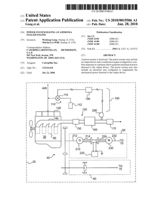
  • 1. US 20100019506A1 (19) United States 1mA0620.}58921. 0%NJ102S U:."m03NDb.b.UHPPon00 n001tac01lbHPn001tac01l0..My tnlm3t amPGm Publication Classi?cation (51) Int. Cl. (54) POWER SYSTEM HAVING AN AMMONIA FUELED ENGINE (2006.01) (2006.01) F023 63/04 F023 43/00 F02D 41/00 (75) Inventors: Weidong Gong, Dunlap, IL (US); Martin Leo Willi, Dunlap, IL (US) (2006.01) Correspondence Address: _ _ CATERPILLAR/FINNEGAN, HENDERSON, (52) US. Cl. 290/1 A, 123/1 A, 123/672 L.L.P. (57) ABSTRACT A poWer system is disclosed. The poWer system may include an output device and a combustion engine con?gured to com 901 New York Avenue, NW WASHINGTON, DC 20001-4413 (US) (73) Assignee: Caterpillar Inc. _ _ _ bust ammoma as a pr1mary fuel to generate mechanical poWer (21) App1_ NO; 12/219,418 directed to the output device. The poWer system may also include an electrical unit con?gured to supplement the mechanical poWer directed to the output device.(22) Filed: Jul. 22, 2008 200120 112 116 110A’ 130 AIR
  • 2. Patent Application Publication Jan. 28, 2010 Sheet 1 0f 2 US 2010/0019506 A1 F I I O 00 E 8| o O ‘r o °°°°° °°| :0: O//r. 20
  • 3.
  • 4. US 2010/0019506 A1 POWER SYSTEM HAVING AN AMMONIA FUELED ENGINE TECHNICAL FIELD [0001] The present disclosure is directed to a power system and, more particularly, to a poWer system having an ammonia fueled engine. BACKGROUND [0002] Increasing concerns on global Warming have given impetus to the search for Zero-carbon fuels for use in com bustion engines. Characteristics of ammonia fuel, such as Zero CO2 emission, relatively high energy density, Well-es tablished production infrastructure, and competitive cost, have made ammonia an attractive alternative fuel for com bustion engines. When ammonia is combusted, the combus tionproduces a ?ame With a relatively loW propagation speed. In other Words, the combustion rate of ammonia is loW. This loW combustion rate of ammonia causes combustion to be inconsistent under loW engine load and/or high engine speed operating conditions. Most existing combustion engines that use ammonia as engine fuel typically require a combustion promoter (i.e., a second fuel such as gasoline, hydrogen, diesel, etc.) for ignition, operation at loW engine loads and/or high engine speed. HoWever, the requirement forthe combus tion promoter fuel ?uctuates With varying engine loads and engine speed, Which can cause control issues. Furthermore, the use of dual fuels generally requires dual fuel storage systems, dual delivery systems, and dual injection systems, thus adding additional Weight, complexity, and cost to the engine system. To eliminate the use of combustion promoter fuel, combustion engines that burn ammonia alone as engine fuel have been explored. [0003] One such combustion engine that burns only ammo nia as a fuel is described in US. Pat. No. 3,455,282 (the ’282 patent) issued to T. J. Pearsall on Sep. 25, 1967. The ’282 patent describes a combustion engine having a substantially spherical combustion chamber for combusting ammonia alone as fuel. To ensure performance at loW load conditions, the combustion engine uses highly compressed ammonia With a compression ratio of the order of 12:1 to 16: 1. Due to the loW rate of ?ame propagation, performance of the dis closed ammonia-fueled combustion engine decreases at engine speeds above 3000 rpm. As such, an added fuel such as hydrogen is still needed to improve performance at speeds above 3000 rpm. [0004] Although the combustion engine ofthe ’282 patent may seem promising in eliminating the need for combustion promoter fuel, such a combustion engine may still have lim ited applicability. In particular, the engine ofthe ’282 patent may still perform poorly in applications Where engine speeds are high Without the use of a second fuel. [0005] The poWer system of the present disclosure is directed toWard improvements in the existing technology. SUMMARY [0006] One aspect ofthe present disclosure is directed to a poWer system. The poWer system may include an output device and a combustion engine con?gured to combust ammonia as a primary fuel to generate mechanical poWer directed to the output device. The poWer system may also include an electrical unit con?gured to supplement the mechanical poWer directed to the output device. Jan. 28, 2010 [0007] Another aspect ofthe present disclosure is directed to a method of operating a poWer system. The method may include combusting ammonia as a primary fuel to generate mechanical poWer directed to drive the poWer system. The method may also include electrically supplementing the mechanical poWer directed to drive the poWer system. BRIEF DESCRIPTION OF THE DRAWINGS [0008] FIG. 1 is a diagrammatic illustration of an exem plary disclosed machine; and [0009] FIG. 2 is a schematic illustration of an exemplary disclosed poWer system that may be used With the machine of FIG. 1. DETAILED DESCRIPTION [0010] FIG. 1 diagrammatically illustrates an exemplary machine 10. Machine 10 may be a mobile machine such as a vehicle, or a stationary machine such as a pump, a poWer generator, etc. For illustrative purposes, machine 10 is sche matically shoWn as a vehicle in FIG. 1. [0011] Machine 10 may include a poWer system 20 con?g ured to provide poWer to drive machine 10. PoWer system 20 may include a combustion engine 30 con?gured to combust ammonia as a primary fuel and produce mechanical poWer used to drive machine 10. For the purpose ofthis disclosure, a fuel may be regarded as a “primary” fuel if the fuel consti tutes, for example, at least 80% ofthe total fuel directed into and combusted by combustion engine 30. In some embodi ment, ammonia fuel may constitute 90%-95%, or even as high as 100% (ammonia being the only fuel) ofthe total fuel combusted by combustion engine 30. It is understood that the percentage used here may be based on mass, volume, or thermal energy of the fuel. The fuel directed into and com busted by combustion engine 30 may, in some situations, include additives, such as detergents, lubricants, ethanol, etc. [0012] Machine 10 may also include a drivetrain 40 coupled to and driven by combustion engine 30. Drivetrain 40 may include a transmission 60 con?gured to receive the mechanical poWer produced by combustion engine 30 and to transmit the mechanical poWer to an output device 70, and an electrical unit 50 con?gured to convert a portion of the mechanical poWerproducedby combustionengine 30 to elec trical poWer selectively used to drive output device 70 during particular operating conditions. Output device 70 may be con?gured to output the mechanical poWer to drive a load 80. In the embodiment shoWn in FIG. 1, load 80 may be one or more traction devices con?gured to propel machine 10, for example, Wheels. [0013] As shoWn in FIG. 2, combustion engine 30 may include one or more cylinders 90 at least partially de?ning one or more combustion chambers. Combustion engine 30 may also include a fuel supply system 110 con?gured to provide ammonia fuel to cylinders 90, and an exhaust system 120 con?gured to treat exhaust received from cylinders 90. [0014] Fuel supply system 110 may supply ammonia to cylinders 90 for combustion. Fuel supply system 110 may include an onboard supply 112 of ammonia, and a control device 116, for example a valve, con?gured to adjust an amount of ammonia supplied to combustion engine 30. Ammonia may be supplied directly to cylinders 90 or, in some embodiments, ?rst mixed With combustion air directed into an intake manifold 130 of combustion engine 30. It is con templated that, When a ?uid in addition to ammonia is
  • 5. US 2010/0019506 A1 directed into combustion engine 30, fuel supply system 110 may include additional onboard supply and/or delivery devices, if desired. [0015] Exhaust system 120 may include an exhaust mani fold 140 connected With cylinders 90. The exhaust produced by combustion engine 30 may be directed from cylinders 90 through exhaust manifold 140 to the atmosphere. Exhaust system 120 may also include one or more exhaust treatment devices in communication With exhaust manifold 140 to treat the exhaust prior to discharge. For example, exhaust system 120 may include a ?rst oxidation catalyst 150, a constituent reducing device 160, and a second oxidation catalyst 170. It is contemplated that exhaust system 120 may include additional or different exhaust treatment devices than shoWn in FIG. 2, if desired. [0016] First oxidation catalyst 150 may receive exhaust exiting combustion engine 30. The exhaust produced from combusting ammonia may contain NO,C (such as NO and N02). First oxidation catalyst 150 may oxidiZe NO to convert NO into N02, thereby, changing a ratio ofNOzNO2 Within the exhaust. In some embodiments, for doWnstream constituent reducing device 160 to perform optimally, the ratio of NOzNO2 should be about 1:1. It is contemplated that exhaust system 120 may also include a particulate ?lter (not shoWn) con?gured to reduce particulate matter in the exhaust. If included, the particulate ?lter may be located upstream or doWnstream of ?rst oxidation catalyst 150, or may be inte grated With ?rst oxidation catalyst 150 to form a single unit. [0017] Constituent reducing device 160 may be con?gured to reduce a constituent of the exhaust, and may be located doWnstream of ?rst oxidation catalyst 150. In one embodi ment, constituent reducing device 160 may include a selective catalytic reduction (SCR) device con?gured to reduce NO,C in the exhaust using a reducing agent, such as ammonia, urea, diesel fuel, etc. Since ammonia may be combusted as a pri mary engine fuel, it is possible that there is suf?cient unburned residual ammonia Within the exhaust to reduce NO,C Within the SCR device Without additional reductant being injected. Therefore, an injection device normally needed for injecting the reducing agent may be eliminated. In some embodiments, constituent reducing device 160 may be inte grated With ?rst oxidation catalyst 150 as a single component. [0018] Second oxidation catalyst 170 may be provided at a doWnstream end of exhaust system 120, for example, doWn stream of constituent reducing device 160. Second oxidation catalyst 170 may be con?gured to oxidiZe one or more con stituents of the exhaust after the exhaust has already been treated by other upstream devices, and before the exhaust is released to the atmosphere. In some embodiments, second oxidation catalyst 170 may be con?gured to oxidiZe excess ammonia remaining Within the exhaust. [0019] A control system 180 may be associated With exhaust system 120, to regulate operations thereof. Control system 180 may include a controller 190 and a sensor 200 in communication With controller 190. Sensor 200 may be con ?gured to measure an amount ofan exhaust constituent Within the exhaust, e.g., NO,C or residual ammonia fuel Within the exhaust. Based on signals from sensor 200, controller 190 may adjust control device 116 to change the amount of ammonia supplied to combustion engine 30, thereby control ling constituent emissions in the exhaust. [0020] Controller 190 may be a stand-alone controller or an existing engine control module, and may include a control algorithm for controlling various devices including sensor Jan. 28, 2010 200 and control device 116. It is contemplated that controller 190 may be associated With other devices or systems, such as electrical unit 50, if desired. [0021] Sensor 200 may be disposed at any suitable location Within exhaust system 120, for example, doWnstream ofcon stituent reducing device 160 and upstream of second oxida tion catalyst 170, or doWnstream ofsecond oxidation catalyst 170. In some embodiments, sensor 200 may include tWo separate sensors, a NO,C sensor con?gured to measure an amount of NO,C Within the exhaust, and an ammonia sensor con?gured to measure an amount of ammonia Within the exhaust. Sensor 200 may generate a signal indicative of an amount ofNO,C and/or ammonia Within the exhaust and may direct the signal to controller 190. [0022] Electrical unit 50 may be poWered by combustion engine 30, and may electrically supplement the mechanical poWer directed from electrical unit 50 to output device 70. Electrical unit 50 may include, among other things, a genera tor 210, a poWer storage 220, for example a battery, and an electric motor 230. Generator 210 may be drivingly coupled With combustion engine 30 through a ?rst mechanical link 212, and electrically connected With poWer storage 220 via a ?rst electrical line 214. PoWer storage 220 may be further connected With electric motor 230 via a second electric line 224. Electric motor 230 may be mechanically coupled With output device 70 through a second mechanical link 232. Although not shoWn, it is contemplated that electrical unit 50 may be connected With and regulated by controller 190, if desired. [0023] Transmission 60 may be any suitable (e.g., manual or automatic) transmission knoWn in the art. Transmission 60 may be mechanically coupled With combustion engine 30 to receive mechanical poWer generated by combustion engine 30 and to transmit the received mechanical poWer to output device 70 through a plurality ofgears, rotating shafts, hydrau lic circuits, etc. INDUSTRIAL APPLICABILITY [0024] The disclosed ammonia fueled combustion engine and electrical unit may be employed in poWer system appli cations Where loW CO2 and NO,C emissions, consistent per formance, and loW operating cost are desired. Speci?cally, by combusting ammonia as a primary fuel, extremely loW CO2 emission, or even Zero CO2 emission, may be achieved. NO,C emissions may also be reduced to a loW level by using unburned residual ammonia fuel as a NOx-reducing agent in an SCR device, Without requiring additional reductant dosing equipment. And, by electrically supplementing mechanical poWer directed to the poWer system, the operating range ofthe poWer system may be expanded to loW load and high speed situations. In addition, because the cost ofammonia as a fuel may relativelybe loW, substantial savings may be providedby the disclosed poWer system. [0025] Referring to FIG. 1, poWer system 20 may generate poWer to drive machine 10 using combustion engine 30 and electrical unit 50, independently and in combination. Mechanical poWer may be generated by combustion engine 30 from combustion ofammonia as a primary fuel andmay be directed to drive output device 70. Speci?cally, the generated mechanical poWer may be transmitted by transmission 60 from combustion engine 30 to output device 70, Which may further output the mechanical poWer to drive load 80 of machine 10.
  • 6. US 2010/0019506 A1 [0026] To help avoid inconsistent combustion due to the loW combustion rate of ammonia, the operating range of combustion engine 30 may be controllably limited. That is, combustion engine 30 may be limited to operate Within a predetermined engine load range, for example, 30% to 100% of a designed maximum engine load. When a poWer demand from poWer system 20 for driving output device 70 is outside of the predetermined engine load range, for example, loWer than 30% or higher than 100% of the designed maximum engine load, electrical unit 50 may be used to electrically supplement the mechanical poWer generated by combustion engine 30. For example, When the poWer demand of output device 70 is loWer than 30% ofthe designed maximum engine load, combustion engine 30 may still Work at 30% of the designed maximum engine load, and the excess poWermay be absorbed by electrical unit 50 and stored in poWer storage 220. Combustion engine 30 may be shut doWn and the demanded poWer may be provided by poWer storage 220 through electrical unit 50. [0027] In addition, the engine speed of combustion engine 30 may be limited to help ensure consistent performance of poWer system 20. For example, the engine speed may be limited to about 6000 rpm. When a desired operating engine speedexceeds thepredetermined engine speed ofcombustion engine 30, and/or When a poWer demand from poWer system 20 exceeds the mechanical poWer generated by combustion engine 30, electrical unit 50 may provide additional poWer to output device 70. Because the mechanical poWer generated by combustion engine 30 may be electrically supplemented by electrical unit 50 under various operation conditions, issues associated With utiliZing ammonia as a primary fuel may be avoided. [0028] Referring to FIG. 2, poWer system 20 may be driven using only the electrical poWerprovided by electrical unit 50. For example, Machine 10 may be operated in loW poWer conditions, for example, under stop-and-go driving condi tions in a city. The poWer demand from poWer system 20 in these conditions may be insuf?cient (e.g., loWer than the loWest engine load inthe predetermined engine loadrange) to maintain consistent operation ofcombustion engine 30, even With the assistance of electrical unit 50. In such conditions, electrical unit 50 alone may provide poWer to poWer system 20, and combustion engine 30 may be shut doWn. [0029] In some operating situations, the poWer demand from poWer system 20 may be too high for electrical unit 50 alone to provide poWer for the demand, but insuf?cient for combustion engine 30 alone to be operated consistently. In such conditions, combustion engine 30 may still be used to provide poWer to poWer system 20, and electrical unit 50 may be used to intentionally increase the engine load on combus tion engine 30 by converting a portion of the mechanical poWer of combustion engine 30 into electrical poWer. When poWer storage 220 reaches its full capacity, electrical unit 50 may be turned off, for example, by controller 190. In this manner, electrical unit 50 may help ensure combustion engine 30 is operated at a load condition that is high enough for stable, consistent, and ef?cient operation. [0030] In some operating situations, the poWer demand from poWer system 20 may be large enough for combustion engine 30 to be consistently and e?iciently operated Without assistance from electrical unit 50. That is, the load on com bustion engine 30 may be Within the predetermined engine load range. Under such conditions, combustion engine 30 alone may provide poWer to poWer system 20. Jan. 28, 2010 [0031] In some operating conditions, the poWer demand from poWer system 20 may exceed the mechanical poWer capacity of combustion engine 30. In such conditions, elec trical unit 50 may provide additional poWer to poWer system 20. Thus, combustion engine 30 and electrical unit 50 may simultaneously provide poWerto poWer system 20 for driving machine 10. [0032] Controller 190 may control the air/fuel ratio ofcom bustion engine 30 by adjusting, for example, the amount of ammonia fuel directed through control device 116. An amount ofammonia fuel in excess ofa stoichiometric amount (i.e., equivalence ratio greater than 1.0) may be supplied to combustion engine 30, such that residual ammonia fuel is present Withinthe exhaust. The residual ammonia fuel may be used as a reductant for reducing NO,C Within constituent reducing device 160. At constituent reducing device 160, the residual ammonia fuel may react With NO,C to convert NO,C to nitrogen andWater. Controller 190 may analyZe the amount of NOX, the amount of ammonia, or both measured by sensor 200, and responsively adjust the amount of ammonia fuel supplied to combustion engine 30. With such a feedback system, NO,C and ammonia emissions to the atmosphere may be controlled to be beloW a predetermined level. [0033] It Will be apparent to those skilled in the art that various modi?cations and variations can be made to the poWer system of the present disclosure Without departing from the scope ofthe disclosure. Other embodiments Will be apparent to those skilled in the art from consideration of the speci?cation and practice of the poWer system disclosed herein. It is intended that the speci?cation and examples be considered as exemplary only, With a true scope of the dis closure being indicated by the folloWing claims and their equivalents. What is claimed is: 1. A poWer system, comprising: an output device; a combustion engine con?gured to combust ammonia as a primary fuel to generate mechanical poWer directed to the output device; and an electrical unit con?gured to supplement the mechanical poWer directed to the output device. 2. The poWer system of claim 1, Wherein the combustion engine is con?gured to combust ammonia as the only fuel to generate the mechanical poWer directed to the output device. 3. The poWer system ofclaim 1, Wherein the electrical unit is con?gured to supplement the mechanical poWer When a poWer demand from the poWer system is outside of a prede termined engine load range. 4. The poWer system ofclaim 1, Wherein the electrical unit is con?gured to supplement the mechanical poWer When a desired operating engine speed of the combustion engine exceeds a predetermined engine speed. 5. The poWer system ofclaim 1, Wherein the electrical unit includes at least one of a poWer storage, a generator, or an electric motor. 6. The poWer system of claim 1, further including: a sensor con?gured to measure at least one of an amount of NO,C or an amount of residual ammonia fuel Within exhaust produced by the combustion engine; and a controller con?gured to adjust an amount of ammonia supplied to the combustion engine as the primary fuel based on at least one ofthe measured amount ofNO,C or residual ammonia fuel.
  • 7. US 2010/0019506 A1 7. The power system of claim 1, further including a con stituent reducing device con?gured to use residual ammonia fuel Within exhaust produced by the combustion engine to reduce a constituent of the exhaust. 8. The poWer system of claim 7, Wherein the constituent reducing device includes a selective catalytic reduction device. 9. The poWer system ofclaim 7, Wherein the constituent of the exhaust is NOX. 10. The poWer system of claim 1, Wherein the electrical unit is con?gured to increase an engine load of the combus tion engine When a poWer demand from the poWer system is insuf?cient to maintain consistent operation of the combus tion engine. 11. A method of operating a poWer system, comprising: combusting ammonia as a primary fuel to generate mechanical poWer directed to drive the poWer system; and electrically supplementing the mechanical poWer directed to drive the poWer system. 12. The method of claim 11, further including: converting a portion ofthe mechanical poWer into electri cal poWer; and directing the electrical poWer to supplement the mechani cal poWer directed to drive the poWer system. 13. The method of claim 11, further including: supplying ammonia fuel in excess of a stoichiometric amount into the poWer system; and reducing a constituent ofthe exhaust using residual ammo nia fuel Within the exhaust. 14. The method of claim 11, further including: measuring at least one ofan amount ofan exhaust constitu ent or an amount of residual ammonia fuel Within the exhaust; and adjusting an amount ofammonia fuel supplied to the poWer system based on the at least one ofthe measured amount Jan. 28, 2010 ofthe exhaust constituent or the measured amount ofthe residual ammonia fuel Within the exhaust. 15. The method of claim 11, Wherein electrically supple menting the mechanical poWer includes electrically supple menting the mechanical poWer When a poWer demand from the poWer system is outside of a predetermined engine load range. 16. The method of claim 11, Wherein electrically supple menting the mechanical poWer further includes electrically supplementing the mechanical poWer When a desired operat ing engine speed exceeds a predetermined engine speed. 17. The method ofclaim 11, Wherein combusting ammonia as the primary fuel includes combusting ammonia as the only fuel. 18. The method ofclaim 11, further including increasing an engine load by converting mechanical poWer generated from combusting ammonia into electrical poWer When a poWer demand from the poWer system is insuf?cient to sustain con sistent combustion of the ammonia. 19. A machine, comprising: a traction device con?gured to propel the machine; an onboard supply of ammonia fuel; a combustion engine con?gured to combust the ammonia fuel as a primary fuel and generate mechanical poWer directed to the traction device; an electrical unit poWered by the combustion engine to electrically supplement the mechanical poWer directed to the traction device; and a constituent reducing device con?gured to use residual ammonia fuel from exhaust exiting the combustion engine to reduce a constituent ofthe exhaust. 20. The machine ofclaim 19, Wherein the electrical unit is con?gured to supplement the mechanical poWer When a poWer demand from a poWer system is outside of a predeter mined engine load range, or When a desired operating engine speed exceeds a predetermined engine speed. * * * * *