Portable Earthing, Earth End Clamps, Line End Clamps - Transmission Lines
•
0 likes•672 views

Portable Earthing, Earth End Clamps, Line End Clamps - Transmission Lines
Recommended

Recommended
More Related Content
What's hot
What's hot (15)
Similar to Portable Earthing, Earth End Clamps, Line End Clamps - Transmission Lines
Similar to Portable Earthing, Earth End Clamps, Line End Clamps - Transmission Lines (20)
More from Thorne & Derrick International
More from Thorne & Derrick International (20)
Recently uploaded
Recently uploaded (20)
Portable Earthing, Earth End Clamps, Line End Clamps - Transmission Lines
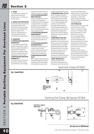
- 1. SECTION 2 Portable Earthing Equipment For Overhead Lines P & B WE I R E A R T H I N G E Q U I PME N T C ATA L O G U E 2 0 0 0 10 All sizes are in Millimetres 1. Scope The complete range, and details of this equipment will be identified and illustrated in Figs. 1 to 14 inclusive, at the end of section 2. 2. Design and Construction All clamps are designed with an ultimate strength well in excess of normal working loads, and all designs are type tested at normal loading before being approved for production. The construction of all equipment is of a robust nature and will withstand a reasonable amount of rough handling. 3. Equipment 3.1 Earth End Clamp Code CE10/A1 (Standard) Fig.1 For direct application by hand to tower steelwork. The large thumb screw of this device has a captive hardened steel tip which penetrates through painted, weathered or non conductive surfaces and indents into steel work ensuring a strong efficient connection to earth. 3.2 Earth End Clamp Code CE18/A (Bridging) Fig. 2 For earthing line conductor over tension set insulators to tower arm coupling during maintenance, bolts to coupling through clearance hole for arcing horn bolt which is removed prior to earthing. 3.3 Line End Clamp Code CE52/A (Normal Type) Fig. 3 Intended to be applied only by means of an operating socket attached to an insulated operating pole in either upward or downward direction. Spring loaded jaws enable clamp to be slipped easily over the line conductor and retains clamp in position whilst operating screw is being tightened/loosened. 3.4 Line End Clamp Code CE13/A (Angled Type) Fig. 4 As above but designed to be applied in near horizontal position from tower cross arm over tension set insulators to line conductor. 3.5 Line End Clamp Code CE23/A (Running Earth) Fig. 5 Designed specifically for earthing line conductors during "Stringing" operations. Enables cable to run freely between contact roller faces whilst providing a positive contact to earth. 3.6 Operating Socket Code OL1 Fig.10 Made in light alloy material with internal spring loaded plunger which maintains grip pressure on the inserted operating screw, holding both screw and clamp rigid whilst being directed into position. 3.7 Operating Poles Figs. 12,13,14 Made in strong glass fibre material in accordance with C.E.G.B. Specification 43921. Supplied as single 2.4m (8ft) section complete with operating socket or as 2.4m (8ft) heavy duty telescopic extending to 4.8m (16ft) with two intermediate positive stop positions. Lengths of the telescopic poles can be increased further by use of a single 1.8m (6ft) extension pole, supplied when specified. Carrying slings for telescopic and extension poles can be supplied as optional extra. 3.8 CE60 ‘Sparrow’ Plate Fig 8 Multiple earth tower bonding plate designed for control of induced currents. Manufactured from aluminium alloy and provided with location for up to twelve portable drain earths fitted with PB50F ferrule type terminations. Also provided with bolted connections for up to four interconnecting earth leads. Six thumbscrews with (replaceable) hardened tips for effective bonding to the tower structure are also incorporated. 3.9 CE61 ‘DEAS’ Bar Fig .9 Developed by the National Grid Company as an earthing bar for use in the arcing horn bolt hole of the earth side insulator string arrangement, when lowering off tension set insulators. Made from aluminium alloy, this equipment may be used in conjunction with CE52/A, CE31/A Line End Clamps, CE10/A1, CE10/A Earth End Clamps and CE18/A Bridging Earth. 3.10 Earthing Leads Flexible conductors are of commercially pure aluminium wires in the H68 condition. The conductor is wrapped with a layer of P.T.P. tape and covered with an extruded clear P.V.C sheath. Earth End to Line End Clamp interconnecting leads are 50mm2 nominal sectional area. These are terminated by PB50F type ferrule terminations. Flexible clear P.V.C stress relieving sleeves are fitted to prevent excessive wear about the compression joints, which can occur due to wind oscillation in service. Earth leads are 120mm2 nominal sectional area are terminated by PB120 palm type terminations. Flexible clear P.V.C stress relieving sleeves are fitted to prevent excessive wear about the compression joints. Section 2 Ear th End Clamp CE10/A1 Ear thing End Clamp (Br idging) CE18/A Fig. 1 Code CE10/A1 Fig. 2 Code CE18/A 32 60 144 6.35 PB50F Ferrule or Bared 50sq.mm Aluflex 11 max 51 92 83 54 312/0.45mm (50mm2) Earthing Lead 12.4 Dia THORNE AND DERRICK UK – LEAK DETECTION TEL: 0044 (0)191 490 1547 FAX: 0044 (0)191 477 5371 TEL: 0044 (0)117 977 4647 FAX: 0044 (0)117 477 5582 WWW.HEATTRACING.CO.UK WWW.THORNEANDDERRICK.CO.UK e-mail: northernsales@thorneandderrick.co.uk