
Recommended
Recommended
More Related Content
What's hot
What's hot (20)
Similar to Liebherr rmg-rail-mounted-gantry-cranes-technical-description
Similar to Liebherr rmg-rail-mounted-gantry-cranes-technical-description (20)
Recently uploaded
Recently uploaded (20)
Liebherr rmg-rail-mounted-gantry-cranes-technical-description
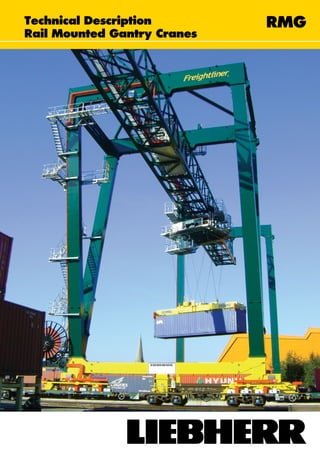
- 1. Technical Description Rail Mounted Gantry Cranes RMG
- 2. 2 Rail Mounted Gantry Cranes (RMG) Technical Data Typical RMG Model Range* A: Gantry span 22 - 70 m B: Lifting Height From 9.2 m for 1 over 2 Up to 26.9 for 1 over 8 C: Cantilever 0 - 20 m D: Cantilever 0 - 20 m E: Travel wheel guage 16.5 m - 18.2 m F: Buffer to buffer 23.2 m - 25.5 m G: Wheel spacing 1 m - 2 m dependant on wheel loads Wheels per corner 6 - wide leg 4 - narrow leg SWL 40.6 - 50 t single | 50 - 65 t twin *Other features and dimensions also available Typical Design Parameters* Classification according to F.E.M. U7-Q2-A7 (Single lift) In service wind speed 72 km/h (20 m/s) Out of service wind speed 151.2 km/h (42 m/s) Ambient temperature range -45°C to + 45°C RMG Model Designation S190 L (MT) / (RT) Rotating machinery trolley (optional) Machinery trolley Lattice structure for main beam Hoist motor size Advantages of RMG for Yard Stacking • Suitable for both port and rail terminals. • Suitable for various yard space conditions. • Increased yard capacity with wider and higher stack possibilities. • Reduction in emissions and noise. • Minimal maintenance. • Electric supply for energy efficiency and reduced running costs. Working Speeds** Hoisting with no load 56 m/min Hoisting with rated load 28 m/min Trolley travel (with and without load) 70 m/min Gantry travel without load 130 m/min Slewing ± 190° (optional) 1.2 RPM
- 3. Rail Mounted Gantry Cranes (RMG) 3 Motors and Speed Control System Motors / Suppliers • All drives are sized for maximum torque and power requirements, guaranteeing extended lifetime. • All major components are sourced from reputable european manufacturers. • The control system used has been specifically developed for container cranes by Liebherr, which has resulted in a flexible, robust construction with exceptional reliability. • The “plug-in” modular construction of the electronic equipment is designed to maximise crane availability and minimise the necessity for highly skilled electronic personnel. Advantages by Design • Minimal spreader positioning times. • No-sway in hoist, trolley and travel directions. • Anti-skew. • No additional ropes or devices necessary. • No head block - Reduced rope load and tare weight. Liebherr Anti-Sway System (Eight Rope Reeving) • Lower energy consumption. • All electric spreader - Less maintenance. • Significant increase in productivity when compared with alternative designs. Speed Control System
- 4. Liebherr Container Cranes Ltd. Fossa, Killarney, Co. Kerry, Ireland Tel.: +353 64 66 70 200 sales.lcc@liebherr.com facebook.com/liebherrmaritime www.liebherr.com Liebherr Rail Mounted Gantry Crane RMG—06/2014—Subject to change without notice. Description • Worldwide Liebherr service network. • Extensive training (in-house and on-site). • Purpose built state-of-the-art design and production facilities located in Ireland since 1958. • Highly skilled and experienced employees with expertise in- house for after sales service. • Responsibility with Liebherr, eliminating interface and compatibility problems (i.e. structural, mechanical and electrical design, production, commissioning and service). • Liebherr reeving system: Sway prevention, not sway correction. • Regeneration during lowering of load and drive deceleration, results in overall reduction in power consumption. • Electric (gantry align) steering. • Rigid robust structure - Optimum for automation. Optional DGPS auto steering and container positioning. • Direct gearbox driven travel systems. • Separate drives for hoist, travel and trolley, with no need for side shift on the spreader. Allows superior fine positioning with simultaneous motion. Options • Rotating machinery trolley. • Interface with TOS (terminal operating system). • Trim and skew spreader positioning. • Energy chain / festoon system. • Non-contact anti-collision system. • Automation of RMG and container tracking. • Container positioning system. • Remote operation option. • Fault data between crane and office by RF link / Fibre optic with optional link to the Liebherr factory. • Liebherr designed and built. • Windows OS with CoDeSys logic control system. • Status of switchgear and external electrical components. • Stores up to 20,000 faults. • User-friendly interface with easy to use colourful screens. • Independence of crane logic system, therefore does not interfere with crane control in the event of self failure. • Includes trending and tables for production data and drive data. Diagnostic and Managment System Summary of Main System Features • General Control Overview. • “Crane ON” status. • Individual Drive ON screens (one for each drive). • Detailed drive data (motor current, voltage, speed). • Wind speed and history. • Spreader status. • Fault stack. • Load statistics. • Maintenance.