SlideShare a Scribd company logo
1 of 10
Download to read offline
The International Journal Of Engineering And Science (IJES) 
|| Volume || 3 || Issue || 8 || Pages || 67-76 || 2014 || 
ISSN (e): 2319 – 1813 ISSN (p): 2319 – 1805 
www.theijes.com The IJES Page 67 
Design of a Digital Baseband Processor for UWB Transceiver on RFID Tag 1, G.Sri Naga Chaitanya.B.Tech, 2, R.S.Harishraghav.B.Tech 1, 2, Sree Vidyanikethan Engg. College 
-------------------------------------------------------------ABSTRACT-------------------------------------------------------- 
This paper shows a novel digital baseband processor designed for UWB Transceiver on RFID tag which reduces the complexity, area and power consumption of the baseband processor. Furthermore, several strategies of reducing the power has explored during the design, so the final power consumption of the baseband processor basically fulfils the ultra low power requirements of the UWB Transceiver. 
Key words: - UWB Transceiver, RFID tag, digital baseband processor. --------------------------------------------------------------------------------------------------------------------------------------- 
Date of Submission: 30 July 2014 Date of Publication: 15 August 2014 --------------------------------------------------------------------------------------------------------------------------------------- 
I. INTRODUCTION 
RFID (Radio-Frequency Identification) technology has drawn a swirl of attention in the past few years as it helps identify objects and people in a fast, accurate and inexpensive way, Today, RFID is used in enterprise supply chain management to improve the efficiency of inventory tracking and management. However, growth and adoption in the enterprise supply chain market is limited because current commercial technology does not link the indoor tracking to the overall end-to-end supply chain visibility. Coupled with fair cost-sharing mechanisms, rational motives and justified returns from RFID technology investments are the key ingredients to achieve long-term and sustainable RFID technology adoption. Figure 1.1: Overview of the most important auto-ID procedures Optical character recognition (OCR) was first used in the 1960s. Special fonts were developed for this application that stylized characters so that they could be read both in the normal way by people and automatically by machines. The most important advantage of OCR systems is the high density of information and the possibility of reading data visually in an emergency. Biometrics is defined as the science of counting and (body) measurement procedures involving living beings. In the context of identification systems, biometry is the general term for all procedures that identify people by comparing unmistakable and individual physical characteristics. In practice, these are fingerprinting and hand printing procedures, voice identification and, less commonly, retina (or iris) identification. A smart card is an electronic data storage system, possibly with additional computing capacity (microprocessor card), which is perfect for convenience..
Design of a Digital Baseband Processor for UWB Transceiver on RFID Tag 
www.theijes.com The IJES Page 68 
Table 1.1: Comparison of different auto-ID systems. 
1.1 APPLICATIONS 
RFID is a versatile technology, capable of being used by businesses and the government. Mandates for supply chains, while raising the profile of RFID in business, have overshadowed how extensively and successfully RFID is used in other contexts. In the early part of the 21st century, RFID is growing. The list of RFID users is a long one’s 
• Supply Chains, Including Wholesale and Retail Inventory and Materials Management 
 Item-level Tagging of Consumer Goods on Retail Shelves 
 Toll Payment Systems 
 Smart Cards. 
 Contactless Payment Systems at the Retail Point of Sale (POS) 
 Logistics 
 Asset Tracking 
 Automobile Keyless Start Systems 
 Sports 
Pharmaceutical Anti-drug Counterfeiting 
II. RFID SYSTEM AND ITS COMPONENTS 
RFID systems are composed of three key components. 
• The RFID tag, or transponder, carries object identifying data. 
• The RFID tag reader, or transceiver, reads and writes tag data. 
• The back-end database stores records associated with tag contents. 
Figure 2.1: RFID system components A key classification of RFID tags is the source of power. Tags come in three general varieties: active, semi-passive and passive. Active tags contain an on-board power source, such as a battery, as well as the ability to initiate their own communications; possibly with other tags. Semi-passive tags have a battery, but may only respond to incoming transmissions. Passive tags have no internal power source and receive all power from the reader. Table 2.1 given below gives a brief idea of the different types of tags, its power source, transmitter and its maximum operating range. Figure 2.2 is the appearance or the display of the available passive, semi passive and active tags Table 2.1: Active, Semi-Passive and Passive tags 
RF circuit & analog circuit 
Baseband processor 
EEPROM 
READER
Design of a Digital Baseband Processor for UWB Transceiver on RFID Tag 
www.theijes.com The IJES Page 69 
Figure 2.2: Passive tag, Semi passive tag, Active tag 
2.1 OPERATING PRINCIPLE OF RFID SYSTEM 
An Interrogator receives information from a Tag by transmitting an un-modulated RF carrier and 
listening for a backscattered reply. Tags communicate information by backscatter-modulating the amplitude 
and/or phase of the RF carrier. The encoding format, selected in response to Interrogator commands, is either 
FM0 or Miller modulated sub-carrier. The communications link between Interrogators and Tags is half-duplex, 
meaning that Tags shall not be required to demodulate Interrogator commands while backscattering. A Tag shall 
not respond using full-duplex communications to a mandatory or optional command. RFID tag chip consists of a 
power reception system, an RF analog module, an EEPROM and a baseband-processor, shown in figure.2.3. 
The figure 2.4 shown above is the block diagram of a UHF RFID tag system. The baseband-processor is one of 
the major and most important parts of the tag chip, since it not only implements the “slotted aloha” random anti-collision 
algorithm and authorization scheme, but also executes read/write operation of EEPROM. 
Figure 2.3: Architecture of the RFID tag 
Figure 2.4: Block diagram of an RFID tag system 
2.2 HARDWARE MODELLING & IMPLEMENTATIONOFDIGITAL BASEBAND PROCESSOR 
Figure 2.5: Proposed block diagram of a baseband processor 
Figure 2.5 is the proposed block diagram of the Baseband processor. The baseband processor is the 
back-end part of the RFID system. The front-end part of the system comprises of a reader and the data 
communication between the processor and the reader takes place in half-duplex mode. The data flow between 
the sub modules is in parallel form synchronized with respect to clock. This can improve the efficiency of the 
Baseband processor significantly.
Design of a Digital Baseband Processor for UWB Transceiver on RFID Tag 
www.theijes.com The IJES Page 70 
III. INTRODUCTIONS TO VERILOG HDL 
3.1 INTRODUCTION TO VERILOG LANGUAGE There is no attempt in this handout to describe the complete Verilog language. It describes only the portions of the language needed to allow students to explore the architectural aspects of computers. In fact, this handout covers only a small fraction of the language. For the complete description of the Verilog HDL, consult the references at the end of the handout. 
3.2 A FIRST VERILOG PROGRAM module simple; // Simple Register Transfer Level (RTL) example to demo Verilog. // Register A is incremented by one. Then first four bits of B is // set to "not" of the last four bits of A. C is the "and" // reduction of the last two bits of A. //declare registers and flip-flops reg [0:7] A, B; reg C; // The two "initial"s and "always" will run concurrently initial begin: stop at // Will stop the execution after 20 simulation units. #20; $stop; end // These statements done at simulation time 0 (since no #k) initial begin: Init // Initialize register A. Other registers have values of "x" A = 0; // Display a header $display ("Time A B C"); // Prints the values anytime a value of A, B or C changes $monitor (“%0d %b %b %b", $time, A, B, C); end //main process will loop until simulation is over always begin: main process // #1 means do after one unit of simulation time #1 A = A + 1; #1 B[0:3] = ~A[4:7]; // ~ is bitwise "not" operator #1 C = &A[6:7]; // bitwise "and" reduction of last 2 bits of A end end module In module simple, we declared A and B as 8-bit registers and C a 1-bit register or flip-flop. Inside of the module, the one "always" and two "initial" constructs describe three threads of control, i.e., they run at the same time or concurrently. Within the initial construct, statements are executed sequentially much like in C or other traditional imperative programming languages. The always construct is the same as the initial construct except that it loops forever as long as the simulation runs. Below is the output of the VeriWell Simulator: (See Section 3 on how to use the VeriWell simulator.) Time A B C 0 00000000 xxxxxxxx x 1 00000001 xxxxxxxx x 2 00000001 1110xxxx x 3 00000001 1110xxxx 0 4 00000010 1110xxxx 0 5 00000010 1101xxxx 0 7 00000011 1101xxxx 0 8 00000011 1100xxxx 0 9 00000011 1100xxxx 1
Design of a Digital Baseband Processor for UWB Transceiver on RFID Tag 
www.theijes.com The IJES Page 71 
10 00000100 1100xxxx 1 11 00000100 1011xxxx 1 12 00000100 1011xxxx 0 13 00000101 1011xxxx 0 14 00000101 1010xxxx 0 16 00000110 1010xxxx 0 17 00000110 1001xxxx 0 19 00000111 1001xxxx 0 Stop at simulation time 20 
3.3 LEXICAL CONVENTIONS The lexical conventions are close to the programming language C++. Comments are designated by // to the end of a line or by /* to */ across several lines. Keywords, e. g., module, are reserved and in all lower case letters. The language is case sensitive, meaning upper and lower case letters are different. Spaces are important in that they delimit tokens in the language. Numbers are specified in the traditional form of a series of digits with or without a sign but also in the following form: <size><base format><number> Where <size> contains decimal digits that specify the size of the constant in the number of bits. The <size> is optional. The <base format> is the single character ' followed by one of the following characters b, d, o and h, which stand for binary, decimal, octal and hex, respectively. The <number> part contains digits which are legal for the <base format>. Some examples: 549 // decimal number 'h 8FF // hex number 'o765 // octal number 4'b11 // 4-bit binary number 0011 3'b10x // 3-bit binary number with least // significant bit unknown 5'd3 // 5-bit decimal number -4'b11 // 4-bit two's complement of 0011 or 1101 The <number> part may not contain a sign. Any sign must go on the front. A string is a sequence of characters enclosed in double quotes. "this is a string" Operators are one, two or three characters and are used in expressions. An identifier is specified by a letter or underscore followed by zero or more letters, digits, dollar signs and underscores. Identifiers can be up to 1024 characters. 3.4 CONTROL CONSTRUCTS 
Verilog HDL has a rich collection of control statements which can used in the procedural sections of code, i. e., within an initial or always block. Most of them will be familiar to the programmer of traditional programming languages like C. The main difference is instead of C's { } brackets, Verilog HDL uses begin and end. In Verilog, the { } brackets are used for concatenation of bit strings. Since most users are familiar with C, the following subsections typically show only an example of each construct. 3.4.1 Selection - if and case Statements The if statement is easy to use. if (A == 4) begin B = 2; end else begin B = 4; End Unlike the case statement in C, the first <value> that matches the value of the <expression> is selected and the associated statement is executed then control is transferred to after the endcase, i. e., no break statements are needed as in C.
Design of a Digital Baseband Processor for UWB Transceiver on RFID Tag 
www.theijes.com The IJES Page 72 
case (<expression>) <value1>: <statement> <value2>: <statement> default: <statement> endcase The following example checks a 1-bit signal for its value. case (sig) 1'bz: $display("Signal is floating"); 1'bx: $display("Signal is unknown"); default: $display("Signal is %b", sig); endcase 
3.4.2 Repetition - for, while and repeat Statements The for statement is very close to C's for statement except that the ++ and -- operators do not exist in Verilog. Therefore, we need to use i = i + 1. for(i = 0; i< 10; i = i + 1) begin $display("i= %0d", i); end The while statement acts in the normal fashion. i = 0; while(i< 10) begin $display("i= %0d", i); i = i + 1; end The repeat statement repeats the following block a fixed number of times, in this example, five times. repeat (5) begin $display("i= %0d", i); i = i + 1; end 
3.5 OTHER STATEMENTS 
3.5.1 Parameter Statement The parameter statement allows the designer to give a constant a name. Typical uses are to specify width of registers and delays. For example, the following allows the designer to parameterized the declarations of a model parameterbyte_size = 8; reg [byte_size - 1:0] A, B; 
3.5.2 Continuous Assignment Continuous assignments drive wire variables and are evaluated and updated whenever an input operand changes value. The following ands the values on the wires in1 and in2 and drives the wire out. The keyword assign is used to distinguish the continuous assignment from the procedural assignment. See Section 2.1 for more discussion on continuous assignment. Assignout = ~(in1 & in2); 
3.5.3 Blocking and Non-blocking Procedural Assignments The Verilog language has two forms of the procedural assignment statement: blocking and non- blocking. The two are distinguished by the = and <= assignment operators. The blocking assignment statement (= operator) acts much like in traditional programming languages. The whole statement is done before control passes on to the next statement. The non-blocking (<= operator) evaluates all the right-hand sides for the current time unit and assigns the left-hand sides at the end of the time unit. For example, the following Verilog program // testing blocking and non-blocking assignment module blocking;
Design of a Digital Baseband Processor for UWB Transceiver on RFID Tag 
www.theijes.com The IJES Page 73 
reg [0:7] A, B; initial begin: init1 A = 3; #1 A = A + 1; // blocking procedural assignment B = A + 1; $display("Blocking:A= %b B= %b", A, B ); A = 3; #1 A <= A + 1; // non-blocking procedural assignment B <= A + 1; #1 $display("Non-blocking: A= %b B= %b", A, B ); end end module produces the following output: Blocking: A= 00000100 B= 00000101 Non-blocking: A= 00000100 B= 00000100 The effect is for all the non-blocking assignments to use the old values of the variables at the beginning of the current time unit and to assign the registers new values at the end of the current time unit. This reflects how register transfers occur in some hardware systems. 
3.6 TASKS AND FUNCTION: Tasks are like procedures in other programming languages, e. g., tasks may have zero or more arguments and do not return a value. Functions act like function subprograms in other languages. Except: 1. A Verilog function must execute during one simulation time unit. That is, no time controlling statements, i. e., no delay control (#), no event control (@) or wait statements, allowed. A task may contain time controlled statements. 2. A Verilog function can not invoke (call, enable) a task; whereas a task may call other tasks and functions. The definition of a task is the following: task<task name>; // Notice: no parameter list or ()s <argument ports> <declarations> <statements> End task An invocation of a task is of the following form: <name of task> (<port list>); where<port list> is a list of expressions which correspond by position to the <argument ports> of the definition. Port arguments in the definition may be input, inout or output. Since the <argument ports> in the task definition look like declarations, the programmer must be careful in adding declares at the beginning of a task. // Testing tasks and functions // Dan Hyde, Aug 28, 1995 module tasks; task add; // task definition input a, b; // two input argument ports output c; // one output argument port reg R; // register declaration begin R = 1; if (a == b) c = 1 & R; else c = 0; end end task
Design of a Digital Baseband Processor for UWB Transceiver on RFID Tag 
www.theijes.com The IJES Page 74 
initial begin: init1 reg p; add(1, 0, p); // invocation of task with 3 arguments $display("p= %b", p); end end module input and inout parameters are passed by value to the task and output and inoutparameters are passed back to invocation by value on return. Call by reference is not available. 
3.7 TIMING CONTROL The Verilog language provides two types of explicit timing control over when simulation time procedural statements are to occur. The first type is a delay control in which an expression specifies the time duration between initially encountering the statement and when the statement actually executes. The second type of timing control is the event expression, which allows statement execution. The third subsection describes the wait statement which waits for a specific variable to change. Verilog is a discrete event time simulator, i. e., events are scheduled for discrete times and placed on an ordered-by-time wait queue. If there is no timing control, simulation time does not advance. Simulated time can only progress by one of the following: 1. gate or wire delay, if specified. 2. a delay control, introduced by the # symbol. 3. an event control, introduced by the @ symbol. 4. thewait statement. 
The order of execution of events in the same clock time may not be predictable. 
3.7.1 DELAY CONTROL A delay control expression specifies the time duration between initially encountering the statement and when the statement actually executes. For example: #10 A = A + 1; specifies to delay 10 time units before executing the procedural assignment statement. The # may be followed by an expression with variables. 3.7.2 EVENTS The execution of a procedural statement can be triggered with a value change on a wire or register, or the occurrence of a named event. Some examples: @r begin // controlled by any value change in A = B&C; // the register r end @(posedge clock2) A = B&C; // controlled by positive edge of clock2 @(negedge clock3) A = B&C; // controlled by negative edge of clock3 forever @(negedge clock) // controlled by negative edge begin A = B&C; end In the forms using posedge and negedge, they must be followed by a 1-bit expression, typically clock. A negedge is detected on the transition from 1 to 0 (or unknown). A posedge is detected on the transition from 0 to 1 (or unknown). Verilog also provides features to name an event and then to trigger the occurrence of that event. We must first declare the event: event event6; To trigger the event, we use the ->symbol : -> event6; To control a block of code, we use the @ symbol as shown: @(event6) begin <some procedural code> end 
We assume that the event occurs in one thread of control, i. e., concurrently, and the controlled code is in another thread. Several events may to or-ed inside the parentheses.
Design of a Digital Baseband Processor for UWB Transceiver on RFID Tag 
www.theijes.com The IJES Page 75 
3.7.3 WAIT STATEMENT The wait statement allows a procedural statement or a block to be delayed until a condition wait (A == 3) begin A = B&C; end The difference between the behavior of a wait statement and an event is that the wait statement is level sensitive whereas @(posedge clock); is triggered by a signal transition or is edge sensitive. 
3.7.4 FORK AND JOIN STATEMENTS By using the fork and join construct, Verilog allows more than one thread of control inside an initial or always construct. For example, to have three threads of control, you fork the thread into three and merge the three into one with a join as shown: fork: three //split thread into three; one for each begin-end begin // code for thread 1 end begin // code for thread 2 end begin // code for thread 3 end join // merge the three threads to one Each statement between the fork and join, in this case, the three begin-end blocks, is executed concurrently. After all the threads complete, the next statement after the join is executed. You must be careful that there is no interference between the different threads. For example, you can't change a register in two different threads during the same clock period. 
IV. 4. RESULT ANALYSIS 
The Verilog HDL code is written for both reference design 
• According to [1] given in figure 4.3, the controller in the architecture of the Baseband processor controls the data flow to the other sub modules. It sends control signals to control the status of all the sub modules. 
• But the modified design given in fig 4.7 incorporates a controller which controls not only the data flow to the sub modules but also controls the clock of each sub module. This reduces the power significantly. 
Figure4.1: Simulation result of the reference design obtained in xilinx tool 
Figure4.2: Simulation result of the modified design obtained in xilinx tool
Design of a Digital Baseband Processor for UWB Transceiver on RFID Tag 
www.theijes.com The IJES Page 76 
Figure 4.1 and figure 4.2 shown above are the simulation result of the reference design and the simulation result of the modified design obtained in Xilinx tool respectively. The design was simulated and synthesized using Xilinx tool. The selected device was Spartan 3E. The Clock of100 MHz was provided. Reset signal is active high. The input bits are 88 bits serial and the output obtained is 88 bits serial which is amplitude modulated. The internal operation is carried on parallel. One of the given test cases is 11001111000000010000000100000001000000010000000100000001000000010000000 1111111111111111 Expected output is: 011001111000000010000000100000001000000010000000100000001000000010000000101111100010110 The power analysis for both the reference design and modified design were carried out. The dynamic power obtained for both the designs are given in the Table 4.3 below. 
Table 5.1: Dynamic power obtained from xilinx tool 
CONCLUSION 
In this paper, a novel digital baseband processor designed for UWB Transceiver on RFID tag is presented. Due to the security feature and other advantages of UWB, no complicated coding and cryptography is needed. This also reduces the complexity, area and power consumption of the baseband processor. Furthermore, several strategies of reducing the power has explored during the design, so the final power consumption of the baseband processor basically fulfills the ultra low power requirements of the UWB Transceiver. Future works include integrating the baseband processor into the UWB Transceiver to test the whole system and researching for more strategies to reduce the power consumption of the baseband processor if possible. REFERENCES 
[1]. YuechaoNiu, Majid BaghaeiNejad, HannuTenhunen and Li-Rong Zheng, “Design of a Digital Baseband Processor for UWB Tranceiver on RFID Tag”, IEEE Conference on Advanced Information Networking and Applications Workshop proceedings, vol. 2, pp. 358-361, May 2007 
[2]. Adam S.W. Man, Edward S. Zhang, H.T. Chan, Vincent K.N. Lau, C.Y. Tsui and Howard C. Luong,“Design and Implementation of a Low-power Baseband-system for RFID Tag”IEEE International Solid-State Circuits Conference, pp. 1585- 1588, May 2007 
[3]. Usami M, Tanabe H, Sato A, Sakama I, Maki Y, Iwamatsu T, Ipposhi T and Inoue Y, “A 0.05×0.05mm2 RFID Chip with Easily Scaled-Down ID-Memory”, IEEE International Solid-State Circuits Conference, pp. 482-483, February 2007 
[4]. He Yan, Hu Jianyun,LiQiang and Min Hao, “Design of Low-power Baseband processor for RFID Tag”, Proceedings of the IEEE International Symposium on Applications and the Internet Workshops, vol. 1, pp. 1-4, January 2006 
[5]. He Yan, Hu Jianyun,LiQiang and Min Hao, “Design of Low-power Baseband processor for UHF RFID Tag”, 6th International Conference On ASIC, ASICON 2005, vol. 1, pp. 143-146, October 2005

More Related Content

What's hot

Rfid based road toll tax
Rfid based road toll taxRfid based road toll tax
Rfid based road toll taxangel300692
 
Fpga implementation of multi protocol data
Fpga implementation of multi protocol dataFpga implementation of multi protocol data
Fpga implementation of multi protocol dataeSAT Publishing House
 
Biometric smart card polling system12
Biometric smart card polling system12Biometric smart card polling system12
Biometric smart card polling system12premkarthik06
 
Software Design of Digital Receiver using FPGA
Software Design of Digital Receiver using FPGASoftware Design of Digital Receiver using FPGA
Software Design of Digital Receiver using FPGAIRJET Journal
 
Seminar report- Electronic Toll Collection System
Seminar report- Electronic Toll Collection SystemSeminar report- Electronic Toll Collection System
Seminar report- Electronic Toll Collection SystemRajan Bairasriya
 
Design of intelligent transport related issue system
Design of intelligent transport related issue systemDesign of intelligent transport related issue system
Design of intelligent transport related issue systemeSAT Publishing House
 
8085 microprocessor notes
8085 microprocessor notes8085 microprocessor notes
8085 microprocessor notesAdiseshaK
 
RFID Project - Engineering Design and Development
RFID Project - Engineering Design and Development RFID Project - Engineering Design and Development
RFID Project - Engineering Design and Development Josh Birdwell
 
Arm processors' architecture
Arm processors'   architectureArm processors'   architecture
Arm processors' architectureDr.YNM
 
Pic16cxx instruction set
Pic16cxx instruction setPic16cxx instruction set
Pic16cxx instruction setv Kalairajan
 
IRJET- Designing of Basic Types of Filters using Standard Tool
IRJET-  	  Designing of Basic Types of Filters using Standard ToolIRJET-  	  Designing of Basic Types of Filters using Standard Tool
IRJET- Designing of Basic Types of Filters using Standard ToolIRJET Journal
 
LECT 1: ARM PROCESSORS
LECT 1: ARM PROCESSORSLECT 1: ARM PROCESSORS
LECT 1: ARM PROCESSORSDr.YNM
 
Electronic Toll Collection
Electronic Toll CollectionElectronic Toll Collection
Electronic Toll CollectionAditya Pandey
 
Introduction to 8085_by_adi_ppt
Introduction to 8085_by_adi_pptIntroduction to 8085_by_adi_ppt
Introduction to 8085_by_adi_pptAdiseshaK
 
Microprocessor & Microcontoller short questions with answers
Microprocessor & Microcontoller short questions with answersMicroprocessor & Microcontoller short questions with answers
Microprocessor & Microcontoller short questions with answersMathankumar S
 
HART protocol for network data communication
HART protocol for network data communicationHART protocol for network data communication
HART protocol for network data communicationAmol Dudhate
 
Glossary of Technical Terms for Process Weighing
Glossary of Technical Terms for Process WeighingGlossary of Technical Terms for Process Weighing
Glossary of Technical Terms for Process WeighingPower Specialties, Inc.
 
Training Report BHARAT ELECTRONICS LIMITED
Training Report BHARAT ELECTRONICS LIMITEDTraining Report BHARAT ELECTRONICS LIMITED
Training Report BHARAT ELECTRONICS LIMITEDHimanshiSingh71
 

What's hot (20)

Rfid based road toll tax
Rfid based road toll taxRfid based road toll tax
Rfid based road toll tax
 
Fpga implementation of multi protocol data
Fpga implementation of multi protocol dataFpga implementation of multi protocol data
Fpga implementation of multi protocol data
 
Biometric smart card polling system12
Biometric smart card polling system12Biometric smart card polling system12
Biometric smart card polling system12
 
Software Design of Digital Receiver using FPGA
Software Design of Digital Receiver using FPGASoftware Design of Digital Receiver using FPGA
Software Design of Digital Receiver using FPGA
 
Seminar report- Electronic Toll Collection System
Seminar report- Electronic Toll Collection SystemSeminar report- Electronic Toll Collection System
Seminar report- Electronic Toll Collection System
 
Vlsi
VlsiVlsi
Vlsi
 
Design of intelligent transport related issue system
Design of intelligent transport related issue systemDesign of intelligent transport related issue system
Design of intelligent transport related issue system
 
8085 microprocessor notes
8085 microprocessor notes8085 microprocessor notes
8085 microprocessor notes
 
RFID Project - Engineering Design and Development
RFID Project - Engineering Design and Development RFID Project - Engineering Design and Development
RFID Project - Engineering Design and Development
 
Arm processors' architecture
Arm processors'   architectureArm processors'   architecture
Arm processors' architecture
 
Pic16cxx instruction set
Pic16cxx instruction setPic16cxx instruction set
Pic16cxx instruction set
 
He art
He artHe art
He art
 
IRJET- Designing of Basic Types of Filters using Standard Tool
IRJET-  	  Designing of Basic Types of Filters using Standard ToolIRJET-  	  Designing of Basic Types of Filters using Standard Tool
IRJET- Designing of Basic Types of Filters using Standard Tool
 
LECT 1: ARM PROCESSORS
LECT 1: ARM PROCESSORSLECT 1: ARM PROCESSORS
LECT 1: ARM PROCESSORS
 
Electronic Toll Collection
Electronic Toll CollectionElectronic Toll Collection
Electronic Toll Collection
 
Introduction to 8085_by_adi_ppt
Introduction to 8085_by_adi_pptIntroduction to 8085_by_adi_ppt
Introduction to 8085_by_adi_ppt
 
Microprocessor & Microcontoller short questions with answers
Microprocessor & Microcontoller short questions with answersMicroprocessor & Microcontoller short questions with answers
Microprocessor & Microcontoller short questions with answers
 
HART protocol for network data communication
HART protocol for network data communicationHART protocol for network data communication
HART protocol for network data communication
 
Glossary of Technical Terms for Process Weighing
Glossary of Technical Terms for Process WeighingGlossary of Technical Terms for Process Weighing
Glossary of Technical Terms for Process Weighing
 
Training Report BHARAT ELECTRONICS LIMITED
Training Report BHARAT ELECTRONICS LIMITEDTraining Report BHARAT ELECTRONICS LIMITED
Training Report BHARAT ELECTRONICS LIMITED
 

Viewers also liked

E0364025031
E0364025031E0364025031
E0364025031theijes
 
H0364041049
H0364041049H0364041049
H0364041049theijes
 
Preliminary Field Measurement of the Uniaxial Compressive Strength of Migmati...
Preliminary Field Measurement of the Uniaxial Compressive Strength of Migmati...Preliminary Field Measurement of the Uniaxial Compressive Strength of Migmati...
Preliminary Field Measurement of the Uniaxial Compressive Strength of Migmati...theijes
 
B036606017
B036606017B036606017
B036606017theijes
 
C03601011022
C03601011022C03601011022
C03601011022theijes
 
A0350400107
A0350400107A0350400107
A0350400107theijes
 
I03601051058
I03601051058I03601051058
I03601051058theijes
 
Differential Evolution Algorithm for Optimal Power Flow and Economic Load Dis...
Differential Evolution Algorithm for Optimal Power Flow and Economic Load Dis...Differential Evolution Algorithm for Optimal Power Flow and Economic Load Dis...
Differential Evolution Algorithm for Optimal Power Flow and Economic Load Dis...theijes
 
F0365046054
F0365046054F0365046054
F0365046054theijes
 
E0365037045
E0365037045E0365037045
E0365037045theijes
 
I03502044049
I03502044049I03502044049
I03502044049theijes
 
D0364017024
D0364017024D0364017024
D0364017024theijes
 
Comparative Analysis on Sodium-Based and Polyethylene-Based Greases as Anti-F...
Comparative Analysis on Sodium-Based and Polyethylene-Based Greases as Anti-F...Comparative Analysis on Sodium-Based and Polyethylene-Based Greases as Anti-F...
Comparative Analysis on Sodium-Based and Polyethylene-Based Greases as Anti-F...theijes
 
A036010105
A036010105A036010105
A036010105theijes
 
Multiband Circular Microstrip Patch Antenna for WLAN Application
	Multiband Circular Microstrip Patch Antenna for WLAN Application	Multiband Circular Microstrip Patch Antenna for WLAN Application
Multiband Circular Microstrip Patch Antenna for WLAN Applicationtheijes
 
A03502001005
A03502001005A03502001005
A03502001005theijes
 
B0362010014
B0362010014B0362010014
B0362010014theijes
 
F03503030035
F03503030035F03503030035
F03503030035theijes
 
Producing Bi- Layer Sportswear Using Bamboo And Polypropylene Knitted Fabric
Producing Bi- Layer Sportswear Using Bamboo And Polypropylene Knitted FabricProducing Bi- Layer Sportswear Using Bamboo And Polypropylene Knitted Fabric
Producing Bi- Layer Sportswear Using Bamboo And Polypropylene Knitted Fabrictheijes
 

Viewers also liked (19)

E0364025031
E0364025031E0364025031
E0364025031
 
H0364041049
H0364041049H0364041049
H0364041049
 
Preliminary Field Measurement of the Uniaxial Compressive Strength of Migmati...
Preliminary Field Measurement of the Uniaxial Compressive Strength of Migmati...Preliminary Field Measurement of the Uniaxial Compressive Strength of Migmati...
Preliminary Field Measurement of the Uniaxial Compressive Strength of Migmati...
 
B036606017
B036606017B036606017
B036606017
 
C03601011022
C03601011022C03601011022
C03601011022
 
A0350400107
A0350400107A0350400107
A0350400107
 
I03601051058
I03601051058I03601051058
I03601051058
 
Differential Evolution Algorithm for Optimal Power Flow and Economic Load Dis...
Differential Evolution Algorithm for Optimal Power Flow and Economic Load Dis...Differential Evolution Algorithm for Optimal Power Flow and Economic Load Dis...
Differential Evolution Algorithm for Optimal Power Flow and Economic Load Dis...
 
F0365046054
F0365046054F0365046054
F0365046054
 
E0365037045
E0365037045E0365037045
E0365037045
 
I03502044049
I03502044049I03502044049
I03502044049
 
D0364017024
D0364017024D0364017024
D0364017024
 
Comparative Analysis on Sodium-Based and Polyethylene-Based Greases as Anti-F...
Comparative Analysis on Sodium-Based and Polyethylene-Based Greases as Anti-F...Comparative Analysis on Sodium-Based and Polyethylene-Based Greases as Anti-F...
Comparative Analysis on Sodium-Based and Polyethylene-Based Greases as Anti-F...
 
A036010105
A036010105A036010105
A036010105
 
Multiband Circular Microstrip Patch Antenna for WLAN Application
	Multiband Circular Microstrip Patch Antenna for WLAN Application	Multiband Circular Microstrip Patch Antenna for WLAN Application
Multiband Circular Microstrip Patch Antenna for WLAN Application
 
A03502001005
A03502001005A03502001005
A03502001005
 
B0362010014
B0362010014B0362010014
B0362010014
 
F03503030035
F03503030035F03503030035
F03503030035
 
Producing Bi- Layer Sportswear Using Bamboo And Polypropylene Knitted Fabric
Producing Bi- Layer Sportswear Using Bamboo And Polypropylene Knitted FabricProducing Bi- Layer Sportswear Using Bamboo And Polypropylene Knitted Fabric
Producing Bi- Layer Sportswear Using Bamboo And Polypropylene Knitted Fabric
 

Similar to Design of a Digital Baseband Processor for UWB Transceiver on RFID Tag

Electronic voting machine using RFID
Electronic voting machine using RFIDElectronic voting machine using RFID
Electronic voting machine using RFIDBharath Chapala
 
Rfid based automated bank locker system
Rfid based automated bank locker systemRfid based automated bank locker system
Rfid based automated bank locker systemeSAT Publishing House
 
Vehicle Tracking and Ticketing System Using RFID Project (Complete Softcopy)
Vehicle Tracking and Ticketing System Using RFID Project (Complete Softcopy)Vehicle Tracking and Ticketing System Using RFID Project (Complete Softcopy)
Vehicle Tracking and Ticketing System Using RFID Project (Complete Softcopy)Hari
 
Design & Simulation of RISC Processor using Hyper Pipelining Technique
Design & Simulation of RISC Processor using Hyper Pipelining TechniqueDesign & Simulation of RISC Processor using Hyper Pipelining Technique
Design & Simulation of RISC Processor using Hyper Pipelining TechniqueIOSR Journals
 
Design Efficient Wireless Monitoring Platform for Recycling Point Spots
Design Efficient Wireless Monitoring Platform for Recycling Point SpotsDesign Efficient Wireless Monitoring Platform for Recycling Point Spots
Design Efficient Wireless Monitoring Platform for Recycling Point SpotsIJMTST Journal
 
RFID Based Smart Trolley for Supermarket Automation
RFID Based Smart Trolley for Supermarket AutomationRFID Based Smart Trolley for Supermarket Automation
RFID Based Smart Trolley for Supermarket AutomationIRJET Journal
 
IRJET- Development and Implementation of Smart RFID based Library Managem...
IRJET-  	  Development and Implementation of Smart RFID based Library Managem...IRJET-  	  Development and Implementation of Smart RFID based Library Managem...
IRJET- Development and Implementation of Smart RFID based Library Managem...IRJET Journal
 
EVALUATION OF ATM FUNCTIONING USING VHDL AND FPGA
EVALUATION OF ATM FUNCTIONING USING VHDL AND FPGA EVALUATION OF ATM FUNCTIONING USING VHDL AND FPGA
EVALUATION OF ATM FUNCTIONING USING VHDL AND FPGA VLSICS Design
 
IRJET- Information Logging and Investigation of Control Framework Utilizing D...
IRJET- Information Logging and Investigation of Control Framework Utilizing D...IRJET- Information Logging and Investigation of Control Framework Utilizing D...
IRJET- Information Logging and Investigation of Control Framework Utilizing D...IRJET Journal
 
IRJET- Radio Frequency Identification (RFID) based Smart Trolley for Supermarket
IRJET- Radio Frequency Identification (RFID) based Smart Trolley for SupermarketIRJET- Radio Frequency Identification (RFID) based Smart Trolley for Supermarket
IRJET- Radio Frequency Identification (RFID) based Smart Trolley for SupermarketIRJET Journal
 
IRJET- Examination Room Guidance System using RFID and Arduino
IRJET-  	  Examination Room Guidance System using RFID and ArduinoIRJET-  	  Examination Room Guidance System using RFID and Arduino
IRJET- Examination Room Guidance System using RFID and ArduinoIRJET Journal
 
12.automatic toll gate billing system using rfid.
12.automatic toll gate billing system using rfid.12.automatic toll gate billing system using rfid.
12.automatic toll gate billing system using rfid.Sai Krishna
 
Малоресурсная криптография - Сергей Мартыненко
Малоресурсная криптография - Сергей МартыненкоМалоресурсная криптография - Сергей Мартыненко
Малоресурсная криптография - Сергей МартыненкоHackIT Ukraine
 
Radio Frequency Identification (RFID) Based Employee Management System (EMS)
Radio Frequency Identification (RFID) Based Employee Management System (EMS)Radio Frequency Identification (RFID) Based Employee Management System (EMS)
Radio Frequency Identification (RFID) Based Employee Management System (EMS)inventionjournals
 
IRJET- Smart Monitoring System for Industrial Automation (IoT Based)
IRJET- Smart Monitoring System for Industrial Automation (IoT Based)IRJET- Smart Monitoring System for Industrial Automation (IoT Based)
IRJET- Smart Monitoring System for Industrial Automation (IoT Based)IRJET Journal
 
IRJET- College Bus Fee Payment System
IRJET- College Bus Fee Payment SystemIRJET- College Bus Fee Payment System
IRJET- College Bus Fee Payment SystemIRJET Journal
 
An Enhanced FPGA Based Asynchronous Microprocessor Design Using VIVADO and ISIM
An Enhanced FPGA Based Asynchronous Microprocessor Design Using VIVADO and ISIMAn Enhanced FPGA Based Asynchronous Microprocessor Design Using VIVADO and ISIM
An Enhanced FPGA Based Asynchronous Microprocessor Design Using VIVADO and ISIMjournalBEEI
 

Similar to Design of a Digital Baseband Processor for UWB Transceiver on RFID Tag (20)

Electronic voting machine using RFID
Electronic voting machine using RFIDElectronic voting machine using RFID
Electronic voting machine using RFID
 
Rfid based automated bank locker system
Rfid based automated bank locker systemRfid based automated bank locker system
Rfid based automated bank locker system
 
Vehicle Tracking and Ticketing System Using RFID Project (Complete Softcopy)
Vehicle Tracking and Ticketing System Using RFID Project (Complete Softcopy)Vehicle Tracking and Ticketing System Using RFID Project (Complete Softcopy)
Vehicle Tracking and Ticketing System Using RFID Project (Complete Softcopy)
 
Design & Simulation of RISC Processor using Hyper Pipelining Technique
Design & Simulation of RISC Processor using Hyper Pipelining TechniqueDesign & Simulation of RISC Processor using Hyper Pipelining Technique
Design & Simulation of RISC Processor using Hyper Pipelining Technique
 
Design Efficient Wireless Monitoring Platform for Recycling Point Spots
Design Efficient Wireless Monitoring Platform for Recycling Point SpotsDesign Efficient Wireless Monitoring Platform for Recycling Point Spots
Design Efficient Wireless Monitoring Platform for Recycling Point Spots
 
A STUDY OF AN ENTRENCHED SYSTEM USING INTERNET OF THINGS
A STUDY OF AN ENTRENCHED SYSTEM USING INTERNET OF THINGSA STUDY OF AN ENTRENCHED SYSTEM USING INTERNET OF THINGS
A STUDY OF AN ENTRENCHED SYSTEM USING INTERNET OF THINGS
 
RFID Based Smart Trolley for Supermarket Automation
RFID Based Smart Trolley for Supermarket AutomationRFID Based Smart Trolley for Supermarket Automation
RFID Based Smart Trolley for Supermarket Automation
 
IRJET- Development and Implementation of Smart RFID based Library Managem...
IRJET-  	  Development and Implementation of Smart RFID based Library Managem...IRJET-  	  Development and Implementation of Smart RFID based Library Managem...
IRJET- Development and Implementation of Smart RFID based Library Managem...
 
EVALUATION OF ATM FUNCTIONING USING VHDL AND FPGA
EVALUATION OF ATM FUNCTIONING USING VHDL AND FPGA EVALUATION OF ATM FUNCTIONING USING VHDL AND FPGA
EVALUATION OF ATM FUNCTIONING USING VHDL AND FPGA
 
IRJET- Information Logging and Investigation of Control Framework Utilizing D...
IRJET- Information Logging and Investigation of Control Framework Utilizing D...IRJET- Information Logging and Investigation of Control Framework Utilizing D...
IRJET- Information Logging and Investigation of Control Framework Utilizing D...
 
IRJET- Radio Frequency Identification (RFID) based Smart Trolley for Supermarket
IRJET- Radio Frequency Identification (RFID) based Smart Trolley for SupermarketIRJET- Radio Frequency Identification (RFID) based Smart Trolley for Supermarket
IRJET- Radio Frequency Identification (RFID) based Smart Trolley for Supermarket
 
IRJET- Examination Room Guidance System using RFID and Arduino
IRJET-  	  Examination Room Guidance System using RFID and ArduinoIRJET-  	  Examination Room Guidance System using RFID and Arduino
IRJET- Examination Room Guidance System using RFID and Arduino
 
12.automatic toll gate billing system using rfid.
12.automatic toll gate billing system using rfid.12.automatic toll gate billing system using rfid.
12.automatic toll gate billing system using rfid.
 
Малоресурсная криптография - Сергей Мартыненко
Малоресурсная криптография - Сергей МартыненкоМалоресурсная криптография - Сергей Мартыненко
Малоресурсная криптография - Сергей Мартыненко
 
Radio Frequency Identification (RFID) Based Employee Management System (EMS)
Radio Frequency Identification (RFID) Based Employee Management System (EMS)Radio Frequency Identification (RFID) Based Employee Management System (EMS)
Radio Frequency Identification (RFID) Based Employee Management System (EMS)
 
IRJET- Smart Monitoring System for Industrial Automation (IoT Based)
IRJET- Smart Monitoring System for Industrial Automation (IoT Based)IRJET- Smart Monitoring System for Industrial Automation (IoT Based)
IRJET- Smart Monitoring System for Industrial Automation (IoT Based)
 
Final_Report_15
Final_Report_15Final_Report_15
Final_Report_15
 
IRJET- College Bus Fee Payment System
IRJET- College Bus Fee Payment SystemIRJET- College Bus Fee Payment System
IRJET- College Bus Fee Payment System
 
Jy3717961800
Jy3717961800Jy3717961800
Jy3717961800
 
An Enhanced FPGA Based Asynchronous Microprocessor Design Using VIVADO and ISIM
An Enhanced FPGA Based Asynchronous Microprocessor Design Using VIVADO and ISIMAn Enhanced FPGA Based Asynchronous Microprocessor Design Using VIVADO and ISIM
An Enhanced FPGA Based Asynchronous Microprocessor Design Using VIVADO and ISIM
 

Recently uploaded

Snow Chain-Integrated Tire for a Safe Drive on Winter Roads
Snow Chain-Integrated Tire for a Safe Drive on Winter RoadsSnow Chain-Integrated Tire for a Safe Drive on Winter Roads
Snow Chain-Integrated Tire for a Safe Drive on Winter RoadsHyundai Motor Group
 
Transcript: New from BookNet Canada for 2024: BNC BiblioShare - Tech Forum 2024
Transcript: New from BookNet Canada for 2024: BNC BiblioShare - Tech Forum 2024Transcript: New from BookNet Canada for 2024: BNC BiblioShare - Tech Forum 2024
Transcript: New from BookNet Canada for 2024: BNC BiblioShare - Tech Forum 2024BookNet Canada
 
New from BookNet Canada for 2024: BNC BiblioShare - Tech Forum 2024
New from BookNet Canada for 2024: BNC BiblioShare - Tech Forum 2024New from BookNet Canada for 2024: BNC BiblioShare - Tech Forum 2024
New from BookNet Canada for 2024: BNC BiblioShare - Tech Forum 2024BookNet Canada
 
Automating Business Process via MuleSoft Composer | Bangalore MuleSoft Meetup...
Automating Business Process via MuleSoft Composer | Bangalore MuleSoft Meetup...Automating Business Process via MuleSoft Composer | Bangalore MuleSoft Meetup...
Automating Business Process via MuleSoft Composer | Bangalore MuleSoft Meetup...shyamraj55
 
Integration and Automation in Practice: CI/CD in Mule Integration and Automat...
Integration and Automation in Practice: CI/CD in Mule Integration and Automat...Integration and Automation in Practice: CI/CD in Mule Integration and Automat...
Integration and Automation in Practice: CI/CD in Mule Integration and Automat...Patryk Bandurski
 
Bun (KitWorks Team Study 노별마루 발표 2024.4.22)
Bun (KitWorks Team Study 노별마루 발표 2024.4.22)Bun (KitWorks Team Study 노별마루 발표 2024.4.22)
Bun (KitWorks Team Study 노별마루 발표 2024.4.22)Wonjun Hwang
 
SQL Database Design For Developers at php[tek] 2024
SQL Database Design For Developers at php[tek] 2024SQL Database Design For Developers at php[tek] 2024
SQL Database Design For Developers at php[tek] 2024Scott Keck-Warren
 
Scanning the Internet for External Cloud Exposures via SSL Certs
Scanning the Internet for External Cloud Exposures via SSL CertsScanning the Internet for External Cloud Exposures via SSL Certs
Scanning the Internet for External Cloud Exposures via SSL CertsRizwan Syed
 
costume and set research powerpoint presentation
costume and set research powerpoint presentationcostume and set research powerpoint presentation
costume and set research powerpoint presentationphoebematthew05
 
Advanced Test Driven-Development @ php[tek] 2024
Advanced Test Driven-Development @ php[tek] 2024Advanced Test Driven-Development @ php[tek] 2024
Advanced Test Driven-Development @ php[tek] 2024Scott Keck-Warren
 
Are Multi-Cloud and Serverless Good or Bad?
Are Multi-Cloud and Serverless Good or Bad?Are Multi-Cloud and Serverless Good or Bad?
Are Multi-Cloud and Serverless Good or Bad?Mattias Andersson
 
Designing IA for AI - Information Architecture Conference 2024
Designing IA for AI - Information Architecture Conference 2024Designing IA for AI - Information Architecture Conference 2024
Designing IA for AI - Information Architecture Conference 2024Enterprise Knowledge
 
Benefits Of Flutter Compared To Other Frameworks
Benefits Of Flutter Compared To Other FrameworksBenefits Of Flutter Compared To Other Frameworks
Benefits Of Flutter Compared To Other FrameworksSoftradix Technologies
 
#StandardsGoals for 2024: What’s new for BISAC - Tech Forum 2024
#StandardsGoals for 2024: What’s new for BISAC - Tech Forum 2024#StandardsGoals for 2024: What’s new for BISAC - Tech Forum 2024
#StandardsGoals for 2024: What’s new for BISAC - Tech Forum 2024BookNet Canada
 
Kotlin Multiplatform & Compose Multiplatform - Starter kit for pragmatics
Kotlin Multiplatform & Compose Multiplatform - Starter kit for pragmaticsKotlin Multiplatform & Compose Multiplatform - Starter kit for pragmatics
Kotlin Multiplatform & Compose Multiplatform - Starter kit for pragmaticsAndrey Dotsenko
 
AI as an Interface for Commercial Buildings
AI as an Interface for Commercial BuildingsAI as an Interface for Commercial Buildings
AI as an Interface for Commercial BuildingsMemoori
 
Understanding the Laravel MVC Architecture
Understanding the Laravel MVC ArchitectureUnderstanding the Laravel MVC Architecture
Understanding the Laravel MVC ArchitecturePixlogix Infotech
 
Key Features Of Token Development (1).pptx
Key  Features Of Token  Development (1).pptxKey  Features Of Token  Development (1).pptx
Key Features Of Token Development (1).pptxLBM Solutions
 
Install Stable Diffusion in windows machine
Install Stable Diffusion in windows machineInstall Stable Diffusion in windows machine
Install Stable Diffusion in windows machinePadma Pradeep
 

Recently uploaded (20)

Vulnerability_Management_GRC_by Sohang Sengupta.pptx
Vulnerability_Management_GRC_by Sohang Sengupta.pptxVulnerability_Management_GRC_by Sohang Sengupta.pptx
Vulnerability_Management_GRC_by Sohang Sengupta.pptx
 
Snow Chain-Integrated Tire for a Safe Drive on Winter Roads
Snow Chain-Integrated Tire for a Safe Drive on Winter RoadsSnow Chain-Integrated Tire for a Safe Drive on Winter Roads
Snow Chain-Integrated Tire for a Safe Drive on Winter Roads
 
Transcript: New from BookNet Canada for 2024: BNC BiblioShare - Tech Forum 2024
Transcript: New from BookNet Canada for 2024: BNC BiblioShare - Tech Forum 2024Transcript: New from BookNet Canada for 2024: BNC BiblioShare - Tech Forum 2024
Transcript: New from BookNet Canada for 2024: BNC BiblioShare - Tech Forum 2024
 
New from BookNet Canada for 2024: BNC BiblioShare - Tech Forum 2024
New from BookNet Canada for 2024: BNC BiblioShare - Tech Forum 2024New from BookNet Canada for 2024: BNC BiblioShare - Tech Forum 2024
New from BookNet Canada for 2024: BNC BiblioShare - Tech Forum 2024
 
Automating Business Process via MuleSoft Composer | Bangalore MuleSoft Meetup...
Automating Business Process via MuleSoft Composer | Bangalore MuleSoft Meetup...Automating Business Process via MuleSoft Composer | Bangalore MuleSoft Meetup...
Automating Business Process via MuleSoft Composer | Bangalore MuleSoft Meetup...
 
Integration and Automation in Practice: CI/CD in Mule Integration and Automat...
Integration and Automation in Practice: CI/CD in Mule Integration and Automat...Integration and Automation in Practice: CI/CD in Mule Integration and Automat...
Integration and Automation in Practice: CI/CD in Mule Integration and Automat...
 
Bun (KitWorks Team Study 노별마루 발표 2024.4.22)
Bun (KitWorks Team Study 노별마루 발표 2024.4.22)Bun (KitWorks Team Study 노별마루 발표 2024.4.22)
Bun (KitWorks Team Study 노별마루 발표 2024.4.22)
 
SQL Database Design For Developers at php[tek] 2024
SQL Database Design For Developers at php[tek] 2024SQL Database Design For Developers at php[tek] 2024
SQL Database Design For Developers at php[tek] 2024
 
Scanning the Internet for External Cloud Exposures via SSL Certs
Scanning the Internet for External Cloud Exposures via SSL CertsScanning the Internet for External Cloud Exposures via SSL Certs
Scanning the Internet for External Cloud Exposures via SSL Certs
 
costume and set research powerpoint presentation
costume and set research powerpoint presentationcostume and set research powerpoint presentation
costume and set research powerpoint presentation
 
Advanced Test Driven-Development @ php[tek] 2024
Advanced Test Driven-Development @ php[tek] 2024Advanced Test Driven-Development @ php[tek] 2024
Advanced Test Driven-Development @ php[tek] 2024
 
Are Multi-Cloud and Serverless Good or Bad?
Are Multi-Cloud and Serverless Good or Bad?Are Multi-Cloud and Serverless Good or Bad?
Are Multi-Cloud and Serverless Good or Bad?
 
Designing IA for AI - Information Architecture Conference 2024
Designing IA for AI - Information Architecture Conference 2024Designing IA for AI - Information Architecture Conference 2024
Designing IA for AI - Information Architecture Conference 2024
 
Benefits Of Flutter Compared To Other Frameworks
Benefits Of Flutter Compared To Other FrameworksBenefits Of Flutter Compared To Other Frameworks
Benefits Of Flutter Compared To Other Frameworks
 
#StandardsGoals for 2024: What’s new for BISAC - Tech Forum 2024
#StandardsGoals for 2024: What’s new for BISAC - Tech Forum 2024#StandardsGoals for 2024: What’s new for BISAC - Tech Forum 2024
#StandardsGoals for 2024: What’s new for BISAC - Tech Forum 2024
 
Kotlin Multiplatform & Compose Multiplatform - Starter kit for pragmatics
Kotlin Multiplatform & Compose Multiplatform - Starter kit for pragmaticsKotlin Multiplatform & Compose Multiplatform - Starter kit for pragmatics
Kotlin Multiplatform & Compose Multiplatform - Starter kit for pragmatics
 
AI as an Interface for Commercial Buildings
AI as an Interface for Commercial BuildingsAI as an Interface for Commercial Buildings
AI as an Interface for Commercial Buildings
 
Understanding the Laravel MVC Architecture
Understanding the Laravel MVC ArchitectureUnderstanding the Laravel MVC Architecture
Understanding the Laravel MVC Architecture
 
Key Features Of Token Development (1).pptx
Key  Features Of Token  Development (1).pptxKey  Features Of Token  Development (1).pptx
Key Features Of Token Development (1).pptx
 
Install Stable Diffusion in windows machine
Install Stable Diffusion in windows machineInstall Stable Diffusion in windows machine
Install Stable Diffusion in windows machine
 

Design of a Digital Baseband Processor for UWB Transceiver on RFID Tag

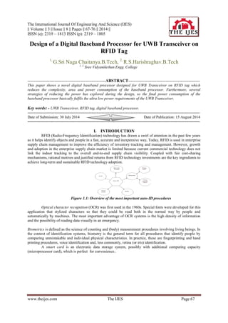
  • 1. The International Journal Of Engineering And Science (IJES) || Volume || 3 || Issue || 8 || Pages || 67-76 || 2014 || ISSN (e): 2319 – 1813 ISSN (p): 2319 – 1805 www.theijes.com The IJES Page 67 Design of a Digital Baseband Processor for UWB Transceiver on RFID Tag 1, G.Sri Naga Chaitanya.B.Tech, 2, R.S.Harishraghav.B.Tech 1, 2, Sree Vidyanikethan Engg. College -------------------------------------------------------------ABSTRACT-------------------------------------------------------- This paper shows a novel digital baseband processor designed for UWB Transceiver on RFID tag which reduces the complexity, area and power consumption of the baseband processor. Furthermore, several strategies of reducing the power has explored during the design, so the final power consumption of the baseband processor basically fulfils the ultra low power requirements of the UWB Transceiver. Key words: - UWB Transceiver, RFID tag, digital baseband processor. --------------------------------------------------------------------------------------------------------------------------------------- Date of Submission: 30 July 2014 Date of Publication: 15 August 2014 --------------------------------------------------------------------------------------------------------------------------------------- I. INTRODUCTION RFID (Radio-Frequency Identification) technology has drawn a swirl of attention in the past few years as it helps identify objects and people in a fast, accurate and inexpensive way, Today, RFID is used in enterprise supply chain management to improve the efficiency of inventory tracking and management. However, growth and adoption in the enterprise supply chain market is limited because current commercial technology does not link the indoor tracking to the overall end-to-end supply chain visibility. Coupled with fair cost-sharing mechanisms, rational motives and justified returns from RFID technology investments are the key ingredients to achieve long-term and sustainable RFID technology adoption. Figure 1.1: Overview of the most important auto-ID procedures Optical character recognition (OCR) was first used in the 1960s. Special fonts were developed for this application that stylized characters so that they could be read both in the normal way by people and automatically by machines. The most important advantage of OCR systems is the high density of information and the possibility of reading data visually in an emergency. Biometrics is defined as the science of counting and (body) measurement procedures involving living beings. In the context of identification systems, biometry is the general term for all procedures that identify people by comparing unmistakable and individual physical characteristics. In practice, these are fingerprinting and hand printing procedures, voice identification and, less commonly, retina (or iris) identification. A smart card is an electronic data storage system, possibly with additional computing capacity (microprocessor card), which is perfect for convenience..
  • 2. Design of a Digital Baseband Processor for UWB Transceiver on RFID Tag www.theijes.com The IJES Page 68 Table 1.1: Comparison of different auto-ID systems. 1.1 APPLICATIONS RFID is a versatile technology, capable of being used by businesses and the government. Mandates for supply chains, while raising the profile of RFID in business, have overshadowed how extensively and successfully RFID is used in other contexts. In the early part of the 21st century, RFID is growing. The list of RFID users is a long one’s • Supply Chains, Including Wholesale and Retail Inventory and Materials Management  Item-level Tagging of Consumer Goods on Retail Shelves  Toll Payment Systems  Smart Cards.  Contactless Payment Systems at the Retail Point of Sale (POS)  Logistics  Asset Tracking  Automobile Keyless Start Systems  Sports Pharmaceutical Anti-drug Counterfeiting II. RFID SYSTEM AND ITS COMPONENTS RFID systems are composed of three key components. • The RFID tag, or transponder, carries object identifying data. • The RFID tag reader, or transceiver, reads and writes tag data. • The back-end database stores records associated with tag contents. Figure 2.1: RFID system components A key classification of RFID tags is the source of power. Tags come in three general varieties: active, semi-passive and passive. Active tags contain an on-board power source, such as a battery, as well as the ability to initiate their own communications; possibly with other tags. Semi-passive tags have a battery, but may only respond to incoming transmissions. Passive tags have no internal power source and receive all power from the reader. Table 2.1 given below gives a brief idea of the different types of tags, its power source, transmitter and its maximum operating range. Figure 2.2 is the appearance or the display of the available passive, semi passive and active tags Table 2.1: Active, Semi-Passive and Passive tags RF circuit & analog circuit Baseband processor EEPROM READER
  • 3. Design of a Digital Baseband Processor for UWB Transceiver on RFID Tag www.theijes.com The IJES Page 69 Figure 2.2: Passive tag, Semi passive tag, Active tag 2.1 OPERATING PRINCIPLE OF RFID SYSTEM An Interrogator receives information from a Tag by transmitting an un-modulated RF carrier and listening for a backscattered reply. Tags communicate information by backscatter-modulating the amplitude and/or phase of the RF carrier. The encoding format, selected in response to Interrogator commands, is either FM0 or Miller modulated sub-carrier. The communications link between Interrogators and Tags is half-duplex, meaning that Tags shall not be required to demodulate Interrogator commands while backscattering. A Tag shall not respond using full-duplex communications to a mandatory or optional command. RFID tag chip consists of a power reception system, an RF analog module, an EEPROM and a baseband-processor, shown in figure.2.3. The figure 2.4 shown above is the block diagram of a UHF RFID tag system. The baseband-processor is one of the major and most important parts of the tag chip, since it not only implements the “slotted aloha” random anti-collision algorithm and authorization scheme, but also executes read/write operation of EEPROM. Figure 2.3: Architecture of the RFID tag Figure 2.4: Block diagram of an RFID tag system 2.2 HARDWARE MODELLING & IMPLEMENTATIONOFDIGITAL BASEBAND PROCESSOR Figure 2.5: Proposed block diagram of a baseband processor Figure 2.5 is the proposed block diagram of the Baseband processor. The baseband processor is the back-end part of the RFID system. The front-end part of the system comprises of a reader and the data communication between the processor and the reader takes place in half-duplex mode. The data flow between the sub modules is in parallel form synchronized with respect to clock. This can improve the efficiency of the Baseband processor significantly.
  • 4. Design of a Digital Baseband Processor for UWB Transceiver on RFID Tag www.theijes.com The IJES Page 70 III. INTRODUCTIONS TO VERILOG HDL 3.1 INTRODUCTION TO VERILOG LANGUAGE There is no attempt in this handout to describe the complete Verilog language. It describes only the portions of the language needed to allow students to explore the architectural aspects of computers. In fact, this handout covers only a small fraction of the language. For the complete description of the Verilog HDL, consult the references at the end of the handout. 3.2 A FIRST VERILOG PROGRAM module simple; // Simple Register Transfer Level (RTL) example to demo Verilog. // Register A is incremented by one. Then first four bits of B is // set to "not" of the last four bits of A. C is the "and" // reduction of the last two bits of A. //declare registers and flip-flops reg [0:7] A, B; reg C; // The two "initial"s and "always" will run concurrently initial begin: stop at // Will stop the execution after 20 simulation units. #20; $stop; end // These statements done at simulation time 0 (since no #k) initial begin: Init // Initialize register A. Other registers have values of "x" A = 0; // Display a header $display ("Time A B C"); // Prints the values anytime a value of A, B or C changes $monitor (“%0d %b %b %b", $time, A, B, C); end //main process will loop until simulation is over always begin: main process // #1 means do after one unit of simulation time #1 A = A + 1; #1 B[0:3] = ~A[4:7]; // ~ is bitwise "not" operator #1 C = &A[6:7]; // bitwise "and" reduction of last 2 bits of A end end module In module simple, we declared A and B as 8-bit registers and C a 1-bit register or flip-flop. Inside of the module, the one "always" and two "initial" constructs describe three threads of control, i.e., they run at the same time or concurrently. Within the initial construct, statements are executed sequentially much like in C or other traditional imperative programming languages. The always construct is the same as the initial construct except that it loops forever as long as the simulation runs. Below is the output of the VeriWell Simulator: (See Section 3 on how to use the VeriWell simulator.) Time A B C 0 00000000 xxxxxxxx x 1 00000001 xxxxxxxx x 2 00000001 1110xxxx x 3 00000001 1110xxxx 0 4 00000010 1110xxxx 0 5 00000010 1101xxxx 0 7 00000011 1101xxxx 0 8 00000011 1100xxxx 0 9 00000011 1100xxxx 1
  • 5. Design of a Digital Baseband Processor for UWB Transceiver on RFID Tag www.theijes.com The IJES Page 71 10 00000100 1100xxxx 1 11 00000100 1011xxxx 1 12 00000100 1011xxxx 0 13 00000101 1011xxxx 0 14 00000101 1010xxxx 0 16 00000110 1010xxxx 0 17 00000110 1001xxxx 0 19 00000111 1001xxxx 0 Stop at simulation time 20 3.3 LEXICAL CONVENTIONS The lexical conventions are close to the programming language C++. Comments are designated by // to the end of a line or by /* to */ across several lines. Keywords, e. g., module, are reserved and in all lower case letters. The language is case sensitive, meaning upper and lower case letters are different. Spaces are important in that they delimit tokens in the language. Numbers are specified in the traditional form of a series of digits with or without a sign but also in the following form: <size><base format><number> Where <size> contains decimal digits that specify the size of the constant in the number of bits. The <size> is optional. The <base format> is the single character ' followed by one of the following characters b, d, o and h, which stand for binary, decimal, octal and hex, respectively. The <number> part contains digits which are legal for the <base format>. Some examples: 549 // decimal number 'h 8FF // hex number 'o765 // octal number 4'b11 // 4-bit binary number 0011 3'b10x // 3-bit binary number with least // significant bit unknown 5'd3 // 5-bit decimal number -4'b11 // 4-bit two's complement of 0011 or 1101 The <number> part may not contain a sign. Any sign must go on the front. A string is a sequence of characters enclosed in double quotes. "this is a string" Operators are one, two or three characters and are used in expressions. An identifier is specified by a letter or underscore followed by zero or more letters, digits, dollar signs and underscores. Identifiers can be up to 1024 characters. 3.4 CONTROL CONSTRUCTS Verilog HDL has a rich collection of control statements which can used in the procedural sections of code, i. e., within an initial or always block. Most of them will be familiar to the programmer of traditional programming languages like C. The main difference is instead of C's { } brackets, Verilog HDL uses begin and end. In Verilog, the { } brackets are used for concatenation of bit strings. Since most users are familiar with C, the following subsections typically show only an example of each construct. 3.4.1 Selection - if and case Statements The if statement is easy to use. if (A == 4) begin B = 2; end else begin B = 4; End Unlike the case statement in C, the first <value> that matches the value of the <expression> is selected and the associated statement is executed then control is transferred to after the endcase, i. e., no break statements are needed as in C.
  • 6. Design of a Digital Baseband Processor for UWB Transceiver on RFID Tag www.theijes.com The IJES Page 72 case (<expression>) <value1>: <statement> <value2>: <statement> default: <statement> endcase The following example checks a 1-bit signal for its value. case (sig) 1'bz: $display("Signal is floating"); 1'bx: $display("Signal is unknown"); default: $display("Signal is %b", sig); endcase 3.4.2 Repetition - for, while and repeat Statements The for statement is very close to C's for statement except that the ++ and -- operators do not exist in Verilog. Therefore, we need to use i = i + 1. for(i = 0; i< 10; i = i + 1) begin $display("i= %0d", i); end The while statement acts in the normal fashion. i = 0; while(i< 10) begin $display("i= %0d", i); i = i + 1; end The repeat statement repeats the following block a fixed number of times, in this example, five times. repeat (5) begin $display("i= %0d", i); i = i + 1; end 3.5 OTHER STATEMENTS 3.5.1 Parameter Statement The parameter statement allows the designer to give a constant a name. Typical uses are to specify width of registers and delays. For example, the following allows the designer to parameterized the declarations of a model parameterbyte_size = 8; reg [byte_size - 1:0] A, B; 3.5.2 Continuous Assignment Continuous assignments drive wire variables and are evaluated and updated whenever an input operand changes value. The following ands the values on the wires in1 and in2 and drives the wire out. The keyword assign is used to distinguish the continuous assignment from the procedural assignment. See Section 2.1 for more discussion on continuous assignment. Assignout = ~(in1 & in2); 3.5.3 Blocking and Non-blocking Procedural Assignments The Verilog language has two forms of the procedural assignment statement: blocking and non- blocking. The two are distinguished by the = and <= assignment operators. The blocking assignment statement (= operator) acts much like in traditional programming languages. The whole statement is done before control passes on to the next statement. The non-blocking (<= operator) evaluates all the right-hand sides for the current time unit and assigns the left-hand sides at the end of the time unit. For example, the following Verilog program // testing blocking and non-blocking assignment module blocking;
  • 7. Design of a Digital Baseband Processor for UWB Transceiver on RFID Tag www.theijes.com The IJES Page 73 reg [0:7] A, B; initial begin: init1 A = 3; #1 A = A + 1; // blocking procedural assignment B = A + 1; $display("Blocking:A= %b B= %b", A, B ); A = 3; #1 A <= A + 1; // non-blocking procedural assignment B <= A + 1; #1 $display("Non-blocking: A= %b B= %b", A, B ); end end module produces the following output: Blocking: A= 00000100 B= 00000101 Non-blocking: A= 00000100 B= 00000100 The effect is for all the non-blocking assignments to use the old values of the variables at the beginning of the current time unit and to assign the registers new values at the end of the current time unit. This reflects how register transfers occur in some hardware systems. 3.6 TASKS AND FUNCTION: Tasks are like procedures in other programming languages, e. g., tasks may have zero or more arguments and do not return a value. Functions act like function subprograms in other languages. Except: 1. A Verilog function must execute during one simulation time unit. That is, no time controlling statements, i. e., no delay control (#), no event control (@) or wait statements, allowed. A task may contain time controlled statements. 2. A Verilog function can not invoke (call, enable) a task; whereas a task may call other tasks and functions. The definition of a task is the following: task<task name>; // Notice: no parameter list or ()s <argument ports> <declarations> <statements> End task An invocation of a task is of the following form: <name of task> (<port list>); where<port list> is a list of expressions which correspond by position to the <argument ports> of the definition. Port arguments in the definition may be input, inout or output. Since the <argument ports> in the task definition look like declarations, the programmer must be careful in adding declares at the beginning of a task. // Testing tasks and functions // Dan Hyde, Aug 28, 1995 module tasks; task add; // task definition input a, b; // two input argument ports output c; // one output argument port reg R; // register declaration begin R = 1; if (a == b) c = 1 & R; else c = 0; end end task
  • 8. Design of a Digital Baseband Processor for UWB Transceiver on RFID Tag www.theijes.com The IJES Page 74 initial begin: init1 reg p; add(1, 0, p); // invocation of task with 3 arguments $display("p= %b", p); end end module input and inout parameters are passed by value to the task and output and inoutparameters are passed back to invocation by value on return. Call by reference is not available. 3.7 TIMING CONTROL The Verilog language provides two types of explicit timing control over when simulation time procedural statements are to occur. The first type is a delay control in which an expression specifies the time duration between initially encountering the statement and when the statement actually executes. The second type of timing control is the event expression, which allows statement execution. The third subsection describes the wait statement which waits for a specific variable to change. Verilog is a discrete event time simulator, i. e., events are scheduled for discrete times and placed on an ordered-by-time wait queue. If there is no timing control, simulation time does not advance. Simulated time can only progress by one of the following: 1. gate or wire delay, if specified. 2. a delay control, introduced by the # symbol. 3. an event control, introduced by the @ symbol. 4. thewait statement. The order of execution of events in the same clock time may not be predictable. 3.7.1 DELAY CONTROL A delay control expression specifies the time duration between initially encountering the statement and when the statement actually executes. For example: #10 A = A + 1; specifies to delay 10 time units before executing the procedural assignment statement. The # may be followed by an expression with variables. 3.7.2 EVENTS The execution of a procedural statement can be triggered with a value change on a wire or register, or the occurrence of a named event. Some examples: @r begin // controlled by any value change in A = B&C; // the register r end @(posedge clock2) A = B&C; // controlled by positive edge of clock2 @(negedge clock3) A = B&C; // controlled by negative edge of clock3 forever @(negedge clock) // controlled by negative edge begin A = B&C; end In the forms using posedge and negedge, they must be followed by a 1-bit expression, typically clock. A negedge is detected on the transition from 1 to 0 (or unknown). A posedge is detected on the transition from 0 to 1 (or unknown). Verilog also provides features to name an event and then to trigger the occurrence of that event. We must first declare the event: event event6; To trigger the event, we use the ->symbol : -> event6; To control a block of code, we use the @ symbol as shown: @(event6) begin <some procedural code> end We assume that the event occurs in one thread of control, i. e., concurrently, and the controlled code is in another thread. Several events may to or-ed inside the parentheses.
  • 9. Design of a Digital Baseband Processor for UWB Transceiver on RFID Tag www.theijes.com The IJES Page 75 3.7.3 WAIT STATEMENT The wait statement allows a procedural statement or a block to be delayed until a condition wait (A == 3) begin A = B&C; end The difference between the behavior of a wait statement and an event is that the wait statement is level sensitive whereas @(posedge clock); is triggered by a signal transition or is edge sensitive. 3.7.4 FORK AND JOIN STATEMENTS By using the fork and join construct, Verilog allows more than one thread of control inside an initial or always construct. For example, to have three threads of control, you fork the thread into three and merge the three into one with a join as shown: fork: three //split thread into three; one for each begin-end begin // code for thread 1 end begin // code for thread 2 end begin // code for thread 3 end join // merge the three threads to one Each statement between the fork and join, in this case, the three begin-end blocks, is executed concurrently. After all the threads complete, the next statement after the join is executed. You must be careful that there is no interference between the different threads. For example, you can't change a register in two different threads during the same clock period. IV. 4. RESULT ANALYSIS The Verilog HDL code is written for both reference design • According to [1] given in figure 4.3, the controller in the architecture of the Baseband processor controls the data flow to the other sub modules. It sends control signals to control the status of all the sub modules. • But the modified design given in fig 4.7 incorporates a controller which controls not only the data flow to the sub modules but also controls the clock of each sub module. This reduces the power significantly. Figure4.1: Simulation result of the reference design obtained in xilinx tool Figure4.2: Simulation result of the modified design obtained in xilinx tool
  • 10. Design of a Digital Baseband Processor for UWB Transceiver on RFID Tag www.theijes.com The IJES Page 76 Figure 4.1 and figure 4.2 shown above are the simulation result of the reference design and the simulation result of the modified design obtained in Xilinx tool respectively. The design was simulated and synthesized using Xilinx tool. The selected device was Spartan 3E. The Clock of100 MHz was provided. Reset signal is active high. The input bits are 88 bits serial and the output obtained is 88 bits serial which is amplitude modulated. The internal operation is carried on parallel. One of the given test cases is 11001111000000010000000100000001000000010000000100000001000000010000000 1111111111111111 Expected output is: 011001111000000010000000100000001000000010000000100000001000000010000000101111100010110 The power analysis for both the reference design and modified design were carried out. The dynamic power obtained for both the designs are given in the Table 4.3 below. Table 5.1: Dynamic power obtained from xilinx tool CONCLUSION In this paper, a novel digital baseband processor designed for UWB Transceiver on RFID tag is presented. Due to the security feature and other advantages of UWB, no complicated coding and cryptography is needed. This also reduces the complexity, area and power consumption of the baseband processor. Furthermore, several strategies of reducing the power has explored during the design, so the final power consumption of the baseband processor basically fulfills the ultra low power requirements of the UWB Transceiver. Future works include integrating the baseband processor into the UWB Transceiver to test the whole system and researching for more strategies to reduce the power consumption of the baseband processor if possible. REFERENCES [1]. YuechaoNiu, Majid BaghaeiNejad, HannuTenhunen and Li-Rong Zheng, “Design of a Digital Baseband Processor for UWB Tranceiver on RFID Tag”, IEEE Conference on Advanced Information Networking and Applications Workshop proceedings, vol. 2, pp. 358-361, May 2007 [2]. Adam S.W. Man, Edward S. Zhang, H.T. Chan, Vincent K.N. Lau, C.Y. Tsui and Howard C. Luong,“Design and Implementation of a Low-power Baseband-system for RFID Tag”IEEE International Solid-State Circuits Conference, pp. 1585- 1588, May 2007 [3]. Usami M, Tanabe H, Sato A, Sakama I, Maki Y, Iwamatsu T, Ipposhi T and Inoue Y, “A 0.05×0.05mm2 RFID Chip with Easily Scaled-Down ID-Memory”, IEEE International Solid-State Circuits Conference, pp. 482-483, February 2007 [4]. He Yan, Hu Jianyun,LiQiang and Min Hao, “Design of Low-power Baseband processor for RFID Tag”, Proceedings of the IEEE International Symposium on Applications and the Internet Workshops, vol. 1, pp. 1-4, January 2006 [5]. He Yan, Hu Jianyun,LiQiang and Min Hao, “Design of Low-power Baseband processor for UHF RFID Tag”, 6th International Conference On ASIC, ASICON 2005, vol. 1, pp. 143-146, October 2005